1
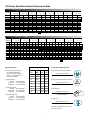
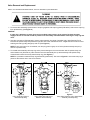
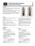
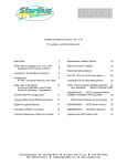
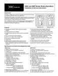
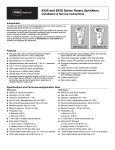
750 Series Rotary Sprinkler
INSTALLATION & SERVICE INSTRUCTIONS
Introduction
The 754 Full-Circle Rotary Sprinkler is designed for irrigation of large turf areas such as golf courses, parks, recreational
fields and school grounds.
Manufactured from durable, high-strength engineering plastic and stainless-steel components, the 754 sprinkler incorporates
many innovative and time-proven features for lasting, maintenance-free operation. Some of these features are listed below:
Specifications
■
■
■
■
■
■
■
■
■
■
■
■
Features
Radius: 56 ft. – 100 ft. (17.1 m – 30.4 m)
Flow Rate:
■ 13.0 – 60.1 GPM
■ 49.2 – 227.5 l/mn
3
■ 3.0 – 13.7 m /hr
Arc: Full Circle
Maximum Pressure:
2
■ Electric VIH - 150 PSI (10.5 kg/cm ) (1034.5 kPa)
2
■ NO Hyd. VIH - 100 PSI (7.0 kg/cm ) (689.7 kPa)
2
■ NC Hyd. VIH - 150 PSI (10.5 kg/cm ) (1034.5 kPa)
2
■ Check-O-Matic - 100 PSI (7.0 kg/cm ) (689.7 kPa)
Body Height: 11 in. (27.9 cm)
Pop-Up Height: 2.75 in. (6.9 cm)
Pop-Up to Nozzle: 2 in. (5.1 cm)
1.5 in. NPT, BSP or ACME Female Thread Inlet
Solenoid:
■ 24 VAC, 50/60 Hz
■ Inrush Current:
50 Hz, 0.47 Amps (11.3 VA)
60 Hz, 0.40 Amps (9.6 VA)
■ Holding Current: 50 Hz, 0.32 Amps (7.7 VA)
60 Hz, 0.30 Amps (7.2 VA)
Manual Control: On-Off-Auto
Check-O-Matic model checks up to 37 ft. (11.3 m) of
elevation
Color-Coded Nozzles: See chart on page 2.
750 Electric
■
■
■
■
■
■
■
■
■
■
■
■
■
Full 3" pop-up to clear taller grasses
Nozzles color-coded by radius and gallonage
Caps serve as yardage markers or effluent water indicators
Variable stator
Four standard pressure-regulation settings available to
ensure ocnsistently accurate nozzle performance
regardless of elevation:
❚ 50 PSI, 65 PSI, 80 PSI and 100 PSI (electric)
Four body styles/activation types to fit every application:
Electric VIH, Normally Open Hydraulic VIH, and
Check-O-Matic
Manual control at the sprinkler, On-Off-Auto (electric)
Bowl-vented discharge (atmospheric) minimizes the
differential pressure required for regulation and ensures
positive valve closure (electric)
Time-proven planetary gear-drive design
All internal components serviceable from the top of the
sprinkler
Large selection of color-coded nozzles available
Durable engineering plastic and stainless-steel construction
Effluent indicators available
❚ Marker (Part No. 89-4719)
❚ Yardage marker (Part No. 89-4736)
750 Normally Open Valve-In-Head
750 Check-O-Matic
750 Series Sprinkler Nozzle Performance Data
NOZZLE PERFORMANCE — U.S.
BASE
PRESSURE
NOZZLE SET
NOZZLE SET
NOZZLE SET
NOZZLE SET
NOZZLE SET
NOZZLE SET
NOZZLE SET
NOZZLE SET
52
53
54
55
56
57
58
59
ORANGE
BROWN
BLUE
GREEN
RED
GRAY
BEIGE
BLACK
PSI
Rad
GPM
Rad
GPM
Rad
GPM
Rad
GPM
Rad
GPM
Rad
GPM
Rad
GPM
Rad
GPM
50
55
60
65
70
75
80
85
90
95
100
56
57
57
58
59
59
60
62
63
65
66
13.0
13.5
14.0
14.5
15.0
15.6
16.1
17.4
18.7
19.9
21.2
61
62
62
63
65
66
68
69
70
71
72
16.8
17.6
18.3
19.1
19.8
20.4
21.1
22.2
23.4
24.5
25.6
65
66
68
69
72
72
74
75
76
76
77
20.0
20.9
21.8
22.8
23.6
24.5
25.3
26.8
28.4
29.9
31.4
67
68
69
70
73
73
75
76
78
79
80
25.3
26.5
27.7
28.9
29.9
30.9
32.0
33.4
34.8
36.2
37.6
68
69
71
72
75
75
77
78
80
81
82
30.0
31.5
33.0
34.6
36.0
37.4
38.9
39.9
41.0
42.0
43.0
70
73
77
80
81
83
84
86
87
89
90
32.5
33.6
34.7
35.8
37.3
38.8
40.3
41.7
43.1
44.4
46.8
73
76
78
81
83
84
86
88
89
91
92
37.4
38.9
40.4
41.9
43.7
45.5
47.4
50.2
53.0
55.7
58.6
78
81
84
87
89
90
92
94
96
98
100
40.1
41.6
43.1
44.5
46.4
48.3
50.2
52.7
55.2
57.6
60.1
Rad = feet
GPM = gallons per minute
■ = Pressure regulation
■ = Nozzles not recommended at this pressure
NOZZLE PERFORMANCE — METRIC
kg/cm2 kPa
3.5
3.9
4.2
4.6
4.9
5.3
5.6
6.0
6.3
6.7
7.0
344.7
379.2
413.7
448.2
482.6
517.1
551.6
586.1
620.5
655.0
689.5
NOZZLE SET
NOZZLE SET
NOZZLE SET
NOZZLE SET
NOZZLE SET
NOZZLE SET
NOZZLE SET
53
54
55
56
57
58
52 ORANGE
❚
❚
GREEN
RED
GRAY
NOZZLE SET
59
BEIGE
BLACK
l/mn m3/hr Rad
l/mn m3/hr Rad
l/mn m3/hr Rad
l/mn m3/hr Rad
l/mn m3/hr Rad
l/mn m3/hr
Rad
l/mn m3/hr Rad
l/mn m3/hr
17.1
17.4
17.4
17.7
18.0
18.0
18.3
18.9
19.2
19.8
20.1
49.2
51.1
53.0
54.9
56.8
59.0
60.9
65.9
70.8
75.3
80.2
63.6
66.6
69.3
72.3
74.9
77.2
79.9
84.0
88.6
92.7
96.9
75.7
79.1
82.5
86.3
89.3
92.7
95.8
101.4
107.5
113.2
118.8
95.8
100.3
104.8
109.4
113.2
117.0
121.1
126.4
131.7
137.0
142.3
113.6
119.2
124.9
131.0
136.3
141.6
147.2
151.0
155.2
159.0
162.8
123.0
127.2
131.3
135.5
141.2
146.9
152.5
157.8
163.1
168.1
177.1
22.3
23.2
23.8
24.7
25.3
25.6
26.2
26.8
27.1
27.8
28.1
141.6
147.2
152.9
158.6
165.4
172.2
179.4
190.0
200.6
210.8
221.8
151.8
157.5
163.1
168.4
175.6
182.8
190.0
199.5
208.9
218.0
227.5
3.0
3.1
3.2
3.3
3.4
3.5
3.7
4.0
4.2
4.5
4.8
Rad = meters
18.6
18.9
18.9
19.2
19.8
20.1
20.7
21.0
21.4
21.7
22.0
3.8
4.0
4.2
4.3
4.5
4.6
4.8
5.0
5.3
5.6
5.8
19.8
20.1
20.7
21.0
22.0
22.0
22.6
22.9
23.2
23.2
23.5
4.5
4.7
5.0
5.2
5.4
5.6
5.7
6.1
6.5
6.8
7.1
20.4
20.7
21.0
21.4
22.3
22.3
22.9
23.2
23.8
24.1
24.4
5.7
6.0
6.3
6.6
6.8
7.0
7.3
7.6
7.9
8.2
8.5
The Toro Company does not
recommend designing for
zero (0) mph wind conditions.
Design in consideration of the
worst wind conditions.
Square Spacing
No wind - 55% of diameter
4 mph wind - 50% of diameter
8 mph wind - 45% of diameter
Triangular Spacing
No wind - 60% of diameter
4 mph wind - 55% of diameter
8 mph wind - 50% of diameter
20.7
21.0
21.7
22.0
22.9
22.9
23.5
23.8
24.4
24.7
25.0
Nozzle Color-Coding Guide
Long
Main
6.8
7.2
7.5
7.9
8.2
8.5
8.8
9.1
9.3
9.5
9.8
21.4
22.3
23.5
24.4
24.7
25.3
25.6
26.2
26.5
27.1
27.5
■ = Pressure regulation
l/mn = liters per minute m3/hr - cubic meters per hour
Sprinkler Spacing
❚
BLUE
Rad
kPa = kilo Pascals
❚
BROWN
Nozzle
Set
Short
Main
Long
Inner
52
Orange
Red
53
Brown
Red
54
Blue
Red
55
Green
Black
56
Red
Black
57
Gray
Black
58
Beige
Green
59
Black
Green
Single-Row Spacing
No wind - 50% of diameter
4 mph wind - 50% of diameter
8 mph wind - 45% of diameter
7.4
7.6
7.9
8.1
8.5
8.8
9.2
9.5
9.8
10.1
10.6
8.5
8.8
9.2
9.5
9.9
10.3
10.8
11.4
12.0
12.7
13.3
❚
Square-spaced sprinklers in pattern:
GPM of full circle x 96.3
(Spacing)2
❚
Triangular-spaced sprinklers in pattern:
GPM of full circle x 96.3
(Spacing)2 (0.866)
❚
9.1
9.4
9.8
10.1
10.5
11.0
11.4
12.0
12.5
13.1
13.7
■ = Nozzles not recommended at this pressure
Precipitation Rate Formulas
Area and flow:
Total GPM of zone x 96.3
Total irrigated
square feet of zone
❚
Single row:
GPM of full circle x 96.3
(Spacing) (Scallop)
For additional information, refer to Toro
Form No. 490-1737.
2
23.8
24.7
25.6
26.5
27.1
27.5
28.1
28.7
29.3
29.9
30.5
Scallop
BASE
PRESSURE
Spacing
Installation Procedure _________________________________________________
CAUTION
Golf sprinklers are intended for installation at grade with full
support of the body and piping system from the surrounding
earth. Failure to provide full support may result in premature
failure of the body and/or connecting fittings.
Figure 1: Triple Swing Joints
RIES ER
7 5 0 SFES P R I N K L
TUR
OFF
AUTO
ON
(NPT & BSP
models only)
To assure maximum performance from your 754 Series Rotary Sprinklers,
read these instructions completely prior to installation or service.
Swing Joints
1. Construct or provide triple swing joints for each sprinkler as shown
in Figure 1. Use PVC or ABS pipe nipple for sprinkler connection.
Note: On sites where the possibility of heavy equipment rolling over
a sprinkler exists, the swing joint will flex preventing damage to the
lateral or main lines. On a new installation in raw ground where the
sprinklers are to be initially installed above the finished grade and
lowered when new turf is established, the swing joint allows
sprinkler repositioning without changing risers. This is a common
and practical procedure which eliminates the problem of dirt being
accidentally introduced into the lateral lines when a riser is changed.
RIES ER
7 5 0 SFES P R I N K L
TUR
OFF
AUTO
ON
(ACME
models only)
2. Flush lines thoroughly prior to installing sprinkler.
3. NPT and BSP Threaded Models
• Apply teflon tape on riser threads. Install sprinkler onto riser
and tighten.
ACME Threaded Models
• Install ACME threaded bodies onto Acme threaded swing joint by
threading clockwise until hand tight
Note: ACME threaded swing joints have an o-ring that seals to
the sprinkler body. Teflon tape is not required..
CAUTION
Use only Teflon™ tape on riser threads. Use of pipe dope or other types of sealing compounds can cause
deterioration of sprinkler body threads.
Table 1:
Connecting Electric Control Wires
1. Route control wires to sprinkler location(s). Provide enough
extra wire at sprinkler to allow for movement of sprinkler without
straining wire connections. One common wire and station wire is
required for each sprinkler. See Wire Sizing Chart, Table 1 for
proper application.
2. Attach control wires to solenoid leads using an approved
waterproof splicing method.
CAUTION
All wires must be waterproofed to prevent short circuit to
ground and subsequent controller damage.
Wire Sizing Chart
Maximum allowable length in feet from controller to electric VIH
sprinklers.
OUTPUT
VOLTAGEAT
VOLTAGE
AT
CONTROLLER
CONTROLLER
TRANSFORMER
23
23
23
23
23
23
23
24
24
24
24
24
24
24
VAC
VAC
VAC
VAC
VAC
VAC
VAC
VAC
VAC
VAC
VAC
VAC
VAC
VAC
WIRE
SIZE
CONTROL
14
14
14
12
12
12
10
14
14
14
12
12
12
10
COMMON
14
12
10
12
10
8
10
14
12
10
12
10
8
10
NUMBER
OF VALVES
1
2348
2890
3378
3759
4591
5411
5945
2765
3393
3962
4394
5397
6364
6986
2
1012
1239
1448
1604
1973
2328
2555
1309
1608
1877
2082
2557
3018
3311
3
549
673
786
873
1071
1263
1387
846
1039
1213
1346
1652
1949
2140
NOTE: Minimum solenoid voltage required for reliable electric
VIH operation is 20 VAC.
3
Chart based on the following
Transformer - 115/230 VAC - 24 VAC, 45 VA
Coil Assy.
- 24 VAC, 60 Hz
Holding
- .30 Amps
In Rush
- .40 Amps
4
353
433
505
561
688
812
892
549
673
783
872
1071
1263
1387
Connecting Hydraulic Control Tubing
Table 2:
1. Route control tubing from controller to sprinkler
location(s).
Type of System*
Note: Leave an 18 inch (45.7 cm) service loop
of tubing at each sprinkler to facilitate
movement of sprinkler and service operations.
Refer to Table 2 for tubing run length information.
2. Flush tubing thoroughly to remove all air and
debris.
3. Remove tube retainer and poly cap from tubing
adapter at base of sprinkler.
4. Slide tube retainer over control tubing and
attach tubing to adapter. Slide tube retainer
over adapter area to secure tubing.
Control Systems
Maximum Distance
From Controller
Elevation Restrictions
Pin-type£ (00) Hydraulic*
with 3⁄16" Control Tubing
100'
Pin-type£ (00) Hydraulic*
with 1⁄4" Control Tubing
200'
Normally Open (01)
with 3⁄16" Control Tubing
500'
Valve elevation should not exceed
25' ABOVE controller elevation or
70' BELOW controller elevation.
Normally Closed (08)
with 3⁄16" Control Tubing
500'
Valve elevation should not exceed
0' ABOVE controller elevation or
70' BELOW controller elevation.
Normally Open (01)
with 1⁄4" Control Tubing
1000'
Valve elevation should not exceed
25' ABOVE controller elevation or
70' BELOW controller elevation.
Normally Closed (08)
with 1⁄4" Control Tubing
1000'
Valve elevation should not exceed
0' ABOVE controller elevation or
70' BELOW controller elevation.
* - All hydraulic connections on Toro valves are 1⁄4" insert type.
- Control line pressure must be equal to or 10% greater than mainline pressure.
- Control line pressure range is 40 to 150 PSI
£ NOTE: Maximum of one (1) valve pr station on pin-type systems.
System Start-Up
The following is a recommended procedure that will protect system components during system start-up. The procedure is based on a
velocity fill rate of less than 2' (.61 m) per second. See Table 3 below.
1. Use jockey pump only to fill system at velocity fill rate of less than 2' (0.6 m) per second.
2. Use quick coupler keys at all tees and greens with quick coupler valves to bleed air from system lines during filling process. Do
not compress air and then relieve, bleed air while filling system.
3. After water has filled all lines and all air is removed, remove quick coupler keys.
CAUTION
Failure to comply with recommended fill rate will increase line pressure resulting in a water hammer effect that could
damage sprinklers.
Table 3:
Pipe Size
in.
1/2
3/4
1
1-1/4
1-1/2
2
2-1/2
cm
1.3
1.9
2.5
3.2
3.8
5.0
6.4
Flow
GPM
2
3
5
10
10
20
30
LPM
7.6
11.4
18.9
37.9
37.9
75.7
113.6
Recommended System Fill Rate
Velocity
ft/sec
1.60
1.92
1.50
1.86
1.41
1.80
1.84
m/sec
0.49
0.59
0.46
0.57
0.43
0.55
0.56
Pipe Size
in.
3
4
6
8
10
12
4
cm
7.6
10.2
15.2
20.2
25.4
30.5
Flow
GPM
45
75
150
250
450
500
LPM
170.3
283.9
567.8
946.3
1703.3
1892.5
Velocity
ft/sec
1.86
1.87
1.73
1.70
1.97
1.55
m/sec
0.57
0.57
0.53
0.52
0.60
0.47
Pilot Valve Operation (Models 7XX-X6-XXX Only)
The main function of the pilot valve is to control the operation of the main valve located in the base of the sprinkler body. The main valve
is operated by the release of water metered through the pilot valve when it is activated either manually at the sprinkler or by the
irrigation system controller.
Another important function of the pilot valve is to regulate the water pressure to the sprinkler nozzle. Pressure regulation compensates
for large variations within the system and maintains a constant pressure for optimum sprinkler operation. The pilot valve is factory set to
regulate one of four pressure levels 50 psi (3.5 kg/cm2), 65 psi (4.6 kg/cm2), 80 psi (6.0 kg/cm2) or 100 PSI (7.0 kg/cm2).
The sprinkler operation mode is set using a Toro Selector Tool (P/N 995-15) inserted through the body flange onto the pilot valve
D-shaped selector cam. The "AUTO" mode permits automatic operation from the system controller. The "ON" mode opens the main
valve for manual operation and "OFF" mode prevents the main valve from opening.
System Troubleshooting — Pilot Valve
Possible equipment failures with causes and corrective action are listed below.
PROBLEM
POSSIBLE CAUSE – CORRECTIVE ACTION
1.
SPRINKLER WILL
NOT TURN ON
(a) No 24 VAC to coil assembly. (Electric Models)
– Measure voltage with a Digital Volt Meter (DVM). Check wiring and controller program.
– Refer to Controller Operating Instructions.
(b) Selector cam in "OFF" position.
– Set to "AUTO" position.
(c) Debris in pilot valve assembly.
– Disassemble and remove all debris. (See Servicing Pilot Valve page 10.)
2.
SPRINKLER WILL
NOT SHUT OFF
(a) Constant 24 VAC from controller. (Electric Models)
– Check for voltage using a DVM. If voltage is present, disconnect wire.
If sprinkler closes, service controller. Refer to Controller Service Manual.
(b) Selector cam in manual "ON" position.
– Set to "AUTO" or "OFF" position.
(c) Debris in pilot valve assembly.
– Disassemble and remove all debris. (See Servicing Pilot Valve page 10.)
5
System Troubleshooting — Sprinklers
PROBLEM
1.
SPRINKLER WON'T ROTATE
POSSIBLE CAUSE – CORRECTIVE ACTION
(a)
(b)
(c)
2.
HEAD STICKS UP
(a)
(b)
(c)
3.
POOR DISTRIBUTION PATTERN
(a)
(b)
(c)
4.
VALVE WON'T CLOSE
(Electric 7XX-X6-XXX)
(a)
(b)
(c)
(d)
(e)
(f)
(g)
(h)
VALVE WON'T CLOSE
(Hyd. Normally Open
7XX-X1-XX)
(a)
(b)
(c)
(d)
(e)
Debris wedged between stator and turbine.
– Remove obstruction.
Drive assembly defective.
– Replace drive assembly.
Nozzle base assembly defective.
– Replace nozzle base assembly.
Dirt in riser assembly.
– Flush out. (See Flushing Procedure on page 10.)
Damaged or missing return spring.
– Replace.
Damaged riser.
– Replace.
Nozzle plugged with debris.
– Clean or replace nozzle.
Nozzle orifice damaged.
– Replace nozzle.
Low operating pressure.
– Determine why system overloaded and correct.
Continuous 24 VAC to sprinkler.
– Check controller for voltage source.
Leak in pilot valve assembly.
– Replace pilot valve assembly.
Plugged supply screen on piston.
– Clean or replace screen.
Manual control selector on pilot valve assembly turned to "ON" position.
– Turn to "AUTO" position.
Solenoid plunger movement restricted.
– Inspect and clean or replace.
Valve cylinder misaligned with sprinkler body communication tube.
– Remove valve assembly and install correctly.
Foreign object keeping valve from seating.
– Remove, clean and check valve for damage. Replace if necessary.
Damaged piston seal or piston assembly.
– Replace valve assembly.
Leak in control tubing.
– Isolate and repair.
Pilot valve leak in controller.
– Confirm by observing constant dripping from discharge line of controller.
Refer to Controller Service Manual.
Valve cylinder misaligned with sprinkler body communication tube.
– Remove valve assembly and install correctly.
Foreign object keeping valve from seating.
– Remove, clean and check valve for damage. Replace if necessary.
Damaged piston seal or piston assembly.
– Replace valve assembly.
6
System Troubleshooting — Sprinklers
PROBLEM
5.
VALVE WON'T OPEN
(Electric 7XX-X6-XXX)
POSSIBLE CAUSE – CORRECTIVE ACTION
(a)
(b)
(c)
(d)
(e)
(f)
(g)
6.
Control (field) wires severed.
– Isolate and repair.
No power to controller.
– Establish controller power.
No power from controller to solenoid.
– Check for blown fuse and replace.
Manual control selector on pilot valve assembly turned to "OFF" position.
– Turn to "AUTO" position.
Pilot valve solenoid inoperative.
– Remove and replace.
Solenoid plunger movement restricted.
– Inspect, clean and/or replace.
No supply from main valve.
– Debris in control tube, main valve assembly and/or communication
passages in body. Flush thoroughly.
VALVE WON'T OPEN
(Hyd. Normally Open
7XX-X1-XX)
(a)
Plugged controller discharge line or discharge port in pilot valve.
– Verify by checking for discharge at discharge line when station is
activated. If no discharge, refer to Controller Service Manual.
SPRINKLER WEEPING
(Slow leak in valve)
(a)
Damaged or blocked valve seat.
– Remove blockage and, if necessary, replace valve assembly.
Damaged piston seal or piston assembly.
– Replace valve assembly.
Low pressure on supply line on hydraulic NO sprinklers.
– Check for low pressure reason and correct.
(b)
(c)
7.
(continued)
SEVERAL VALVES ON DIFFERENT
STATIONS FAIL TO CLOSE
(Hyd. Normally Open
7XX-X1-XX)
(a)
(b)
(c)
(d)
Control tubing leak which lowers supply pressure to other stations.
– Turn controller from station to station until a station is reached where
only valves on that station stay open. The leak would be in the tubing
on that station. Isolate and repair.
Leak in supply line to controller.
– Verify by checking pressure in all control lines.
Leak in controller pilot valve.
– Verify by constant discharge on controller. Refer to Controller Service Manual.
Plugged supply line filter.
– Replace filter if more than 3 PSI (0.21 kg/cm2) differential exists.
7
Servicing Procedures
Introduction
The 754 sprinkler is designed to provide the user trouble-free operation for many years without scheduled maintenance.
Should it become necessary to disassemble the sprinkler to correct a malfunction or replace a component, all internal parts
of the sprinkler are accessible from the top. Refer to the Troubleshooting Procedure in this manual in the event of a
malfunction. Some special tools are required for disassembly and/or maintenance of the sprinkler and are available from
your Toro dealer.
Servicing Sprinkler Mechanism
Refer to Toro Illustrated Parts Breakout Book, Form No. 368-0044 for parts identification.
1. Lift Cap using knife blade edge or small screwdriver tip inserted between edge of Cap and Body flange.
2. Grasping edges of Cap, pull sprinkler mechanism up until fully extended.
3. While firmly holding Riser Assembly, remove Cap/Nozzle assembly by turning it counterclockwise. Allow Riser
Assembly to slowly retract into body.
4. Using two small screwdrivers inserted between Nozzle and Cap, separate Cap from Nozzle Assembly (retained by
press fit).
5. To change Nozzles, carefully insert knife blade edge between nozzle flange and base.
Pry nozzle loose and remove. Align new nozzle as shown in illustration at right. Carefully
press new nozzles into Nozzle Base until flange is fully seated. Avoid contact with
nozzle orifice as sprinkler coverage can be greatly impaired if orifice is damaged or
altered in any way.
6. Using Multi-Purpose Tool (P/N 995-83) remove Snap Ring from groove in body.
7. Thread Drive Assembly Extraction Tool (995-78) onto drive assembly output shaft and
pull sprinkler assembly out of body.
FLAT SPOT DOWN
8. Carefully remove O-ring from top of riser housing.
9. Using Multi-Purpose Tool (P/N 995-83) remove screen by turning it counterclockwise
while holding base of riser assembly.
10. Remove Variable Stator.
11. Remove Drive Assembly by pushing against end of threaded output shaft.
12. Inspect Stator Housing for nicks and burrs. This part can be difficult to remove if sprinkler has been in operation for
some time and should be left in place if it appears undamaged. If replacement is necessary, grasp housing with pliers
and pull from riser housing.
13. Thoroughly clean and inspect all parts. Replace damaged parts as necessary and reassemble in reverse order.
8
Valve Removal and Replacement
Refer to Toro Illustrated Parts Breakout Book, Form No. 368-0044 for parts identification.
1. To remove valve assembly, squeeze ears of snap ring together with snap ring pliers (P/N 995-07) and remove snap ring
from sprinkler body. (See Figure 2.)
CAUTION
If snap ring is difficult to remove, there may be residual water pressure in the system. Recheck the water
supply to ensure it is turned off and all pressure has been totally eliminated before removing the snap ring and
valve.
2. Use valve removal tool (P/N 995-09) to remove valve assembly from base of sprinkler body. Valve Removal Tool is
inserted into sprinkler body and pushed through valve ribs to the underside of valve. A slight twist will lock tool to valve
enabling removal by pulling straight up and out. (See Figure 3.)
NOTE: If valve removal tool is not available, use snap ring pliers to grasp rib of valve cylinder assembly and pull up
and out of sprinkler body.
3. To reinstall valve assembly with snap ring and to prevent damage to the communication tube in sprinkler body, use
valve insertion tool (P/N 995-10). Valve insertion tool will automatically line up valve assembly with sprinkler body
communication tube and correctly seat the snap ring. (See Figure 4.)
NOTE: It is possible to install the snap ring backwards (upside down). See inset in Figure 4 to insure that snap ring is
placed on the insertion tool in the correct manner.
Figure 2
Using Snap Ring Pliers to
Remove Snap Ring
Figure 3
Using Valve Removal Tool to
Remove Valve Assembly
9
Figure 4
Using Valve Insertion Tool to Install Valve
Assembly with Snap Ring
Flushing Sprinkler Heads
1. With sprinkler operating, carefully step down on center of cap several times. Water will flow around riser and flush out
debris.
2. Cycle sprinkler on and off several times to check for proper retraction. Cap should be even with top of body flange
when fully retracted. If riser sticks in up position, check for debris lodged between riser and body. Flush out all debris.
Remove sprinkler mechanism if necessary.
Servicing Pilot Valve
Refer to Toro Illustrated Parts Breakout Book, Form No. 368-0044 for parts identification.
1. Assure water supply to sprinkler is positively shut off and any residual pressure has been bled. If sprinkler is
pressurized, main valve will open when Pilot Valve is disconnected from control tube.
2. Carefully remove turf and soil from side of sprinkler to expose Pilot Valve and control tubing.
3. Remove two retaining screws from Housing.
4. Pull Pilot Valve assembly away from sprinkler body and cut control tubing just below Tube Retainer. Unless Pilot
Valve has been previously removed, control tubing length will be sufficient for re-connection.
5. Remove Tube Retainer and remaining piece of control tubing from valve body fitting.
6. Remove Solenoid Assembly or NC Pilot Valve Adapter by turning it counterclockwise.
7. Pull Pilot Valve Body Assembly out of Housing.
8. Remove Diaphragm Assembly, Piston and Spring.
9. Remove Selector and Plunger Assembly. Selector retains Plunger in body.
10. Thoroughly clean and inspect all parts. Replace damaged parts as necessary and reassemble in reverse order.
10
11
PRINTING DATE
AUGUST 1997 • REV. C
© 1997 THE TORO COMPANY
Irrigation Division • An ISO 9001-Certified Facility
P.O. Box 489
Riverside, California 92502
Printed in U.S.A.
FORM NO.
368-0054