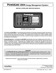
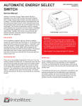
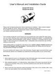
1
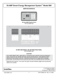
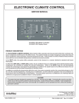
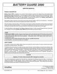
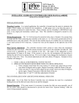
SINGLE DISCONNECT BATTERY CONTROL CENTER
SERVICE MANUAL
Int
ell
ite
c
DC
( F P POW
US AR ER
ES T# M
AN 0 0 - AN
D 0 10 AG
RE 8 EM
LA 7-0 E
YS 00 NT
IN
SID
E)
ry
tte ct
Ba o n n e
c
D is
is
ass
Ch attery
B
ach
Co tery
t
Ba
Part No.'s 00-01087-000
Product Description
The Battery Control Center is a centralized power switching, fusing, and distribution center. Power from the
main and the auxiliary batteries is fed into the Battery Control Center. The full power of both batteries is
available at the box. The system consists of a Battery Disconnect Relay, a bi-directional battery charging
circuit, an auxiliary start function (to provide a "jump start" from the auxiliary battery), and ignition power
switching.
CAUTION:
All servicing of the Battery Control Center should be done only by a qualified Service Technician.
Inadvertent shorts in and around the Battery Control Center could result in severe damage and/or injury.
TOOLS REQUIRED: Low current Test Light, Accurate Voltmeter, (digital read-out preferred).
1485 Jacobs Road
DeLand, Florida 32724
386.738.7307 / 1.800.251.2408
www.intellitec.com
P/N 53-01087-000 Rev. A 071813
SINGLE DISCONNECT BATTERY CONTROL CENTER
SERVICE MANUAL
How The Battery Control Center Works
Battery Disconnect
The Battery Disconnect relay is used to disconnect the auxiliary battery during periods of storage or during
service. The disconnect relay operates by momentarily applying 12 volts to the solenoid coil in either of two
directions: (+12 volts on the "S" terminal and ground on the "I" terminal for opening) and (+12 volts on the "I"
terminal and ground on the "S" terminal for engaging). The actuation voltage is supplied from the auxiliary
battery through the fuse on the disconnect relay. The voltage is supplied to the momentary switch mounted in
the coach and then fed back to the relay on the box. (See Battery Disconnect schematic, Figure 2).
Charging Circuit
The charging circuit, (which utilizes an isolator solenoid to connect the two batteries together for charging) will
charge both batteries if either battery is being charged. It operates by sensing the voltage on the Main and
Auxiliary batteries. If either voltage goes above 13.3 volts (the minimum necessary to fully charge a battery)
for more than 14 seconds, the isolator solenoid will pull in, charging both batteries. If , while the ignition is on,
the voltage falls below 12 volts for more than 4 seconds, the isolator relay will open, keeping all of the
alternator's output available for the chassis functions. If the ignition is off and the auxiliary battery voltage
should drop below 12.8 volts (voltage of a fully charged battery) for 4 seconds, the isolator relay will open,
preventing the coach loads from discharging the main battery. (See Charging Circuit/Aux Start schematic,
Figure 3).
Auxiliary Start
The Auxiliary Start function is used to provide a "jump start" from the auxiliary battery in the event that the main
battery does not have sufficient charge to start the engine. It operates by momentarily connecting the main and
the auxiliary batteries together through the isolator relay. This function is accomplished by pressing the dash
mounted switch, which applies 12 volts to the isolator relay coil. (See Charging Circuit/Aux Start schematic,
Figure 3).
Ignition Switched Power
The ignition circuits are switched by an on-board relay to supply power to the ignition switched circuits. The
power for this relay coil comes from the ignition switch through J2, pin 2. (See Charging Circuit/Aux Start
schematic, Figure 3).
Circuit Breakers
There are two 30 Amp circuit breakers located near the box, that are used to protect the wiring between the
Auxiliary battery and the converter. These breakers have manual reset buttons that pop out when they are
tripped. Contact our sales department if the breakers are not present. (See Figure 4)
1485 Jacobs Road
DeLand, Florida 32724
386.738.7307 / 1.800.251.2408
www.intellitec.com
2
P/N 53-01087-000 Rev. A 071813
SINGLE DISCONNECT BATTERY CONTROL CENTER
SERVICE MANUAL
Trouble Shooting
The Battery Control Center is built in two "layers", the printed circuit board and the relays. The unit has been
designed so that nearly ALL trouble shooting can be done without the removal of the printed circuit board.
Read and understand the trouble shooting procedure first before EVER removing the printed circuit
board.
Checking Fuses
The fuses protecting the main and auxiliary battery power are located on the printed circuit board and are easily
visible for testing and replacement. The fuses for the battery disconnect are located on the relay. The fuses
can be checked either visually or with a test light. To check the fuses visually: Remove the suspected fuse and
examine it for damage to the fusing element. To check using a test light: Ground the test light to a convenient
ground. Check for power on both sides of the fuse. If applicable, make sure Battery Disconnect Relay is on
when checking fuses.
Checking the Battery Disconnect
The Battery Disconnect relay coil terminals are available on the front of the relay.
To engage a relay, momentarily apply +12 volts to the "I" terminal, and the "S" terminal is grounded. The relay
should "click" and latch in. To open the relay, momentarily apply +12 volts to the "S" terminal and the "I" terminal
is grounded. The relay should "click" and then open.
Isolator Relay
An isolator relay is provided on the unit to connect the main and auxiliary batteries together for charging. It also
is used to connect the two batteries together for auxiliary start. This allows the auxiliary battery to be used to
"jump start" the main battery if it doesn't have enough charge to start he engine.
Circuit Breakers (Contact our sales department if the breakers are not present)
The converter circuit breakers, which are in parallel, carry the current between the Auxiliary battery and the
converter. If the coach is not being supplied 120 volts AC, the current is flowing from the battery to the
converter. If the coach is being supplied 120 volts AC, the converter is usually charging the batteries and the
current will flow from the converter to the batteries. If there is a fault or overload between the converter and the
batteries, the circuit breakers will open as indicated by the reset buttons being popped out. To reset the
breakers, turn off the 12 loads and push the buttons in until they latch.
1485 Jacobs Road
DeLand, Florida 32724
386.738.7307 / 1.800.251.2408
www.intellitec.com
3
P/N 53-01087-000 Rev. A 071813
SINGLE DISCONNECT BATTERY CONTROL CENTER
SERVICE MANUAL
Printed Circuit Board Removal
In the event that the printed circuit board needs to be removed, the following procedure should be followed.
1) Remove the negative wires from both batteries to prevent injury to individuals and the equipment.
Be sure that these wires stay clear of the battery posts. Remove power to the converter.
2) Remove the cover, and pull chassis harness plugs from connectors, J4 and J2.
3) Disconnect the battery cables from the coach battery, chassis battery and battery disconnect studs,
being careful to be sure the studs do not rotate.
4) Disconnect the ground wire from J6.
5) Disconnect the wires from the board at J5 and J3.
6) Remove the PCB mounting screws, and the coach battery nut (J1) attached to the printed circuit board.
The unit should be free..
7) Remove the board.
Printed Circuit Board Replacement
Replace the board in the reverse order from the removal.
1485 Jacobs Road
DeLand, Florida 32724
386.738.7307 / 1.800.251.2408
www.intellitec.com
4
P/N 53-01087-000 Rev. A 071813
SINGLE DISCONNECT BATTERY CONTROL CENTER
SERVICE MANUAL
J5
J6**
** CAUTION: To prevent burning of ground foil trace on PCB Assembly
Remove spade terminal that is connected to Ground, before disconnection or installing
battery cables.
Top of board as seen with cover removed.
Figure 1
1485 Jacobs Road
DeLand, Florida 32724
386.738.7307 / 1.800.251.2408
www.intellitec.com
5
P/N 53-01087-000 Rev. A 071813
SINGLE DISCONNECT BATTERY CONTROL CENTER
SERVICE MANUAL
Troubleshooting
Battery Disconnect
A. The relay fails to operate.
1. Batteries may be dead. Check for voltage at the "battery" terminal of the relay. The voltage
should be at least 11 volts. If the voltage is less, charge either battery. If the voltage is more
than 11 volts, continue.
2. The fuse on the relay may be blown. Check the fuse. Replace fuse if the necessary.
3. Wiring or switch may be faulty. To check the operation, have an assistant operate the Battery
Disconnect switch inside the coach. Check for voltage on the "I" terminal and ground on the
"S" terminals at the test points on the printed circuit board.
4. Disconnect Relay may be faulty. If at least 11 volts is available on the "I" or "S" terminal and the
relay fails to operate, replace the relay.
B.
Coach functions operate when coach is plugged in, but not from the battery.
1. Circuit breakers feeding converter may be open. Reset circuit breakers at box.
Charging Circuit
A. Auxiliary battery does not charge.
1. The isolator relay may not be closing. Operate the engine at a high idle for at least twenty (20)
seconds and check the chassis battery voltage. The voltage must be at least 13.3 volts before
the isolator activates. Check the alternator if the voltage is less than 13.3 volts.
Check for voltage on the coil terminal of the isolator relay. If there is no voltage on the coil,
check fuse F5 and replace if necessary. If F5 is good, replace the printed circuit board. If there
is voltage on the coil, check for voltage between the main and auxiliary batteries.
If the voltage is more than 0.1volts replace the relay.
B. Main battery continues to drain.
1. Isolator relay may be bad. Check for voltage on the solenoid coil lead which is available on J1-5,
when the engine is off. If there is no voltage, replace the relay.
1485 Jacobs Road
DeLand, Florida 32724
386.738.7307 / 1.800.251.2408
www.intellitec.com
6
P/N 53-01087-000 Rev. A 071813
SINGLE DISCONNECT BATTERY CONTROL CENTER
SERVICE MANUAL
Troubleshooting
C. Main battery doesn't charge from converter.
1.The converter is not putting out at least 13.3 volts. Check converter, turn off excess 12 volt
loads, if necessary.
2. Converter circuit breakers in Battery Control Center open. Reset the breakers located near the box.
Auxiliary Start
A. Auxiliary Start fails to operate.
1. Fuse 17 may be blown. Check F17.
2. The Auxiliary battery may be dead. Charge battery.
3. Isolator relay may be defective.
4. Switch or wires may be faulty. Check for 12 volts at J4 pin 2, while pushing switch.
If 12 volts is not available, check wiring, if OK, replace the switch.
Ignition Relay
A. The auxilairy powered functions do not operate.
1. Check for 12 volt ignition power coming into printed circuit board on plug J4, pin 11.
2. Check respective fuse.
3. Check for faulty wiring from the ignition switch.
1485 Jacobs Road
DeLand, Florida 32724
386.738.7307 / 1.800.251.2408
www.intellitec.com
7
P/N 53-01087-000 Rev. A 071813
SINGLE DISCONNECT BATTERY CONTROL CENTER
SERVICE MANUAL
Fuses
The fuses used on the Battery Control Center are a standard, plastic "ATO", blade (automotive) type. There are
10 positions for fuses on the board. These are fed from five main sources: the Disconnect-Switched Main
Battery, Ignition-Switched Main Battery, Disconnect-Switched Auxiliary Battery, and the Auxiliary Battery.
The 10 fuses and their size are as follows:
Fuses:
Fuse No.
F1
F2
F3
F4
F5
F6
F7
F8
F9
F10
Function
Reverse Ign
Ign Sw
Ign Sw
Ign Sw
Aux Start Sw
Spare
Spare
Spare
Spare
Step Power
Fuse Size
15 Amp
7.5 Amp
15 Amp
10 Amp
5 Amp
10 Amp
15 Amp
15 Amp
15 Amp
25 Amp
Source
Main Bat
Main Bat
Main Bat
Main Bat
BIRD
Disconnected Aux Bat
Disconnected Aux Bat
Disconnected Aux Bat
Disconnected Aux Bat
Disconnected Aux Bat
Connection
J2 - 6
J2 - 5
J2 - 4
J2 - 3
J2 - 2
J4 - 1
J4 - 4
J4 - 3
J4 - 2
J4 - 1
Battery Disconnect Fuses:
There are two 5 Amp fuses located on the battery disconnect relay. One of these protects the power lead going
to the coach mounted switch and the other protects the lead powering the indicator on the switch panel.
Circuit Breakers
There are two 30 Amp type III (manual reset), circuit breakers. They are connected to the Auxiliary battery
through the Disconnect relay. These breakers are intended to connect to the converter and fuse panel within
the Auxiliary. These circuit breakers are located near the box. To reset the breakers, press the buttons on the
ends. Contact our sales department if the breakers are not present.
1485 Jacobs Road
DeLand, Florida 32724
386.738.7307 / 1.800.251.2408
www.intellitec.com
8
P/N 53-01087-000 Rev. A 071813
SINGLE DISCONNECT BATTERY CONTROL CENTER
SERVICE MANUAL
Plugs - Pins & Functions
J1 - Auilary Battery Input
J2 - (6 pin) Mate-N-Lok
Pin
1
2
3
4
5
6
(Mating Housing Amp 640585-1)
Function
Aux. Start Switch
Ignition Input
Ignition Switched Power
Ignition Switched Power
Ignition Switched Power
Inverted Ignition Switched Power OR Main Battery
Fuse
F4
F3
F2
F1
J3 - Main Battery Input
J4 - (5 pin) Mate-N-Lok
Pin
1
2
3
4
5
(Mating Housing Amp 1-480763-0)
Function
Power Step
Auxilairy Battery Power
Auxilairy Battery Power
Auxilairy Battery Power
Auxilairy Battery Power
Fuse
F10
F9
F8
F7
F6
J6 - Ground
1485 Jacobs Road
DeLand, Florida 32724
386.738.7307 / 1.800.251.2408
www.intellitec.com
9
P/N 53-01087-000 Rev. A 071813
SINGLE DISCONNECT BATTERY CONTROL CENTER
SERVICE MANUAL
Figure 2
1485 Jacobs Road
DeLand, Florida 32724
386.738.7307 / 1.800.251.2408
www.intellitec.com
10
P/N 53-01087-000 Rev. A 071813
SINGLE DISCONNECT BATTERY CONTROL CENTER
SERVICE MANUAL
Figure 3
1485 Jacobs Road
DeLand, Florida 32724
386.738.7307 / 1.800.251.2408
www.intellitec.com
11
P/N 53-01087-000 Rev. A 071813
SINGLE DISCONNECT BATTERY CONTROL CENTER
SERVICE MANUAL
Figure 4
1485 Jacobs Road
DeLand, Florida 32724
386.738.7307 / 1.800.251.2408
www.intellitec.com
12
P/N 53-01087-000 Rev. A 071813