1
TEMP-AIR
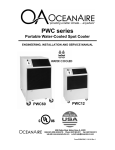
Portable Water-Cooled Spot Cooler
ENGINEERING, INSTALLATION AND SERVICE MANUAL
PWC60
PWC12
R410A Models
3700 W Preserve Blvd. Burnsville, MN 55337
(800) 836-7432 www.Temp-Cool.com
TABLE OF CONENTS
PAGE
GENERAL DESCRIPTION ….................................
1
PRODUCT DATA AND SPECIFICATIONS............
2
UNIT DESCRIPTION
Standard Features..................................
3
Applications / Operation..........................
4
Electrical..................................................
5
Use of Extension Cords..........................
6
Accessories………...................................
7 - 12
Options....................................................
13
Installation................................................
14
Thermostat...............................................
15
Water Valve Adjustment..........................
16
SERVICE
Replacement Parts Procedure.................
17
Troubleshooting Guide.............................
18
Preventive Maintenance...........................
19
DIAGRAMS
Unit Interior................................................
20
Piping Schematic.......................................
21
Three Phase Monitor..................................
22
Wiring Diagrams.........................................
23 - 27
FORWARD
This manual provides the user with basic details for the installation
and operation of the TEMP-AIR spot cooler. It is recommended
to read and fully understand the instructions outlined within
this manual, before operating the TEMP-AIR unit.
As with all commercial air conditioning equipment, it is recommended
to have the TEMP-AIR unit sized and installed by a licensed specifying
engineer and contractor, in accordance with all local and state codes.
The length of service received can be extended by following the
installation and preventive maintenance instructions.
NOTICE
In our ongoing process of continuous improvement, the items and
procedures described in this manual are subject to change without
notice. Please note model and serial number of the TEMP-AIR unit
when contacting the factory.
GENERAL DESCRIPTION
The TEMP-AIR portable water-cooled air conditioner is designed for
permanent or temporary spot cooling applications. The entire air
conditioning unit has been built in an attractive sheet metal cabinet,
equipped with heavy-duty casters for mobility. All TEMP-AIR
models come with a 10-foot power cord for electrical connection and
added mobility in service. These spot-coolers are designed to direct
air to specific areas or objects through a discharge grill located on
the upper-front of the unit, while rejecting heat from the top of the
unit. The TEMP-AIR water-cooled models range in cooling capacities
from 12,000 BTU/HR to 60,050 BTU/HR to satisfy most space cooling
requirements.
The TEMP-AIR spot cooler is a self-contained unit with the entire
cooling system, fan motors and electrical components neatly arranged
in a gray polyester powder coated metal cabinet. When connected to the
proper source of electrical power, a 24-volt thermostat controls the
TEMP-AIR unit to provide the desired level of comfort and cooling.
A wide variety of accessories and factory installed options are available for the TEMP-AIR units allowing for improved performance and
versatility.
NOMENCLATURE
P WC 24 1 2
PORTABLE
VOLTAGE
WATER-COOLED
SINGLE PHASE
NOMINAL CAPACITY
CAPACITY RATING
NOMINAL CAPACITY
12..........12,000 BTU/HR
18..........18,000 BTU/HR
24..........24,00 BTU/HR
36..........36,000 BTU/HR
60……...60,000 BTU/HR
WARRANTY CARD
It is important that the warranty card be filled out completely and
returned to the factory within fourteen (14) days of installation of the
unit in order to receive the benefits of the warranty.
1
SPECIFICATIONS
1. Nominal capacity is total BTUH at 80ºDB/67ºWB return
air, high fan speed, with 85ºEWT to 95ºLWT (3 GPM per Ton)
2. CFM with free discharge
3. Sound Pressure, dB at 5 feet, commercial operation
4. 3/8” water valve on models 12, 18, 24 (with 3/8” flare fitting),
3/4” water valve on models 36, 60 (with 5/8” flare fitting)
5. Amps and Watts at 208 Volts
6. Time delay fuses/circuit breakers are recommended
Ambient operating range 65º to 105º
May operate to 55º if equipped with optional hot gas bypass
(factory installed)
WATER CONNECTIONS
For Model 12, C1 = WATER OUT, C2 = WATER IN
For Models 18, 24, 36 & 60, C1 = WATER IN, C2 = WATER OUT
50 Hz MODELS AVAILABLE - CONSULT FACTORY
2
CABINET
STANDARD FEATURES
The unit's cabinet is constructed of 18 gauge steel with a gray polyester powder
coated finish that will compliment any decor. The entire cabinet is insulated with a soundabsorbing insulation for cool, quiet comfort. All units come equipped with handles and
swivel casters for portability and convenient set-up.
ELECTRONIC THERMOSTAT
All units are equipped with a non-programmable electronic thermostat. When
power is connected to the unit, the thermostat will control the unit to cool a space to the
desired temperature. The thermostat is also capable of controlling the fan to operate
automatically (when needed) or continuously. To protect the compressor from shortcycling, there is a built-in, 4-minute time delay in the thermostat.
FAN SPEED CONTROL
A two position rocker switch, located next to the thermostat, provides the user with the
option of running the evaporator fan in high-speed or low-speed.
CONDENSATE PUMP
All units come equipped with an Automatic Condensate Pump that disposes of
the condensate. The pump discharges through a 3/8 male falre connection located on
the back of the unit. The automatic pump is capable of a 20ft lift, to handle just about any
installation requirement.
CONDENSATE ALARM LIGHT
On the front of all water-cooled models, there is a Condensate Alarm Light (RED) located
near the thermostat. For models less than 5-tons, the light indicates that the condensate
tank is full and needs to be emptied. In the 5-ton units (model PAC60) the light
indicates a condensate pump over-flow condition where the pump is either disabled, or
incapable of rejecting the condensate water, and must be serviced.
FILTERS
All water-cooled units are equipped with washable filters at the air intakes. 1/8” mesh air
filters located behind the evaporator return air grill serve to filter the air before it is cooled.
The filters can be easily removed and cleaned.
HIGH PRESSURE SAFETY SWITCH
Located on the back of the unit is a manual re-set high pressure switch, used
for the protection of the compressor in the event that the condenser water supply is
turned off. If the condensing pressure exceeds the limit setting, the cut-out shuts down
the compressor, while the evaporator fan remains running. The compressor can be restarted, once the condensing pressure has lowered, by depressing the “RESET” button.
POWER CORDS
All TEMP-AIR portable water-cooled units come with power cords, convenient connection
and portability. All units except the 5-ton models, and 3-phase models are equipped with
LCDI for added safety devices.
3
APPLICATIONS
SPOT COOLER
This series can be used in an open environment to cool specific objects
or "spots". Spot Cooling is a convenient and economical way to provide air
conditioning where cooling the entire space is impractical. Cool air is
discharged from the unit and is directed where it is needed. Nozzle kits can
be used to improve direction of the cooling airflow.
ROOM AIR CONDITIONER
One feature of the water-cooled model is it operates as a room air conditioner
because water is used as the means for heat rejection. The major convenience
of water-cooled air conditioning is the convenience of connecting water hoses
or lines as compared to the installation of condenser air ducts used for aircooled portables. A variety of hose kits are available that can be used for
connecting to a water supply and drain while providing portability within the
conditioned space.
OPERATION / DESCRIPTION
EVAPORATOR
FAN DISCHARGE
“COOL”
FAN SPEED
SWITCH
THERMOSTAT
GRILL
AND FILTER
RETURN
AIR
INLET
DRAIN
WATER IN
WATER OUT
FRONT VIEW
4
SERVICE CORD
All TEMP-AIR water-cooled series units are equipped with the standard ten foot long service
cord with plug configurations and receptacle requirements as shown in this chart. PWC1011,
PWC1211, PWC1811, PWC2412 and PWC3612 units come with LCDI (Leakage Current
Detection & Interruption) devices that serve as a means of electrical protection.
CAUTION—DO NOT USE THE LCDI AS AN ON/OFF SWITCH FOR THE UNIT
All 3-phase models are equipped with locking plugs for added connection reliability. Refer to the chart below for plug and receptacle details for all series models.
A DAMAGED LCDI POWER SUPPLY CORD MUST BE REPLACED
WITH A NEW POWER SUPPLY CORD OBTAINED FROM
TEMP-AIR AND NOT REPAIRED
UNIT/MODEL
PLUG CONFIGURATION
RECEPTACLE
115 VOLT
PWC1211
PWC1811
15A-125 VOLT
NEMA 5-15P
NEMA-5-15R
208-230 VOLT SINGLE PHASE
PWC2412
PWC3612
20A-250 VOLT
NEMA 6-20P
NEMA 6-20R
30A-250 VOLT
NEMA 6-30P
NEMA 6-50R
20A-250 VOLT
NEMA L15-20P
NEMA L15-20R
PWC6032
30A-250 VOLT
NEMA L15-30P
NEMA L15-30R
460 VOLT 3-PHASE
PWC3634
PWC6034
20A-460 VOLT
NEMA L16-20P
NEMA L16-20R
208-230 VOLT SINGLE PHASE
PWC6012
208-230 VOLT 3-PHASE
PWC3632
208-230 VOLT 3-PHASE
5
USE OF EXTENSION CORDS
CAUTION:
FOR MODEL PWC1211 AND PWC1811 AN EXTENSION CORD CAN BE
USED PROVIDED IT IS RATED AT LEAST 15 AMPS @ 115 VOLTS WITH
GROUNDING-TYPE ATTACHMENT PLUG AND GROUNDING TYPE
CONNECTOR (LOAD FITTING)
FOR MODELS PWC2412 AND PWC3612 AN EXTENSION CORD CAN BE
USED PROVIDED IT IS RATED AT LEAST 20 AMPS @ 250 VOLTS WITH
GROUNDING-TYPE ATTACHMENT PLUG AND GROUNDING TYPE
CONNECTOR (LOAD FITTING)
FOR MODEL PWC6012 AN EXTENSION CORD CAN BE USED PROVIDED IT IS RATED AT LEAST 30 AMPS @ 250 VOLTS WITH GROUNDING-TYPE ATTACHMENT PLUG AND GROUNDING TYPE CONNECTOR
(LOAD FITTING)
FOR MODEL PWC3632 AN EXTENSION CORD MAY BEUSED PROVIDED IT IS RATED AT LEAST 20 AMPS @ 250 VOLTS, 3 PHASE
FOR MODEL PWC6032 AN EXTENSION CORD MAY BEUSED PROVIDED IT IS RATED AT LEAST 30 AMPS @ 250 VOLTS, 3 PHASE
FOR MODELS PWC3634 AND PWC6034 AN EXTENSION CORD CAN BE
USED PROVIDED IT IS RATED AT LEAST 20 AMPS @ 600 VOLTS, 3
PHASE
SPECIAL NOTICE—THREE PHASE OPERATION
Models PWC3632, PWC3634, PWC6032 and PWC6034
All three-phase AQUACOOLER models are equipped with a threephase monitor for added compressor protection. The phase monitor,
located in the control box, has multi-color LED that reports status.
The monitor protects the compressor from reverse operation, phase
loss and low voltage situations. Further description of the threephase monitor is located in the electrical section of the manual.
NOTICE - DO NOT OPERATE ANY THREE-PHASE UNIT BY BYPASSING THE MONITOR, THIS WILL VOID THE WARRANTY
6
ACCESSORIES
DDA-6
DDA-10
2DDA-16
DDA-16
NK-1
NK-2
2NK-3
NK-3
DEP-10
DEP-12
DEP-16
HK-1
HK-2
HK-3
HK-4
HK-5
HK-6
WATER-COOLED UNIT
7
ACCESSORIES
NOZZLE KIT
NK-1
(2 X 4-Inch)
NK-2
(2 X 6-Inch)
2NK-3
(2 x 8-iNCH)
NK-3
(2 X 8-Inch)
PWC12
PWC18, 24
PWC36
PWC60
EVAPORATOR RETURN AIR PLENUM
DEP-10 (10-Inch Round)
PWC12
DEP-12 (12-Inch Round)
PWC18, 24
DEP-16 (16-Inch Round)
PWC36, 60
DISCHARGE DUCT ADAPTER
DDA-6
(6-Inch Round)
PWC12
DDA-10 (10-Inch Round)
PWC18, 24,
2DDA-16 (12-inch Round)
PWC36
DDA-16 (16-Inch Round)
PWC60
HOSE
HK-1
HK-2
HK-5
KIT
10FT
25FT
40FT
PWC 12, 18, 24
PWC 12, 18, 24
PWC 12, 18, 24
HK-3
HK-4
HK-6
10FT
25FT
40FT
PWC 36, 60
PWC 36, 60
PWC 36, 60
8
ACCESSORIES
DISCHARGE AIR NOZZLE KIT ASSEMBLY (NK, 2NK)
The optional discharge nozzle kits are used to direct the conditioned air to a specific target area. By concentrating the airflow, the nozzles increase the air velocity towards
production lines to cool personnel or equipment. In server rooms, the nozzles can be
used to induce airflow through the rack to remove the hot air from the area of the equipment.
NK-1 for model PWC12, with (2) 4-inch diameter nozzles with an approximate
compressed length of 15 inches. The approximate extended length is 21 inches.
NK-2 for models PWC18, PWC24 with (2) 6-inch diameter nozzles with an approximate
compressed length of 22 inches. The approximate extended length is 32 inches.
2NK-3 for model PWC36 with (2) 8-inch diameter nozzles with an approximate
compressed length of 20 inches. The approximate extended length is 29 inches.
NK-3 for model PWC60, with (2) 8-inch diameter nozzles with an approximate
compressed length of 20 inches. The extended length is approximately 29 inches.
The nozzle kits come pre-assembles with the nozzles secured to a mounting plate, and
with edge guards. By removing the unit's discharge grill, one can insert the nozzle kit
into the opening without the use of tools.
Nozzle Kits
9
ACCESSORIES
EVAPORATOR RETURN AIR PLENUM, DEP
Evaporator return air plenums are available for installations where it is required
to duct air to the inlet of the evaporator. The evaporator return air plenums allow
the user to connect round duct (flexible or rigid) to the return air intake to reduce
air noise and increase the number of options for solving difficult cooling
problems. The plenum attaches to the front of the unit, replacing the return air
grill. Refer to the table below for configuration and application information
DEP-10 for PWC12 transitions the return air opening to 10-inch round duct.
DEP-12 for PWC18 and PWC24 transitions the return opening to a 12-inch
round duct.
DEP-16 for PWC36 and PWC60 transitions the return opening to a16 inch
round duct.
NOTE—When a DEP is installed, it is recommended to set the evaporator
blower speed to high, to avoid evaporator freeze-up.
FILTER(S)
DEP—EVAPORATOR
RETURN AIR PLENUM
Plenum Kit
PWC12 PWC18 PWC24 PWC36
Duct/Flange
PWC60
FILTERS
DEP-10
10 inch
(1) 10”X20”X1”
DEP-12
12 inch
(1) 15”X25”X1”
DEP-16
16 inch
(1) 12”X30”X1”
(1)15”X30”X1”
Maximum
Equivalent
Feet
25
50
50
50
100
Est.
External
Static
Pressure
(.20)
(.25)
(.25)
(.25)
(.50)
10
ACCESSORIES
Discharge Duct Adapter, DDA, 2DDA
Discharge duct adapters are available for applications where ducted evaporator discharge
is required. The adapters can be easily installed on the unit without fasteners, and be
installed for either vertical or horizontal ducting. The standard discharge grille is removed
and the DDA is attached in the grill opening.
DDA-6 for PWC12, converts the evaporator discharge to a 6-inch diameter round duct.
DDA-10 for PWC18 and PWC24 converts the evaporator discharge to a 10-inch diameter
round duct.
2DDA-16 for PWC36 models, converts the evaporator discharge to a 16-inch diameter
round duct.
DDA-16 FOR PWC60 models, converts the evaporator discharge to a 16-inch round duct.
When used in conjunction with the evaporator return air plenum, DEP, the unit can provide closed-loop cooling to and from a given space without the influence of any outside
air.
NOTE—When a DDA is installed, it is recommended to set the evaporator blower
speed to high, to avoid evaporator freeze-up.
Adapter
Model
Round
Duct Size
DDA-6
6-inch
DDA-10
10-inch
2DDA-16
16-inch
DDA-16
16-inch
PWC12
PWC18
PWC24
PWC36
PWC60
Maximum Approx
Equivalent Feet
25
50
50
50
100
Maximum
E.S.P
.15
.25
.25
.25
.50
11
ACCESSORIES
Hose Kit, HK
Hose kits are available in lengths of 10, 25, and 40 feet. Each hose
kit allows for convenient installation of the unit, while allowing
for portability within the allowable space.
NOTICE—When using these hoses in applications with water
pressures exceeding 50 PSIG, a water pressure reducing valve
must be installed in the water supply line prior to the hose kit;
otherwise warranty on the hose kits will be void.
All hose kits have FEMALE flare connectors to match the MALE flare
fittings on the units (see chart below). The WATER IN connector
consists of a 3/4” hose barb. WATER OUT and DRAIN (condensate)
have no fitting, and can be fed to a sink or permanent drain. When
using a hose kit, avoid sharp corners, hot water pipes and kinking to
assure proper water flow of the supply and return lines.
Included with the hose kit is a sink/faucet adapter
Hose Kit Length
Flare Conn
PWC12 PWC18 PWC24 PWC36 PWC60
IN-OUT-DRAIN
HK-1
10 ft
3/8
3/8 3/8
HK-2
25 ft
3/8
3/8 3/8
HK-5
40 ft
3/8
3/8 3/8
HK-3
10 ft
5/8
5/8 3/8
HK-4
25 ft
5/8
5/8 3/8
HK-6
40 ft
5/8
5/8 3/8
Hose Kit
12
OPTIONS
In some applications, units can be manufactured with optional components for added
performance and longevity. Below are a few of the options that are available
for units.
Consult your distributor for pricing and availability.
TOWER UNITS
In applications where the unit is connected to a closed-loop condenser water circuit, a unit can be built for direct water connection without a water valve.
HIGH PRESSURE WATER VALVE
For applications where water supply pressures exceed 150 psig, a high pressure water
regulating valve can be installed in the unit. Valves designed for use with up to 350
psig water inlet pressure, are available.
CUPRO-NICKEL CONDENSER
When chemically treated water, salt water or brine is used in the condenser coil, it is recommended that the unit be equipped with a 90/10 Cupro-Nickel condenser coil.
ACRYLIC TREATED EVAPORATOR COIL
When airborne contaminants are a problem for air conditioning applications, acrylic
coated evaporator coils are recommended to guard against pitting or corroding.
HERESITE TREATED EVAPORATOR COIL
For use in chemically corrosive environments, the unit can be manufactured with a
Heresite® coated evaporator coil for improved coil life.
HOT GAS BYPASS VALVE
In applications where low evaporator temperatures may occur, an optional hot gas bypass valve can be installed to regulate the evaporator temperature. The bypass valve
feeds refrigerant (hot gas) into the evaporator to avoid freeze-ups.
13
INSTALLATION INSTRUCTIONS
RECEIVING—INSPECTION:
Upon receiving your water-cooled unit, inspect the packaging for any
damage. All units are shipped on a skid, and packaged in a triple-wall
carton for added protection. In shipment, some wear may occur on the
packaging. If the packaging is heavily damaged or broken, file a claim
with the freight company immediately. Carefully unpack the unit and
remove all wrapping materials. Save all documentation and fill out the
Warranty Card and mail it to TEMP-AIR.
BEFORE INSTALLING
Check the air conditioner/spot cooler for any damage. All TEMP-AIR
products are thoroughly inspected at the factory and carefully
packaged. If any damage is evident, file a claim with the delivering
carrier immediately.
ELECTRICAL REQUIREMENTS
Check the nameplate located on the back of the unit to make certain
that the proper power is available for the unit. Refer to "Specifications"
section for voltage and amperage requirements. For proper NEMA
receptacles, refer to "Electrical service plug configuration". When using
extension cords, use the properly sized cord as specified, and check
cord voltage to the unit.
TIME DELAY FUSES/CIRCUIT BREAKERS ARE RECOMMENDED
WARNING—OPERATING THE UNIT ON
IMPROPER VOLTAGE WILL VOID THE
WARRANTY
ACCESSORIES
Verify that all accessories are correct for the model, and that they
installed in accordance with all instructions.
START-UP
Install the unit in accordance with all local and state building codes, and
install all accessories. Allow for a clearance around the unit for future
maintenance and/or service. Level unit and lock casters, when
available. Connect power and test the LCDI on the power cord (if
available). Power up unit, via thermostat and check for proper
operation. Refer to Thermostat Operation for more details.
14
FAN
THERMOSTAT OPERATION
When the power is connected, the LCD screen on the thermostat will illuminate. Pressing
the FAN button once, will turn on the evaporator fan blower. To turn the blower off, push
the FAN button once again.
COOLING MODE Ä
To operate unit for cooling, push MODE button to display COOL in the window.
Push down arrow button multiple times to lower set point to desired temperature.
The display will show the set-point temperature for 5 seconds, then it will return to room
temperature display.
After a slight pause, the fan motor and compressor will start, beginning the cooling cycle.
Remember, the set-point must be lower than the room temperature for the unit to start.
72
MODE
COOL
OUTDOOR
DAY/NIGHT
FAN
WAIT 4 MINUTES
BEFORE RE-STARTING
The OUTDOOR and DAY/NIGHT buttons are not used and do not effect unit operation.
This is a cooling only thermostat. Select the temperature you want by pressing the ▲ or
▼ buttons. The word COOL and the temperature set-point is displayed for 5 seconds.
To change display to Celsius, simultaneously press the ▲ and ▼ buttons. Press them
again to change back to Fahrenheit.
No batteries are required. In the event of a power failure, when the power is restored the
thermostat will continue operating as if the power had never been off.
Compressor short cycle protection is built-in to the thermostat. A 4-minute time delay will
protect the unit.
15
WATER VALVE ADJUSTMENT
All water-cooled units come equipped with automatic pressure regulated water valves, that
control the condenser water flow rate. The water valves will open when the system is
running and will adjust the water flow rate as required by the air conditioning system.
In some cases, water temperatures can cause the valve to open and close at a high rate,
causing a “chattering” condition in the water supply line. In these cases, it is recommended that the water valve be adjusted.
1. Disconnect the unit power.
2. Remove the unit back panel and locate the water regulating valve in the lower right
region of the unit.
3. Locate the water valve adjustment screw. At the top of the valve there is a squareshaped adjustment screw.
4. Turn the adjustment screw 1/4 turn, re-start the unit, and observe operation to see if
the “chattering” goes away. Make 1/4 turn adjustments and observe the unit operation
until the condition goes away.
5. Close up the unit and POWER
Water Valve
Adjustment Screw
16
REPLACEMENT PROCEDURE FOR PARTS
IT IS RECOMMENDED THAT ALL TEMP-AIR UNITS BE SERVICED BY A
LICENSED TECHNICIAN
WARNING—TO AVOID INJURY, DISCONNECT UNIT POWER PRIOR TO SERVICING
A. FAN MOTORS
1. Remove cabinet's left-side panel (when looking at the front of the unit).
2. Evaporator fan motor—disconnect evaporator motor wires from evaporator fan
contactor and fan speed rocker switch. Condenser fan motor—disconnect condenser
motor wires from condenser fan contactor.
3. For all model sizes 12, 18 and 36, remove the screws securing motors and inletring to blower housings (all screws are external and visible), and remove blower wheelmotor assembly. Remove the blower wheel set screw and disassemble the blower
wheel from the motor shaft and remove the motor.
For models size 60—loosen blower wheel shaft set screw, and remove the screws
securing the motor mount to the blower housing and remove motor and mount.
Remove the motor from the motor mount.
4. Install the new motor, reversing the removal procedure.
B. THERMOSTAT (NO BATTERIES REQUIRED)
1. Pull up from the bottom of the thermostat to remove it from the mounting sub-base, by
gently prying up on the face plate in the slot at the base of the thermostat. Make sure
small thermistor located in the bottom of the thermostat for temperature sensing, is not
bent or damaged.
2. To remove the thermostat sub-base, remove the 2 mounting screws and the 3 wires
(red/yellow/green or red/white black). Make sure the 3 wires do not fall into the
cabinet. Install sub-base by reversing removal procedure.
C. TANK FULL LIGHT
To replace the Condensate Alarm Light on all models, disconnect the wires from the
lamp and bend the tinnerman clip retaining light and pull out. Install new light, reversing
the procedure.
D. CONDENSATE PUMP (ON ALL 5-TON UNITS OR ON UNITS WHERE THE
CONDENSATE PUMP KIT HAS BEEN INSTALLED)
1. Open condensate bucket access door located on lower right side panel and locate the
condensate pump.
2. Remove brackets securing condensate pump in base pan, or condensate tank tray pan
3. Disconnect pump wire leads at Molex connectors. Remove retainer clamp and tubing.
4. Replace pump, install by reversing procedure.
E. HIGH PRESSURE SAFETY SWITCH
1. Remove cabinets left hand side panel, or right rear side panel of Model 60.
2. Remove flare nut that secures capillary to the refrigeration system high pressure side.
A Schrader valve is located in the discharge port, and allows removal without dumping
the refrigerant charge.
3. Remove two screws that retain high pressure switch.
4. Disconnect wire leads from compressor contactor and condensate pump safety switch.
5. Install new High Pressure Control, reversing the procedure.
To gain access to compressor and compressor run capacitor, remove left hand side
panel.
17
TROUBLESHOOTING GUIDE
The following steps and procedures are recommended for correcting the
problems indicated. In the event that the problem can not be corrected,
service may be required.
SERVICE SHOULD BE PERFORMED BY A QUALIFIED AIR
CONDITIONING SERVICE TECHNICIAN
PROBLEM: UNIT DOES NOT POWER UP
CAUSE: Power interruption
REMEDY: Check LCDI (on models with LCDI), and reset LCDI. Check
external power supply making sure that the disconnect is ON. Check for
blown fuses or tripped circuit breakers. Reset or replace if needed.
PROBLEM: NO DISPLAY ON THERMOSTAT
CAUSE: Faulty thermostat or faulty transformer
REMEDY: Thermostat may be defective...remove and replace. Transformer
may be defective...remove and replace.
PROBLEM: EVAPORATOR FAN RUNS BUT COMPRESSOR AND
CONDENSER FAN DO NOT START
CAUSE: Thermostat — setting may be too high.
REMEDY: Make sure set-point is lower than room temperature. You should
see a snowflake ”Ä” designating that the thermostat is calling for cooling.
Note—there is a 4 minute time delay for the compressor
CAUSE: Thermostat—Loose wiring
REMEDY: Examine the control unit for loose wires. Tighten any loose
connections.
CAUSE: Condensate Alarm—Check for Condensate Alarm Light.
REMEDY: Check condensate tank and empty tank or check condensate
pump and make sure pump is working properly and that there is no kink in
the drain line from the pump.
CAUSE: High Pressure Cut-out—Check High Pressure Cut-out Switch.
Press Reset and clear away any obstructions to the condenser intake or
condenser discharge.
CAUSE: Low Voltage — Check power supply for voltage outside the range
of 106-126 volts on the 115 Volt unit and 187-253 Volts on the 208/230 Volt
unit.
REMEDY: Have power checked by electrician and repaired.
CAUSE: Compressor contactor open or burned.
REMEDY: Replace contactor
18
PREVENTIVE MAINTENANCE
TEMP-AIR Spot Coolers are designed to last a long time and to give
maximum performance and reliability with minimum maintenance. To
prolong the life of the unit, regular maintenance must be performed
as specified below:
BLOWER MOTORS
The motors on all units have permanently lubricated bearings. No
oiling is necessary
FILTERS
A clogged filter will cause the unit to operate at greatly reduced
efficiencies. We recommend that the filter be inspected on a regular
bases every six weeks or more often depending on the environment.
The evaporator filter is located behind the return air grille and can be
easily removed and cleaned. The filters must be washed periodically
as needed by placing them in a dishwasher or soaking them in a
solution of warm water and detergent for 10 minutes. Then rinsing
them clean with hot water and shaking excess moisture from filter.
CONDENSATE PUMP
Condensate pumps come standard on all water-cooled models. When
servicing pump follow these steps;
1. Make certain that the unit is disconnected from the power source
before attempting to service or remove any component.
2. Be sure the floats move freely. Clean as necessary.
3. Remove the volute and check for obstructions. Clean as needed.
4. Clean the tank with warm water and mild soap when mineral
deposits are visible.
5. Check the inlet and outlet piping. Clean as necessary. Be sure
there are no kinks in the lines that would inhibit flow.
GENERAL
When necessary maintenance steps outlined above are followed, the
air conditioner will provide long and reliable service. The refrigeration
and electrical circuits of the system should only be serviced by a fully
qualified service technician.
19
Evaporator
Blower
High Pressure
Reset Switch
Evaporator
Coil
Water
Valver
Condensate
Pump
Control
Box
Compressor
PWC INTERIOR
20
EVAPORATOR
COIL
SUCTION LINE
EVAPORATOR
BLOWER
AIR
CAPILLARY
TUBES
WATER OUT
FILTER/DRIER
ACCESS
VALVES
HP RESET
CONDENSER
COIL
DISCHARGE LINE
WATER IN
WATER
VALVE
COMPRESSOR
PIPING SCHEMATIC
Water-Cooled Spot Cooler
21
Three Phase Monitor
Three-Phase units can be equipped with monitors for compressor protection.
The TEMP-AIR Three-phase Monitor safeguards the unit against incorrect
compressor rotation, low-voltage and/or loss of power in any one of the power
legs. The monitor is installed in the control box and is equipped with an LED
for diagnosis of an improper electrical condition (see diagrams below). When
power is connected, the compressor WILL NOT power up, until the monitor
start delay has been timed out. If the compressor does not power up, an
electrical condition may need to be addressed. Remove the control box cover
and check the observe the LED on the phase monitor. The LED signals the
following:
GREEN-BLINKING - Start delay, 120 sec.
GREEN - Proper Operation
RED/GREEN-BLINKING signals reverse phase rotation. Switch any two of the
power leads for the unit, NOT THE MONITOR LEADS, and re-start.
RED-BLINKING signals improper voltage and/or phase loss. Correct the
power problem, then re-start the unit.
In the event of a power interruption, the unit will re-set to a start-up condition.
The Phase Monitor will not allow the compressor to start until power is
corrected.
LED
NOTICE
UNIT IS EQUIPPED WITH 3-PHASE POWER
MONITOR (WITH LED)
LED INDICATION
GREEN (BLINKING) = START DELAY
GREEN = PROPER OPERATION
RED/GREEN/BLINKING = PHASE REVERSAL
RED (BLINKING) = IMPROPER LEG VOLTAGE
OR PHASE LOSS
START DELAY = 120 SECONDS
22
7(03$,5
www.temp-cool.com
23
LED
Plug L15-20P
24
208-230V
SINGLE PHASE
Plug 5-30P
25
LED
Plug L15-30P
26
LED
Plug L16-20P
27
USEFUL INFORMATION
MODEL:
SERIAL NUMBER:
DATE PURCHASED:
INSTALLED BY:
For Technical Support, contact TEMP-AIR at (800) 836-7432.
Please indicate the Model Number and Serial Number of the unit
to assure proper information and service parts.
3700 W Preserve Blvd. Burnsville, MN 55337
(800) 836-7432 www.Temp-Cool.com