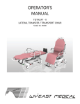
1
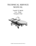
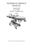
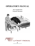
TECHNICAL SERVICE MANUAL The Totalift-PTS Transfer Stretcher PTS Technical Manual 51441 Rev 01 WARRANTY Wy’East Medical Corporation warrants to the original user that the Totalift-PTS Transfer Stretchers manufactured by the company are free from defects in material and workmanship under normal use and service. The term of warranty from the date of purchase/shipment is one (1) year during which Wy’East will provide to the user replacement components or repaired components with the exception of mattress pads, which are warranted for ninety (90) days. In order to initiate a warranty claim the original user must provide prompt notice to Wy’East Medical Corporation within the applicable warranty period specifying the nature of the claim. Wy’East will issue instructions as to the procedure to follow. Wy’East reserves the right to confirm the existence of any claimed defect and to determine whether any damage was caused by neglect, misuse, unauthorized alteration or failure to follow maintenance instructions. With respect to a claim covered by this warranty, the defective part will be replaced or repaired at no charge, provided the defective part is returned to Wy’East Medical. The user has the responsibility for shipping charges and installation. Assistance is available by calling (503) 6573101 in Oregon. This is the exclusive remedy for a claim under this warranty and in no event shall Wy’East be liable for consequential damages. THIS WARRANTY IS IN LIEU OF ALL OTHER WARRANTIES EXPRESSED OR IMPLIED. PLEASE Read this entire manual before operating The Totalift-PTS Transfer Stretcher. This warranty applies to Wy’East Totalift-PTS Transfer Stretcher only. For questions or information regarding other Wy’East products, contact: Wy’East Medical Corporation P.O. Box 1625 Clackamas, Oregon, USA Telephone: (503) 657-3101 (800) 255-3126 FAX: (503) 657-6901 www.wyeastmed.com [email protected] PTS Technical Manual 51441 Rev 01 TABLE OF CONTENTS This manual provides maintenance and service information for the TOTALIFT-PTS Transfer Stretcher. If replacement parts are required, contact WY’EAST MEDICAL with the serial number of your stretcher to ensure the accuracy of replacement parts. DESCRIPTION PAGE # Warranty PTS Specifications PTS Trouble Shooting PTS Periodic Maintenance Mattress Care PTS Assembly Drawings PTS Options PTS Service Kits PTS Forms Unpacking Instructions Contact Information Inside Front Cover Page 2-4 Page 5-6 Page 7 Page 8 Page 9-30 Page 31-36 Page 37-41 Page 42-43 Page 44 Back Cover Consistent with our policy of continuing product improvement, WY’EAST MEDICAL reserves the right to change these specifications without notice or obligation. PTS Technical Manual 51441 Rev 01 SPECIFICATIONS Maximum Length Maximum Width PTS Technical Specifications 82.00 in / 208.28 cm 32.25 in / 81.92 cm Mattress Length Mattress Width 76.50 in / 194.31 cm 30.00 in / 76.20 cm Siderail Length Siderail Height Siderail Width 60.75 in / 154.31 cm 11.50 in / 29.21 cm 30.50 in / 77.47 cm Maximum Height Minimum Height 37.50 in / 94.62 cm 24.75 in / 62.87 cm Wheelbase Length Wheelbase Width Transfer System Travel Attached IV Pole Height 47.00 in / 119.38 cm 26.25 in / 66.68 cm 22.00 in / 55.88 cm 49.00 in / 124.46 cm Fowler Travel Trendelenberg Travel Maximum Patient Weight PTS Stretcher Weight 80° 8.5° / 8.5° 600 lbs / 272.16 kg 340 lbs / 154.22 kg PTS Technical Manual 51441 Rev 01 Page 2 SPECIFICATIONS PTS Technical Manual 51441 Rev 01 Page 3 SPECIFICATIONS PTS Technical Manual 51441 Rev 01 Page 4 TROUBLE SHOOTING PROBLEM AREA RAISING OR LOWERING LITTERTOP SYMPTOM Litter-top will not raise Litter-top will not lower Litter-top does not maintain raised position, drifts down by itself Raising litter-top seems sluggish and excessive strokes are required Fluid spots on the floor Pump Squeaks when lowering FOWLER PROBABLE CAUSE Internal pump failure Lower side of pump lever stays down Lubricate linkage remove interference Order new pump Lubricate linkage remove interference Order new pump Remove interference / lubricate linkage Internal pump failure Pump Order new pump Air in system Leaks in pump Pump up litter-top to highest point and continue to pump to purge air Insufficient hydraulic fluid Pump and floor for leaks Top of pump cylinder housing Internal pump failure Interference Cylinder rod seal Dry seal or dirty shaft Gas spring out of adjustment Internal failure Interference Fowler will not lower Fowler drifts up or down without handle being actuated TRENDELENBERG Gas spring out of adjustment Internal failure Unit goes in and out of reverse and trendelenberg without handle being actuated Gas spring & handle For missing hardware For damage or leaks Gas spring & handle For missing hardware For damage Order replacement pump Add coat of hydraulic fluid to shaft Clear interference Call factory Clear interference Call factory Adjustment Call factory Internal gas spring failure Gas spring for damage` Order replacement gas spring Cable or linkage has come undone Gas spring out of adjustment Interference Unit will not go out of trendelenberg Seal and shaft Order new pump Gas spring out of adjustment Interference Unit will not go into trendelenberg CORRECTION Linkage & Travel Pump Linkage & Travel Pump Interference & linkage Interference Interference Fowler will not raise CHECK Cable or linkage has come undone Gas spring out of adjustment Gas spring out of adjustment Internal gas spring failure Linkage / littertop / base frame Cable and linkage Re-attach or adjust cable or linkage Adjustment Call factory Clear interference Linkage / littertop / base frame Cable and linkage Re-attach or adjust cable or linkage Adjustment Call factory Adjustment Call factory Damage & leaks Order replacement gas spring PTS Technical Manual 51441 Rev 01 Page 5 Clear interference PROBLEM AREA SIDERAIL SYMPTOM Does not stay in “UP” position Will not lower PATIENT TRANSFER SYSTEM CHECK Latch sticks open Latch bolt position Glide interference Operator not lifting side-rail before actuating release handle Glide interference Glide position Apply lubrication to latch bolt Move glide Operation of release handle Lift side-rail before lifting release handle Glide Position For interference With glide Move glide Clear interference Move glide to center Will not raise Interference Latch release handle difficult to operate Latch mechanism sticks Crank handle turns but patient surface does not move Patient surface only moves at head end Patient surface only moves at foot end Patient surface does not move far enough Crank handle will not turn Crank handle will not pull out BRAKE-STEER LINKAGE PROBABLE CAUSE Brake – Steer not working 5th Wheel pops out of steer Roll pin(s) in drive train have sheared Roll pin(s) have fallen out Gears worn out Transfer straps torn loose from drive belt at foot end Transfer straps not attached to glide at foot end Roll pin at U-joint sheared or has come loose Transfer straps torn loose from drive belt at head end Transfer straps not attached to glide at head end Glide attachment to drive belts not aligned with travel limit lead screw Opposite side crank handle is in wrong position Linkage and latch bolt for free travel CORRECTION Lubricate latch bolt Adjust fit at pivot points Gears & shaft couplers Replace pin(s) Gear box Replace gears / gear box Lower drive belt Replace roll pin or drive belt / attaché straps to glide U-joint Replace U-joint or roll pins Upper drive belt assembly Replace drive belt Glide Re-attach safety straps Glide placement Adjust drive belts to glide attachment Opposite side crank handle Place opposite side crank handle in stored position Glide straps crossed Glide straps Uncross glide straps Opposite side handle Opposite side handle is in Put opposite handle in stored position Broken linkage or levers Check linkage and levers Replace broken or missing parts Interference For interference Remove interference Loose linkage Linkage Tighten bolts on linkage PTS Technical Manual 51441 Rev 01 Page 6 PERIODIC MAINTENANCE The following scheduled maintenance and inspections will help to ensure trouble-free operation of your PTS Transfer Stretcher Not recommended for use in shower. Do not pressure-wash the unit. ONCE A MONTH Check for loose or missing snap rings. Check for loose or missing nuts and bolts. Clean Unit – Wipe off dust. TWICE A YEAR Lubricate the area where the crank handle turns against the lockout surface with bearing grease. Raise Fowler Back Frame to its highest position. Wipe cylinder rod and apply a small amount of light oil. Apply a light coating of paste wax or Armor-all to the litter-top to reduce friction with the glide. Raise the litter-top to its max height and wipe the cylinder rod of the pump clean, apply light coating of oil to the cylinder rod. Lubricate the transfer gear mechanism with bearing grease. Check drive belts to ensure they are centered on drive rollers. Tighten up drive belts on rollers. Lubricate pins with Permatex Super Lube or equivalent. Wipe and clean gas spring cylinder on trendelenberg assembly, apply light coat of oil. EVERY TWO YEARS Replace mattress with a new mattress. Replace safety straps if equipped. Replace head rest if equipped. PTS Technical Manual 51441 Rev 01 Page 7 MATTRESS CARE AND MAINTENANCE SOILS OR STAINS: Use only neutral soapsuds and luke warm water required. Rinse with water, DO NOTE USE HARSH DETERGENTS, CLEANSERS OR SOLVENTS. HARD TO CLEAN SPOTS: Use standard liquid vinyl cleaners and / or soft bristle brush. Pre-soak if needed. DISINFECTION: Dilute disinfectants and / or germicides as specified on manufactures label. USE ONLY THOSE DILUTIONS RECOMMENDED BY THE MANUFACTURER. The following disinfectants have been tested by the Herculite Products, Inc. laboratory and are safe to use on Sure-Chek fabrics when used in accordance with manufacturer’s recommended dilution. TRADE NAME A33 Alcide LD Blue Chip Elimstaph Forward DC Galahad LPH Lysol I.C. Quaternary Lysol I.C. Phenolic Omega One-Stroke Pro-Tech RDI-36B Quat Sanitizer Sanikleen Vesphene II Virex 128 Viro-Check TYPE Quaternary Chlorine Oxide Quaternary Quaternary Quaternary Phenolic Phenolic Quaternary Phenolic Quaternary Phenolic Quaternary Quaternary Quaternary Phenolic Quaternary Hypochlorite MANUFACTURER Ecolab Alcide Corporation S.C. Johnson Co. Walter G. Legge S.C. Johnson Co. Puritan Steris Corp. National Laboratories National Laboratories Ecolab Steris Corp. Central Solutions, Inc. Ecolab West Penetone Steris Corp. S.C. Johnson Co. Bob Barker Co. DISINFECTANTS: Either phenolic or quaternary type disinfectants (in concentrations recommended by the manufacturer) may be used satisfactorily with Sure-Chek fabrics. All Sure-Chek fabrics may be cleaned with a 1:10 dilution of household bleaches containing 5.25% sodium hypochlorite as recommended by the Center for Disease Control in Atlanta Georgia. There is no harmful effect on the fabric. Disinfectants applied at full concentration or in highly concentrated solutions will decrease the useful life of Sure-Chek fabrics. Lodopher type disinfectants (e.g. Betadine) used on Sure-Chek fabrics may result in staining. LAUNDERING: Laundering vinyl-laminated or rubber-coated Sure-Chek fabrics is not recommended. Laundering may substantially decrease the useful life of the fabric. PTS Technical Manual 51441 Rev 01 Page 8 ASSEMBLY DRAWINGS DESCRIPTION PART # PAGE # Strap Routing / Glide Removal Replacement Diagrams Page 10 Base Frame Assembly (50563) Page 11 PTS Pump Assembly (50752) Page 12 PTS Lift Arm Assembly (50751) Page 13 Rear Brake / Steer Pedal Assembly (50753) Page 14 Side Brake / Steer Pedal Assembly (50754) Page 15 PTS 5th Wheel Assembly (50822) Page 16 5th Wheel Base Assembly (50755) Page 17 Base Cover Assembly (50573) Page 18 Transfer System Mounting Assembly (50746) Page 19 Transfer System Assembly (50654) Page 20 Upper Roller Support Assembly (50635) Page 21 Lower Roller Support Assembly (50645) Page 22 Bumper Assembly (50515) Page 23 PTS Side-Rail Assembly (50606) Page 24 Loose Parts Assembly (50653) Page 25 Trendelenberg Assembly (50698) Page 26 Fowler Assembly (50609) Page 27 Glide / Cover Assembly (50744) Page 28 IV Pole Assembly (51150) Page 29 PTS Label Assembly (50640) Page 30 PTS Technical Manual 51441 Rev 01 Page 9 PTS Technical Manual 51441 Rev 01 Page 10 ASSEMBLY DRAWINGS PTS Technical Manual 51441 Rev 01 Page 11 ASSEMBLY DRAWINGS PTS Technical Manual 51441 Rev 01 Page 12 ASSEMBLY DRAWINGS PTS Technical Manual 51441 Rev 01 Page 13 ASSEMBLY DRAWINGS PTS Technical Manual 51441 Rev 01 Page 14 ASSEMBLY DRAWINGS PTS Technical Manual 51441 Rev 01 Page 15 ASSEMBLY DRAWINGS PTS Technical Manual 51441 Rev 01 Page 16 ASSEMBLY DRAWINGS PTS Technical Manual 51441 Rev 01 Page 17 ASSEMBLY DRAWINGS PTS Technical Manual 51441 Rev 01 Page 18 ASSEMBLY DRAWINGS PTS Technical Manual 51441 Rev 01 Page 19 ASSEMBLY DRAWINGS PTS Technical Manual 51441 Rev 01 Page 20 ASSEMBLY DRAWINGS PTS Technical Manual 51441 Rev 01 Page 21 ASSEMBLY DRAWINGS PTS Technical Manual 51441 Rev 01 Page 22 ASSEMBLY DRAWINGS PTS Technical Manual 51441 Rev 01 Page 23 ASSEMBLY DRAWINGS PTS Technical Manual 51441 Rev 01 Page 24 ASSEMBLY DRAWINGS PTS Technical Manual 51441 Rev 01 Page 25 ASSEMBLY DRAWINGS PTS Technical Manual 51441 Rev 01 Page 26 ASSEMBLY DRAWINGS PTS Technical Manual 51441 Rev 01 Page 27 ASSEMBLY DRAWINGS PTS Technical Manual 51441 Rev 01 Page 28 ASSEMBLY DRAWINGS PTS Technical Manual 51441 Rev 01 Page 29 ASSEMBLY DRAWINGS PTS Technical Manual 51441 Rev 01 Page 30 OPTIONS DESCRIPTION PART # IV Tow Assembly (50500) Page 32 Foot Board Assembly (51167) Page 33 Swing Monitor Shelf w / Foot Board Assembly (50977) Page 34 PTS Base Bungee Cord Tie Down Assembly (51291) Page 35 O2 Bottle Base Cover Tie Down Assembly (51214) Page 36 Safety Strap Set (50747) Page NA 2” Blue Mattress Assembly (50494) Page NA 3” Blue Mattress Assembly (50495) Page NA 2-3/4” Blue Comfort Mattress Assembly (50733) Page NA PTS Technical Manual 51441 Rev 01 Page 31 PAGE # OPTIONS PTS Technical Manual 51441 Rev 01 Page 32 OPTIONS PTS Technical Manual 51441 Rev 01 Page 33 OPTIONS PTS Technical Manual 51441 Rev 01 Page 34 OPTIONS PTS Technical Manual 51441 Rev 01 Page 35 OPTIONS PTS Technical Manual 51441 Rev 01 Page 36 SERVICE KITS DESCRIPTION PART # PAGE # PTS 5th Wheel Replacement Service Kit (51283) Page 38-40 PTS 5th Wheel Service Kit Drawing (51281) Page 38 PTS 5th Wheel Service Kit Instructions (51282) Page 39 PTS Corner Bumper Service Kit (51350) Page 41 PTS Technical Manual 51441 Rev 01 Page 37 SERVICE KITS PTS Technical Manual 51441 Rev 01 Page 38 SERVICE KITS PTS 5th Wheel Replacement Instructions Place the stretcher in either brake or steer to gain access to both sides of the bolt connecting, the small lever attaching the hex shaft to long link on left side. Lift the base cover up so the linkage is exposed. Remove bolt (item 7) from the short lever (item 6) and the long link. If after removing locknut from end of bolt, the bolt will not come out easily, leave the bolt in with the nut removed and place back into the neutral position. If the 5th wheel will not come out of steer position lift up on one end of stretcher getting 5th wheel off the ground and then place the unit in the neutral position. The unit is in the neutral position when the pedals on the head end are horizontal to the ground and even with each other. Loosen the two set screw located on the vertical links on the 5th wheel assembly. Remove the machine screw from the right end of the hex shaft holding the 5th wheel in place. You may have to heat the screw up with a small flame before removing this will loosen the loctite. With a metal rod and hammer tap the hex shaft out from the right side to the left side until it is completely clear of the 5th wheel and the two struts on base frame. With the hex shaft and 5th wheel removed inspect the 4 bushings (item 5) on each of the struts, if bushings are damaged or missing replace as required. If you where unable to remove the bolt from the long link earlier rotate pedals so that you can now remove the bolt from the long link. With bolt removed inspect the plastic bushing that the bolt was going thru on the long link. If bushing is damaged or missing replace as needed. Making sure that the flange on the bushing is on the left side of the link as shown in the picture. Place new hex shaft thru strut on the right side, now lift and rotate the new 5th wheel up until hex hole in vertical links is aligned with new hex shaft coming thru strut on right side. The wheel should be going towards the head end. With rubber hammer tap hex shaft from the right side thru the hex holes in the vertical links on the 5th wheel and thru the strut on the left side. Keep tapping until the end of the hex shaft is even with the outside edge of the brass bushing on the right side strut PTS Technical Manual 51441 Rev 01 Page 39 Replace machine screw in the right end of the hex shaft making sure to apply blue loctite to the threads of the machine screw before replacing. Tighten the 2 set screws on the vertical links on the 5th wheel assy., making sure to apply blue loctite to the set screw threads before replacing. Place the unit in the neutral position when in neutral the hole in the long link should be aligned with the strut on the base frame and the pedals on the head end should be even with each other. Now rotate the 5th wheel so the wheel is going towards the head end of the stretcher and the lower arm on the 5th wheel assy. is approximately horizontal to the ground. The wheel should be just off the ground. Now place the short lever over the left end of the hex shaft with the small hole at the top of the lever being vertical and the setscrew on the short lever facing the foot end of the stretcher. Slide lever over until it touches the long link. Place spacer (item 3) over the left end of the hex shaft. Replace machine screw in the left end of the hex shaft making sure to apply blue loctite to threads of machine screw before replacing. Now slide small lever back to the left until it is firmly against the spacer and the spacer is up against the machine screw. Tighten setscrew on short lever making sure to apply blue loctite before tightening. Place stretcher into the brake position, and install the bolt thru the long link, and the short lever as shown. Replace the bolt as shown in the picture and tighten do not over tighten. Check unit for proper break steer operation. Package all tools and old parts and return to WY’EAST MEDICAL. PTS SERIAL #: DATE SERVICED: LOCATION OF SERVICE: SERVICED BY: When completed with the PTS 5TH Wheel Replacement Upgrade please complete and return this form along with all old and used parts to: Wy’East Medical Corporation P.O. Box 1625 Clackamas, Oregon, USA Telephone: (503) 657-3101 (800) 255-3126 FAX: (503) 657-6901 www.wyeastmed.com [email protected] PTS Technical Manual 51441 Rev 01 Page 40 SERVICE KITS PTS Technical Manual 51441 Rev 01 Page 41 SERVICE / PART REQUEST RGA #: Service Warranty Product: Bill to Address: Part Serial #: Ship To Address Contact: Department: Phone No.: Description Of Problem: (Note: Please describe in detail how the equipment was being used and how the equipment failed in order for us to respond to your request in a timely manner.) Part # PARTS REQUESTED Description Qty Requested PARTS BEING RETURNED Part # Description Qty Returned Please mail this form to WY’EAST MEDICAL at the address or fax number listed on the back of this manual. PTS Technical Manual 51441 Rev 01 Page 42 PTS PERIODIC MAINTENANCE RECORD PTS SERIAL #: Refer to the periodic maintenance checklist found on page 8 of this manual MONTHLY INSPECTION DATE PERFORMED STATUS PERFORMED BY QUARTERLY INSPECTION DATE PERFORMED STATUS PTS Technical Manual 51441 Rev 01 Page 43 PERFORMED BY UNPACKING INSTRUCTIONS PTS Technical Manual 51441 Rev 01 Page 44 NOTES CONTACT INFORMATION PTS Technical Manual 51441 Rev 01 Page 45 WY’EAST MEDICAL Corporation P.O. Box 1625 Clackamas, Oregon 97015, USA Telephone: (503) 657-3101 (800) 255-3126 FAX: (503) 657-6901 www.wyeastmed.com [email protected] PTS Technical Manual 51441 Rev 01 Page 46