1
TC28
.. THE HYBRIDER ..
SERVICE MANUAL
....-.
.........- .._._._ ...
"'oIU" '"11
'"
.....,
~..
.,.. ,.'
,
... -',"",-
e; E: 1"J.c::: c::> F=t E:
"the all ameri can line"
SAFETY REMINDERS
When testing electronic equipment, there is always a danger present.
Unexpected high voltages can be present at unusual locations in defective
equipment. The technician should become familiar with the device that
he is working on and observe the following precautions.
1.
When making test lead connections to high voltage points, remove
the power. If this cannot be done, be sure to avoid contact with
other equipment or metal objects. Place one hand in your pocket
as a safety precaution and stand on an insulated floor to reduce
the possibility of shock.
2.
Discharge filter capacitors before connecting test leads to them.
Capacitors can store a charge that could be dangerous to the techmClan.
3.
Be sure your equipment is in good order. Broken or frayed test
leads can be extremely dangerous and can expose the technician
to dangerous potentials.
4.
Remove the test leads immediately after the test has been completed
to reduce the possibility of shock.
5.
Do not work alone when working on hazardous circuits. Always
have another person close by in case of accident. Remember, even
a minor shock can be the cause of a more serious accident, such as
falling against the equipment, or coming in contact with high
voltages.
TABLE OF CONTENTS
SAFETY REMINDERS
INTRODUCTION
DESCRlPTION
FEATURES
SPECIFICATIONS
CONTROLS
GENERAL OPERATIONS.................................................................
OPERATION
TUBE TEST SET UP
SHORTS TEST
EMISSION TEST
GRID - LEAKAGE TEST
LIFE TEST
FILAMENT WARM UP TIME............................................................
FILAMENT VOLTAGE SENSITIVITY
REJUVENATION................................................................................
SET UP FOR NEW TUBES.
"A" PIN ELIMINATION
"B" FILAMENT .
"c" LOAD
"D" SET UP
SOCKET SET UP
EXAMPLE OF SETTING UP THE TC28 FOR NEW TUBES
TRANSISTOR TESTS
GAIN TEST
LEAKAGE TEST
DETERMINING BASING
LOCATING LEAKAGE
CHECKING DIODES.
CIRCUIT DESCRlPTION........................................................................
THEORY OF OPERATION - TUBE TEST'
EMISSION TEST
GRID - LEAKAGE TEST
SHORTS TEST
THEORY OF OPERATION - TRANSISTOR TEST
GAIN TEST..........................................................................................
POWER SUPPLY..................................................................................
2KHz OSCILLATOR AND SIGNAL AMPLIFIERS
LOGIC CIRCUIT AND INDICATOR DRIVE
LEAKAGE TEST
SERVICING THE TC28 . .
DISSASSEMBLY INSTRUCTIONS
CALIBRATION..............................
TROUBLE CHARTS. .
SERVICE AND WARRANTY
2
1
3
3
3
3
4
4
6
6
6
7
7
7
8
8
8
9
9
9
10
10
10
11
12
12
13
13
14
17
18
18
19
20
20
21
21
22
22
22
24
25
25
26
29
32
INTRODUCTION
DESCRIPTION
Numerous solid-state devices are finding increasing application in television and other home entertainment equipment. These devices are also
being used in conjunction with a multitude of tube types to produce the
hybrid sets.
To be effective in the field service of these units, the service technician is
faced with transporting a rather cumbersome and costly array of test
equipment. The Sencore engineering staff is aware of the problems and
needs encountered in the service industry. In response to these needs, the
ever popular Mighty Mite Tube tester has been expanded to incorporate
the features of Sencore's latest solid state device tester, the TOUCH
TONE CRICKET. Now, in one compact, rugged, easy-to-use unit, exists
the ability to completely and reliably test the tubes, transistors, FET's
and diode devices found in modem home entertainment equipment.
FEATURES
*
A single instrument for fast, accurate testing of tubes, transistors and
FET's without complicated set ups.
*
Pin elimination switches for greater capability in tube tests as new
types are announced.
*
Full cathode current emission test of tubes.
*
Sensitive 100 megohm grid leakage test in addition to regular shorts
test, all on a large easy-to-read meter.
*
Complete test for transistors and FET's including in-circuit gain and
out-of-circuit gain and leakage with NO set-up or basing data required.
*
Rugged construction throughout, including protection against overload
for sensitive meter and circuitry.
SPECIFICATIONS
DEVICES TESTED
Devices tested
Tubes, transistors, diodes, single-gate FET 's
TUBE TESTS:
Emission
Load currents to 120mA and maximum applied
voltage of 40 VAC RMS
3
Grid-Leakage
100 Megohm or less reads BAD. 100 Megohms to
200 Megohms reads in questionable area.
Shorts
200,000 ohms or less (40 VAC RMS applied voltage)
indicates short on meter.
TRANSISTOR TESTS:
Gain (IN or
OUT of
Circuit)
VCE = 5 volts; VBE = 3 volts peak-to-peak, zero
reference, 2KHz frequency. GOOD/BAD meter
indication plus audible "chirp" for good test
indication.
Leakage (OUT
of circuit only)
5VDC applied voltage, meter indicates 0 - 3000
microamps leakage current.
SIZE:
14% X 12 X 4 lh
POWER
REQUIREMENTS
105 - 125 VAC, 50j60Hz
CONTROLS
GENERAL OPERATION
TUBES/TRANSISTORS FUNCTION SWITCH:
This rotary switch
applies power to the TC28, selects tube or transistor tests and the type
test to be made.
METER ZERO: This control is used to set meter to zero previous to
making any test.
CONTROLS RELATED TO TUBE TEST:
"A" SWITCHES: These slide switches switched to the down position
serve to isolate extra connections to the tube which would falsely indicate
a shorted condition. The slide switch labeled RESET instantly clears all
pin elimination switches.
FILAMENT or "B" SWITCH: This rotary switch sets the proper filament voltage for the tube being tested.
LOAD or "C" SWITCH: This rotary switch determines the range of
load current to be carried by the tube during the emission test.
4
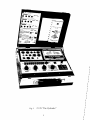
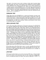
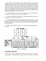
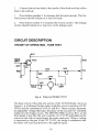
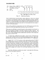
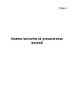
Fig. 1
TC28 "The Hybrider"
5
j
j
j
j
j
j
j
j
j
j
j
j
j
j
j
j
j
j
j
j
j
j
J
SETUP or "D" SWITCH: This rotary switch selects the control grid pin
for the emission test. It also serves as the shorts test switch, for any interelectrode shorts, by rotating the switch through its positions.
LIFE TEST: This slide switch provides a test of the useable life of a
tube by measuring how well the tube performs with a reduced filament
voltage.
CONTROLS RELATED TO TRANSISTOR TEST:
TEST SWITCHES: These six pushbutton switches apply the test voltage
to the elements of the device under test, and mechanically rotate lead
connection to all possible basing configurations, thus eliminating
requirements for basing or circuit infonnation.
CONNECTIONS: A socket panel provides a total of 13 tube sockets
plus 1 transistor socket for all test conditions. A test lead cable tenninated in 3 EZ Hook connectors facilitates in-circuit transistor or FET gain
and leakage tests.
OPERATION
TUBE TEST SET UP
Operation of the TC28 Hybrider has been designed for simplicity, speed
and accuracy. All that is necessary to completely check a tube is to
follow the basic test procedure outlined below.
1.
Connect the TC28 Hybrider to a grounded source of 105 to 125
volts, 50 to 60 Hz, AC power.
2.
Locate the tube type to be tested in the setup chart. Looking to the
right of the tube number, observe the setup information for the
controls labeled A,B,C,D and socket. Some tubes have more than
one listing indicating that the tube has more than one section to be
tested. Each section of the multiple tube is tested separately.
3.
Push the PIN ELIMINATION switches listed under A down to eliminate those pins. If none are listed, leave all switches in the up
position.
4.
Set the B,C, and D switches to the positions indicated and insert the
tube into the socket listed. Where more than one setting is listed,
make the emission and grid leakage test on each section. The shorts
test need be made only once.
SHORTS TEST
Set the TUBES/TRANSISTOR Function Switch to SHORTS and check
the front panel METER ZERO adjust to ensure a "0" indication on the
meter. Allow a period oftime for the tube filament to warm up, then
rotate the "D" switch slowly through all of its positions while observing
6
the meter. If no short exists or the resistance of the short is greater than
200,000 ohms, the meter will remain in the GOOD area of the GOOD/
BAD SHORTS scale. Shorts of 200,000 ohms or less will be indicated to
a relative degree on the SHORTS scale. Tubes having a directly heated
cathode (those in which the filament serves as the cathode) will show a
direct short between heater and cathode on the H-K position of the "D"
Switch. This is a normal condition and these tubes are indicated in the
setup book by an asterisk (*) .
EMISSION TEST
If the tube passes the SHORTS test, rotate the Function switch to the
EMISSION position and read the emission quality of the tube on the top
scale of the meter. A tube indicating in the questionable area (?), has
an emission level much lower than normal. It's replacement would be
determined by you and your customer, based on the nature of the circuit
in which the tube is to operate.
GRID-LEAKAGE TEST
If the tube reads in the GOOD area of the meter and passes the EMISSION
test, switch to GRID LEAKAGE and read the grid leakage of the tube on
the GRID LEAKAGE scale of the meter. This is a very important check
and will pinpoint troublesome tubes that may otherwise check good. If
the meter is indicating in the GOOD area of the scale but slowly rising,
wait a minute or so to allow the meter to stabilize before judging test
results. On large power tubes, such as a horizontal output tube, do not
make a grid leakage check after an extended emission check. If the tube
is left in the emission check position for several minutes, the grid will
heat up and, when switched to grid leakage, will read higher than normal.
Allow the tube to cool slightly before the grid leakage check. You can
expedite the grid leakage check by raising the filament voltage for a few
seconds. This is not the same overheating as was caused in the emission
check, but will show up grid leakage. If the grid leakage indication climbs
into the BAD area on the meter, reduce the filament voltage and see if the
meter remains in the bad area. If it does so, then the tube will give
trouble in the circuit and should be replaced. If the meter drops off
rapidly back into the GOOD area, then the tube is good.
If the tube passes all of the above tests, it can be considered good and
need not be replaced. If the tube is in the questionable area on any test,
it becomes a value judgement based upon circumstances as to whether or
not it should be replaced.
LIFE TEST
If the meter needle climbs very slowly into the GOOD area or Questionable
area of the meter on the Emission test, the life expectancy of the tube
can be considered much less than if the meter indicated GOOD in a
7
shorter period of time. Also, if the needle should climb into the GOOD
area and then "fall off," life expectancy can be considered much less.
A general measure of the usable life remaining in a tube can be obtained
by using the "Life test" position of the TC28 "Hybrider." Simply slide
the LIFE TEST switch to the right and hold it for a few moments. Observe
the emission level of the tube during this time. If the emission remains
the same or drops only slightly the tube can be considered good. If the
emission falls off quickly into the questionable or bad areas, it may be
wise to replace the tube. (The rapid drop in emission generally indicates a
short life expectancy).
FILAMENT WARM UP TIME
When replacing a costly horizontal output tube in a television receiver, it
is a good idea to not only check the horizontal oscillator for emission
and other standard tests, but to also check the length of time it takes to
warm up. If the horizontal oscillator tube is slower in warming up than
the output tube, the output tube will draw heavy current and its life will
be shortened considerably. Checking the warm up time of the oscillator
tube and making sure that it is as fast or faster than the output tube can
reduce the chance of a call back later for the same trouble and keep your
customer's confidence high in your service ability.
FILAMENT VOLTAGE SENSITIVITY
Some tubes may check good on the emission test and pass the other tests
in the Hybrider, but still not operate properly in the receiver. These tubes
may have a filament sensitive cathode. This means that the emission
from the tube will change with a change in the applied filament voltage to
the tube. This is caused from a low power line or defective power
transformer in the receiver. This type of tube can be most troublesome
in series string receivers. To test for this trouble, simply push the LIFE
TEST switch while monitoring the emission of the tube on the meter. A
good tube will not change its reading at all while a filament sensitive tube
will drop in emission. If the tube falls into the questionable area (?) on
the meter, it will give trouble in the circuit and should be replaced.
REJUVENATION
If you wish to rejuvenate a small tube, merely increase the filament
voltage by setting switch "B" one setting higher for ten to fifteen
seconds. This will super heat the cathode and boil out more emitting
material from under the oxide coating.
This is only a temporary
measure as rejuvenation of a receiving tube will not last very long.
8
SET UP FOR NEW TUBES
New tubes can sometimes be a problem as they may not be listed in the
set-up chart. This can be especially true on new receivers just introduced
by the set manufacturers. Though new tubes are seldom being added at
the present time, new tubes will undoubtedly appear in the future. With
an understanding of the setup controls and what each does, you can set
the Hybrider from a tube manual or even the schematic of the receiver
itself.
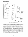
"A" PIN ELIMINATION
The "A" PIN ELIMINATION switch is used to isolate internal connections
of two pins to the same element of the tube so that a test may be made.
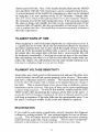
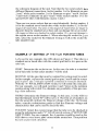
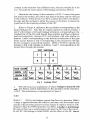
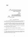
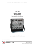
For example, the tube basing shown in Figure 2 is a 9QL basing. The control grid is tied to pins 2 and 6, the screen grid to pins 1 and 7 and pin 9 is
an internal connection that could be connected to any pin inside of the
tube. To eliminate any shorts indication other than that which are true
shorts in the tube, the PIN ELIMINATION switches 6, 7, and 9 would be
set in the down position to open these pins before the test is made. All the
numbers correspond to the tube base pin number except for socket
number 10, the compactron, where pin 11 is connected to PIN
ELIMINATION switch number 1. If no isolation is needed, all switches
should be in the uppermost position. After each tube is tested, push the
RESET switch to the right to place all switches in the up position. Each
can be moved independently of each other, either up or down or set with
RESET switch.
BASING 9QL
TERMINAL CONNECTIONS
pin 1 - Grid 112
Pin 7 - Grid M2
Pin 2 - Grid Itl
Pin 8 - Grid W3
Pin 3 - Cathode
Pin 9 - Internal connection
- do not U$e
Pin 4 - Heater
Pin 5 - Heater
Cop - Plate
Pin 6 - Grid Itl
BOTTOM VIEw
Fig. 2 9QL Basing for 6JE6 Tube
"B" FILAMENT
This switch selects the filament voltage applied to the tube under test
from 1 volt to over 50 volts. The twelve position switch selects a
voltage range and, with the unique design of the filament transformer,
9
the tube under test will load the transformer to obtain the correct voltage for testing.
When setting up a new tube, simply set the "B"
FILAMENT switch to the correct voltage or voltage range.
"C" LOAD
This switch selects the proper AC voltage to be applied to the plate of the
tube as well as the correct load resistor so that the tube's designed current
can be set and the tube checked under full load. The current ranges for
the settings of the "C" LOAD switch are as follows:
LOAD switch
Cathode Current
LOAD switch
Cathode Current
A
SOmA plus
20 - SOmA
15 - 30mA
10 -16mA
6 - l2mA
F
2 -7mA
.7 - 2mA
.5 - .SmA
.SmA or less
B
C
D
E
G
H
J
The current that the "e" LOAD switch is set to is the normal cathode
current under normal bias conditions as listed in the tube manual. If a
tube manual is not handy, compute the cathode current by the voltage
drop across the cathode or plate load resistor in the circuit or from the
schematic by using Ohm's Law.
"D" SET UP
The "D" switch is used to pick up the control grid for the test on the
tube. It was discovered many years ago that approximately 97% of the
electrons would go to the control grid when checking cathode emission.
This is now used as the pick-up element. In the example of Figure 2, the
"D" switch would be set to one of the control grids that is not isolated.
If pin 6 were to be isolated, the "D" switch would be set to pick up pin
2.
The only exception to the above is on socket number 10 where pin lion
the tube base is picked up with the first position of the "D" switch.
Sockets number 3 and 8 are wired identically except that socket number
8 has three pins not connected. This socket is used to isolate extra
connections where more than two base pins are connected to the same
element such as in the lX2 high voltage rectifier. The seven-pin sockets
4 and 7 are alike except that the filament pins on socket 4 are 3 and 4
while on socket 7 they are 1 and 7.
SOCKET SET UP
The sockets on the TC28 have the filament pins prewired to eliminate the
extra setup that is involved. The actual pin connections can be seen on
10
the schematic diagram of the unit. Note that the two octal sockets have
different filament connections. Socket number 1 is for filaments on pins
2 and 7 while socket number 2 is for filaments on pins 7 and 8. Sockets
3 and 8 have filaments on pins 4 and 5 while socket number 13 is for
special Hi-Fi tubes with filaments on pins 1 and 2.
There are two novar sockets that are wired identically. Socket number 5
is for the standard novar based tubes while socket number 12 is for the
magnoval based tubes. The pins on the magnoval based tubes are larger in
diameter than the standard novar base and can damage the novar socket.
All magnoval tubes are checked in socket number 12 to prevent damage to
the regular novar socket number 5. When selecting the socket for a new ,
tube, select the socket for the filament wiring as well as the socket the
tube should fit into.
4
EXAMPLE OF SETTING UP THE TC28 FOR NEW TUBES
Let's use for our example, the 6JE6 shown in Figure 2. This tube is a
standard novar based tube with the control grid tied to two pins on the
tube base.
FIRST: Determine the socket to use. In this case, the tube is a standard
novar base tube so that socket number 5 will be used.
SECOND: All the pins that must be isolated for testing must be noted.
In this example, we have the control grid on pins 2 and 6 and the screen
grid on pins 1 and 7 with pin 9 possibly connected to some pin internally.
With the "A" PIN ELIMINAnON switch,we will isolate the extra pins.
For our example, we will push switches 6 and 7 down to the isolation
position along with switch 9 to eliminate any possibility of this pin causing a false indication.
THIRD: Determine the filament voltage. In this case, it is the 6JE6 so
that the filament switch "B" will be set to 6. The first set of numbers on
the tube generally indicate the filament voltage of the tube. On foreign
tubes, consult a substitution guide to find the filament voltage and
characteristics that can be used to check the tube.
FOURTH: Select the current range that the tube is to be checked at
using the information under "C" LOAD switch section of "SETUP FOR
NEW TUBES. For our example, the A position would be used as the
6JE6 draws a very heavy plate current under normal use. Then perform
the tests as previously described.
11
TRANSISTOR TESTS
GAIN TEST
The gain test on a transistor or FET with the TC28 is actually simpler
than testing a tube. There is no need to know the transistor basing,
polarity, or even if it is a transistor or an FET. Merely connect the leads in
any combination and press the test buttons. Follow the procedure below
to make a gain test on a transistor or FET.
1.
Remove power from the equipment containing the device to be
tested and discharge all power supply filter capacitors.
Connect the TC28 to a source of 105 - 125 volts, 50 to 60Hz, AC
power.
2.
The test cable is located in the lead storage compartment. Connect
the test leads to the leads of the device to be tested. If the device to he
tested is a plug-in type and can be removed easily, you may use the transistor socket located on the socket panel in place of the test cable. It is
not necessary to determine basing of the device, the automatic test circuit
will accomplish this.
3.
Press each of the six test buttons in tum. If no audible chirp is heard
and meter does not indicate in the GOOD area of GAIN / EMISSION
meter scale, select the opposite polarity on the TUBES/TRANSISTORS
Function switch and press the six test buttons again. If audible chirp is
still not heard, the device being tested is bad. If the device tests bad in
circuit it should be removed from the circuit and retested before a replacement is installed. A good FET and most good transistors will give
a GOOD indication on two of the test buttons. If the exact basing of the
device under test is desired, refer to the section of this manual on
"Determining transistor basing." Some special devices such as Darlington
amplifiers or diode protected transistors will test good on only one test
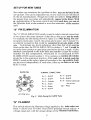
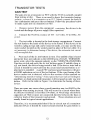
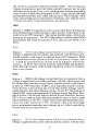
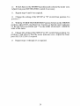
button. Refer to the table in Figure 3 to determine the basing of these
devices.
4.
There are some rare cases where a good transistor may test BAD by the
Hybrider when testing in-circuit. This will occur for a circuit whose base
to collector resistance is less than 100 ohms, or when large electrolytic
capacitors of 50uf or more are connected directly between the base or
collector leads of the transistor and ground. These situations are not
usually found in typical circuit applications.
Therefore, it is recommended that if the in-circuit test of a transistor
indicates BAD, it should be removed and retested for gain before a
12
replacement is installed. This retest should also include the out-of-circuit
leakage test.
If a transistor tests BAD in-circuit and GOOD out-of-circuit, this may
indicate other problems in the circuit. First check the schematic for
resistors of less than 100 ohms between base and collector or electrolytic
capacitors of SOuf or more connected to the transistor base or collector.
If these are not found, check the circuit board for the possibilities of:
1. Shorted foils on the board.
2. Large resistors, connected to the transistor, which may have changed
value or become shorted.
LEAKAGE TEST
It is possible for a transistor or FET to have good gain, and still not work
in the circuit because the leakage upsets the DC circuit values. The leakage test on a transistor is nearly the same as the grid leakage test of a
tube. To make the leakage test, proceed as follows:
1.
Remove the transistor from the circuit and plug it into the transistor
socket on the test panel or connect the test leads to the leads of the
device. Make the gain test and note which two test buttons result in a
good indication.
2.
Switch to the LEAKAGE test, and press the two buttons that gave a
good gain test. This test checks the ICBO and ICEO leakage values of
transistors and the IGDO and IGSO leakage of FET's. These leakages
should measure zero for FET's and small silicon transistors. High power
silicon and small germanium transistors may indicate up to 100uA
leakage, while germanium power transistors may indicate up to 3000uA
and still be acceptable.
3.
Press the remaining four buttons. Two of these will result in a full
scale leakage reading and the other two mayor may not indicate leakage
depending on the transistor. A junction FET will indicate full scale on
all four remaining buttons, while aMOS FET should indicate leakage on
only two buttons. If you desire to determine the exact type leakage for
a particular transistor, refer to the Locating Leakage section of this
manual.
DETERMINING BASING
If the device being tested checks good on two of the test buttons, it is
either a standard transistor or an FET. To determine if the device is a
transistor or FET, and the basing diagram, ifit is a transistor, it is
necessary to insert a resistor in series with the base/gate lead. The value
13
of this resistor will depend on the transistor being tested, but the
minimum value to use is 10K. If the device still tests good on two
buttons, the value of the resistor will have to be increased in 10% steps
(lOK, 12K, 15K, etc.) until it tests good on only one button. If the device
is still testing good on two buttons with a lOOK resistor in series with the
base, it is an FET. Since the source and drain are interchangeable on an
FET, it is not possible to determine the exact basing. To determine the
basing on a transistor, proceed as follows:
1.
With the transistor out of circuit, connect the TC28, and determine
which two test buttons produce a good indication.
2.
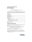
Refer to the table in Figure 3, to determine the base lead, and
connect a 10K resistor in series with it.
Retest the transistor and note which test button produces a good
indication. Increase the value of the base resistor as necessary until the
transistor tests good on only one button. Note the button that produces
a good indication.
3.
4.
Refer to the table in Figure 3, to determine the basing of the
transistor.
TEST SWITCHES
1
2
3
4
5
6
r - - - - - - TEST SWITCHES - - - - _ ,
ICBO
IBEO
IECO
lEBO
ICEO
(full scale)
3
2
1
LEAD COlOR
GREEN
E
S
B
G
C
YELLOW
8
G
C
D
E
RED
C
4
D
S
IBCO
(full scale)
6
5
C
D
B
G
E
8
G
E
S
C
S
0
B G
E S
C
0
8
G
TRANSISTOR OR FET BASING COMBINATIONS
0
E
S
Fig. 3 Lead Basing
LOCATING LEAKAGE
In some cases it may be desirable to determine the exact nature of leakage
in a transistor. With the test switches on the TC28 there is no need to
14
connect to the transistor four different ways, the test switches do it for
you. To locate the exact nature of the leakage, proceed as follows:
1.
Determine the basing of the transistor or FET. Connect the green
test lead to the emitter, the yellow test lead to the base and the red lead
to the collector. If the device is an FET, connect the yellow test lead to
the gate and the red lead to either the source or the drain. Connect the
green lead to the remaining element of the FET.
2.
Refer to Figure 4, and press the test button corresponding to the
desired leakage test. Note that for regular transistors, buttons number 2
and 6 will produce a full scale leakage indication, corresponding to the
conduction of the forward biased base-emitter and base-collector
junctions respectively, junction FET's will produce a full scale reading on
buttons 2 and 6 corresponding to the forward conduction of the gate
diode: and on buttons 3 and 5 corresponding to the current flow through
the low resistance source-drain channel. MaS or IG FET's should only
produce a full scale reading on buttons 3 and 5; corresponding to the
current flow through the channel.
TEST SWITCHES
1
2
3
4
5
6
TEST SWITCHES
I
LEAD COLOR
GREEN Els
YELLOW BIG
RED
clD
1
3
2
LZ7
'BEO
'GOO
'OSO
4
'EBO
~
i
5
6
Z L
ICEO
1000
Fig. 4 Leakage Chart
3.
The following is an explanation of which leakage is measured with
each test button, and its importance to the operation of the transistor
or FET. This information is summarized in Figure 5.
leBO
Button 1:
ICBO is the leakage current that flows in a transistor when a
voltage is applied between the collector and base, with the emitter open
and the collector-base junction reverse biased. (Collector positive with
respect to base for NPN transistor). Its effect is similar to grid leakage
in a tube in that even a small amount will upset the DC bias in the circuit.
In an FET, this leakage is called IGDO, and its effect on the DC bias of
15
1,
the circuit is even greater than for transistor ICBO. When making this
leakage measurement, press the button carefully and note any up scale
deflection of the meter. Even a very small up scale deflection should be
cause to reject a small silicon transistor or FET. Larger silicon and small
germanium transistors may safely indicate up to 50uA leakage, while
some special high power germanium transistors may indicate up to
3,OOOuA and still be within manufacturers specifications.
IBEO
Button 2: IBEO in transistors is the current that flows through the
forward biased base-emitter junction. (Base positive with respect to the
emitter for an NPN transistor). This button should produce a full scale
indication for transistors. For FET's this leakage would be called ISGO
and indicate full scale for junction FET's and zero for MOS or IG
FET's.
IECO
Button 3:
IECO is the leakage current that flows in a transistor when a
voltage is applied between emitter and collector with the base open.
(Emitter positive with respect to collector for an NPN transistor). IECO
is a measurement of the transistors ability to block reverse voltages, such
as would be encountered in circuits with an inductive load in the
collector. In FET's, this current would be called lDSO and should indicate full scale because of the normal conduction of the low resistance
drain source channel.
lEBO
Button 4:
lEBO is the leakage current that flows in transistors when a
voltage is applied between emitter and base, with the collector open and
the emitter-base junction reverse biased. (Emitter positive with respect
to base for NPN transistor). lEBO is most important in pulse circuits,
where the base is driven deep into reverse bias and the leakage current
could influence the pulse shaping circuits. In an FET, this leakage is
called IGSO, and is a measurement of leakage current that flows from
gate to source, with the gate source junction reverse biased for junction
FET's. Even a small up scale deflection should be cause to reject a small
silicon transistor or any FET. Larger silicon and small germanium transistors may safely indicate up to 50uA of leakage, while some special high
power germanium transistors may indicate up to 3,OOOuA and still be
within manufacturers specifications.
ICEO
Button 5:
ICEO is the leakage current that flows in a transistor when a
voltage is applied between the collector and the emitter, with the base
16
open. (Collector positive with respect to emitter for an NPN transistor).
Excessive ICEO will cause a transistor to operate unreliably in any circuit,
however, the transistors most prone to this type leakage are high power
types such as those used in audio output circuits and power supply
regulators. In FET's this current would be called ISDO and should
indicate full scale because of the normal conduction of the low resistance
source-drain channel.
IBCO
Button 6:
IBCO in transistors (Base positive with respect to the
collector for an NPN transistor) is the current that flows through the
forward biased base-collector junction. This button should produce a full
scale indication for transistors. For FET's this leakage would be called
IDGO, and indicate full scale for junction FET's and zero for MOS or
IG FET's.
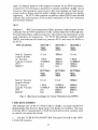
TYPE OF DEVICE
Small Si. Transistor
Large Si. & Small
Ge. Transistor
Large Ge. Transistor
JFET
MOSFET
Small Si. Transistor
Large Si. & Small
Ge. Transistor
Large Ge. Transistor
JFET
MOSFET
BUTTON 1
ICBO
(GOO)
BUTTON 2
IBEO
(SGO)
'ECO
(OSO)
O-.1uA
3000uA
O·.1uA
1-50uA
10-3000uA
OuA
OuA
3000uA
3000uA
3000uA
OuA
1-50uA
10·3000uA
3000uA
3000uA
BUTTON 4
lEBO
(GSO)
BUTTON 5
'CEO
(SOO)
BUTTON 6
IBCO
(OGO)
0-.1uA
0-1 uA
3000uA
1-50uA
10-3000uA
OuA
OuA
10·500uA
100-3000uA
3000uA
3000uA
3000uA
3000uA
3000uA
OuA
BUTTON 3
Fig. 5 Maximum Leakages for Good Transistors and FET's
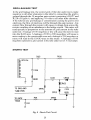
CHECKING DIODES
The leakage test on the TC28 provides a simple, accurate method of
determining the front to back ratio of a diode or rectifier. The test
switches allow measurement of both forward and reverse currents with
no need to reconnect the diode.
1.
Set the TUBES/TRANSISTORS Function Switch to the NPN
LEAKAGE position.
17
Connect the red test lead to the anode of the diode and the yellow
lead to the cathode.
2.
3.
Press button number 1 to measure the forward current. The forward current should indicate at or near full scale.
4.
Press button number 6 to measure the reverse current. The leakage
current should indicate at or near zero on the leakage scale.
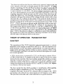
CIRCUIT DESCRIPTION
THEORY OF OPERATION - TUBE TEST
8.2V
SIGNAl..
NPUT
TRI03
RI36
RI27
R128
...----e
RI32
RI30
---JV\A,..----e-...JVV'v-..----~< RIO
RI29
eRial
SW4F
SW4G
Fig. 6 Tube-test Bridge Circuit
The basic circuit of the tube-test section of the TC28 Hybrider, shown in
Figure 6, is a balanced bridge meter amplifier circuit consisting of FET
TRI03 and the combination ofRI36 and RIO. These resistors represent
an adjustable voltage that takes the place of the second FET normally
needed for the bridge circuit. The METER ZERO control, RIO, on the
front panel is just like the zero controls of a VTVM and balances the
circuit so that with no signal input, the meter reads zero. When a voltage
is impressed on the gate of the FET TRI03, the bridge is unbalanced and
the meter will read in proportion to the applied signal.
18
EMISSION TEST
R2
R3
A
RI03
SW3
B
CliO
-R4
SW4D
R5
RI31
H
J
TRI03
CII2
1--
R6
G
TO GATE
R7
SW4E
R8
TO SW5 8
CATHODE
OF TUBE
R9
SW4C
TO SW5 8
GRID OF TUBE
Fig. 7 Emission Test Circuit
The cathode emission test puts AC voltage between the control grid of
the tube under test and the cathode, with a load resistor in series with the
cathode to develop a pulsating DC voltage. The "C" LOAD switch selects
the different size load resistors and applied voltage so that a full range of
current is available from less than .5mA to l20mA. The tube under test
rectifies the applied AC voltage and develops a voltage drop across the
load resistors R3 through R9. The pulsating DC voltage is coupled
through the filter network ofRI03 and ClIO to smooth it to a pure
DC voltage. This voltage is applied to the gate of TRI 03 through an
additional isolation and filtering network ofR127, R128, R13l, and
C 112, shown in Figure 6. The resultant DC voltage is coupled through
SW4D and upsets the balance of the circuit causing the meter to read upscale in proportion to the emission quality of the tube.
19
GRID-LEAKAGE TEST
In the grid leakage test, the control grid of the tube under test is made
negative to all other elements in the tube by connecting the grid to
ground through the 30 megohm gate resistor consisting ofRl27 and
R128 of Figure 6, and applying +8 volts to all other tube elements.
If the tube has any grid leakage or contamination causing the grid to emit
electrons, the flow of electrons will be through the gate resistor. Any
current flow through the resistor will cause a voltage drop across the
resistor resulting in an unbalance in the bridge circuit. The meter will
read upscale in proportion to the amount of grid current in the tube
under test. A leakage of 100 megohms or less will cause the meter to read
into the BAD area. A leakage of 100 to 200 megohms will cause a
meter reading in the questionable area and a leakage of 200 megohms or
more will read in the GOOD area on the meter. A leakage of 100
megohms represents a grid current in the tube under test of. 5 microamps.
SHORTS TEST
RI02
CI05
CI06
CI08
SW4E
CRI02
-TO SW5 AND
TUBE PINS
TO GATE
TRI03
SW4C
CRIll
R'31
..
SW4D
•
..IV\/'
fCII2
--
j
--
Fig. 8 Shorts Test Circuit
20
The shorts test utilizes the Sencore stethoscopic approach where each and
every element in the tube is checked against all other elements. A voltage
divider consisting of C 105 and Rl02 in figure 8 is placed across the 40
volt secondary of the transformer. The 40 volts AC RMS is divided down
to approximately 34 volts RMS. The lower voltage is necessary to prevent
arc over and breakdown in nuvistors and frame-grid tubes. CI06 is a
coupling capacitor which prevents any DC action of the tube from upsetting the shorts test. Any shorting resistance present between the tube
elements will upset the action of the voltage divider which will in tum
increase the AC voltage at the input of the peak-to-peak detector
comprised of CR102 and CR103. The output of the peak-to-peak
detector is filtered by C 108 and C 109 and presented across CRIll and
Rl05. CRIll prevents an upscale meter indication with no short present at the tube elements by blocking DC voltages of less than 0.6 volts.
The output of the detector greater than 0.6 volts DC is applied to the gate
of TRl03 through SW4D. The increased DC level at the source ofTRl03
causes the meter to indicate up scale in proportion to the severity of the
short. R105 at the detector output is a calibration control that establishes
the sensitivity of the test such that a shorting resistance of less than
200,000 ohms will indicate BAD on the meter.
THEORY OF OPERATION - TRANSISTOR TEST
GAIN TEST
The operation of the TC28 transistor gain test represents a unique
approach to the testing of transistors and FET's. The test depends on a
good transistor or FET providing a signal polarity reversal from input to
output when operating with the emitter or source common. Refer to the
TC28 Schematic and Parts List insert for this brief description of overall
test circuit operation.
A 2KHz square wave is generated by IC lB, and through an emitter follower TRIO 1 and TRI04, is coupled to the base or gate of the device under
test by the test switches. The test switches ground the emitter or source
and also connect a positive 5 volts from the power supply to the
collector or drain. If the device under test is good, the collector signal
voltage developed at the junction of RIll and Rl12 will be 180 degrees
out of phase with the base signal.
The base signal from the 2KHz oscillator is amplified by ICIC,and the
I collector signal is amplified by ICID. The outputs ofICIC and
coupled to the logic circuit of IC2, that provides an output to the meter
and speaker only when the two input signals are 180 degrees out of phase.
This provides both audio and visual indication of a good transistor.
21
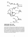
POWER SUPPLY
+
RI38
150
5W
CRIIO
5.1V
CII3
100uf
-,
ICI
rI
I
-RI37
8.2V
330
CI/5
OI
r·-
+
CRI06
8.2V
-
d
CRI07
.5v
-::CRI09
I4VAC
FROM TRANSFORWER
of CII6
2
00.t
+ CII7
14
I
CII4
100uf
CRI08
5.1V
-,
IC2 I
•POWER I
I
•
L-1-J
_oJ
7
14
I
POWER,
L _
r-
I
•
-
200uf
RI39
150
5W
Fig. 9 Power Supply Schematic
The 14VAC from the transformer is rectified by CRI07 and CRI09,
shown in Figure 9, and filtered by CII6 and CII7 to produce 16 volts DC.
This voltage is regulated by RI37 and CRI06 to produce 8.2 volts DC for
the bridge circuit. Positive and negative 5 volts DC for transistor test voltages are obtained from CRIIO, CRI08, and RI38. The plus 5 volt supply
is filtered by CII3, and the minus 5 volt supply is filtered by CII4.
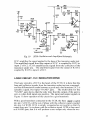
2KHz OSCILLATOR AND SIGNAL AMPLIFIERS
IC IB is connected as a square wave oscillator operating at approximately
2KHz as shown in figure 10. The frequency of operation is determined
by RI08 and CIa 1. The amplitude of the output signal is set by the ratio
ofRI06 and RI07. TRIal and TRI04 operate as dual emitter followers
providing a low impedance source for the 2KHz signal. TRIal and
TRI04 are both biased off and have a common emitter load resistor
RII8. TRIal passes the positive portion of the square wave and TRI04
passes the negative portion. The total square wave signal then appears
across RII8.
The 2KHz signal is coupled by RII9, SW4H, and the test switches to the
base of the transistor under test. It is also coupled to the non-inverting
input ofICIC by CI04 and RI20.
22
Rill
RII2
-5V
lCIOI
.01
Rloe
33K
RI06
RII5
2.4M
5°/.
RIIO
3.9K
1M
RI09
1M
2
+5V
ICIB
LM3900
10
R125
TRIOI
2N5l72
Rl21
.01
330K
,.............-..---4
RII6
3.3K
IK
CI04 RI20
22K
Rile
ICIC
LM3900
IK
TRI04
2N5227 I5V
TO BASE
RI/9
OF
220
TRANSISTOR
9
RI22
330K
R123
IK
Fig. 102KHz Oscillator and Amplifiers Schematic
IC 1C amplifies the signal applied to the base of the transistor under test.
The amplified signal from the output of IC 1C is coupled by R123 to
input 2 oflC2. ICID amplifies the signal from the collector of the
transistor under test. The amplified signal from the output oflCID is
coupled by Rl25 to input 4 oflC2.
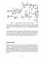
LOGIC CIRCUIT AND INDICATOR DRIVE
The logic circuitry oflC2 is the heart of the TC28. It is here that the
base and collector signals from the transistor under test are compared,
and the differentiation made between a good and a bad transistor. IC2 is
actually a quad, two-input "NAND" gate.
The truth table for the
"NAND" gate shows that the only time that the output of the gate is
zero is when both inputs are positive. The input and output signals in
Figure 11 show operation of the circuit for a good transistor.
With a good transistor connected to the TC28, the base signal coupled
into pin 2 of IC2A will be out of phase with the collector signal coupled
into pin 4 of IC2B. IC2A is simply connected as an inverter so that it's
output from pin 3 is in phase with the collector signal. IC2B is then used
as a NAND gate, that is it will produce a zero output only when the two
23
1J1J
II RI24
CRII3
CRII2
CIII SW4G
IC2C
FROM
RII7
.1
RI23
ICIC
RI33
IC28
CRIOI
FROM
RI25
RI26
ICID
CRI05
SW4F
Fig. 11
Logic Circuit and Indicator Drive Schematic
-
inputs are positive. Finally, IC2C is used as an inverter so that it's output
is positive only when the input pin 12 is zero. This pulsating positive
output from IC2C is used to drive the meter and the speaker transistor
TRl02.
A bad transistor will not yield an out-of-phase collector signal for pin 4
input ofIC2B. IClD is biased such that it's output is zero when there is
no input signal from the collector of the transistor under test. This zero
level is coupled to pin 4 ofIC2B and makes the output at pin 6 positive.
The output of IC2C is then zero which indicates BAD on the meter.
LEAKAGE TEST
The collector lead of the transistor under test is connected through RIll
and Rl12 to plus or minus 5 volts by one section of SW4B, as shown in
Figure 12. The base lead of the transistor under test is connected to
ground through Ml by SW4F or SW4G and indicates the leakage
current through the transistor. CR10 1 provides meter compression and
RlOl is a calibration adjustment to set the full scale leakage sensitivity at
3000uA. The emitter lead is disconnected from the circuit by one section
ofSW4J.
24
+5V
-5V
";W48
RII2
Rill
VV\;--IV\A-----
TO
•
COLLECTOR
TO
BASE
CRIOI
MI + RIOI
SW4G
•
l-
NC ' ".
T_O
_
EMITTER
Ne. SW4J
Fig. 12
Lea/wge Test Circuit
SERVICING THE TC28
DISSASSEMBLY INSTRUCTIONS
To remove the TC28 from its case for adjustment of the internal calibration controls, or to facilitate service, merely remove the four screws
from the back of the instrument case. The front panel may now be lifted
from the case, exposing all circuitry for calibration or service. All of the
circuitry, except for the point-to-point wired switches and sockets, has
been contained on the one printed circuit board. The board may be
easily removed by simply unplugging the keyed molex connectors and
removing the two screws that hold the board in place. To re-assemble the
TC28 merely reverse the above procedure.
25
CALIBRATION
CRI
Rl
R2
R3
= Silicon Diode,
= 100 Meg (4-22
lOOPIV @ .5AMP
MEG and
CRI
1-12 MEG in series)
= 270K
= lK, 1%
RI
R2
R3
OLD TUBE BASE OR OCTAL PLUG
Fig. 13
Calibration Module
The TC28 Hybrider should seldom need calibration. However, should
you desire to periodically check the TC28 calibration accuracy, thereby
insuring its top performance, the calibration module described above in
Figure 13, is recommended. The module can be constructed on an octal
plug or discarded octal tube base and is to be inserted into the socket 1
on the TC28 socket panel.
Some of the calibration adjustments for the TC28 interact and for this
reason the following adjustment procedure must be followed:
There are six calibration controls located on the printed-circuit board in
the TC28. Refer to Figure 14 for the location of these controls. The
first three adjustments have to do only with the tube test functions of
the TC28. The remaining three adjustments pertain to the transistor
test portion of the TC28.
1.
To begin the calibration procedure, remove the TC28 from its
cabinet and, with the unit in its normal operating position, adjust the
mechanical-zero adjust on the meter of the TC28 for a "0" indication.
2.
Apply 105 - 125 VAC power to the unit and turn the TUBES/
TRANSISTORS Function Switch to the NPN LEAKAGE position.
Connect the positive terminal of a DC milliameter to the red test lead.
Connect a 2000 ohm variable resistor between the negative terminal of
the meter and the yellow test lead. Press TEST button No.1 and adjust
the external resistor until the external meter indicates 3. OmA. Adjust
RIal, the Leakage Cal. Control, for a full scale indication on the TC28
meter.
Insert the calibration module into socket 1 and make the following
setup on the front panel selectors:
3.
A
B
c
ALL UP
I
D
D
4
26
SKT
SENCORE
·43A65
RIOI
~I""~
22M2.
5 4T
flY IVW
2W
• 2& 24 Z3 •
81. II IlL V
17
•
RI32
I
Fig. 14
I
I
Circuit Board Layout
4.
Set the TUBES/TRANSISTORS Function Switch to SHORTS and
adjust the meter to zero with the front panel METER ZERO control.
5.
Switch to the GRID-LEAKAGE position on the Function switch
and adjust R132, the Grid Leakage Cal. Control until the meter reads
between the "?" and BAD on the GRID LEAKAGE scale on the meter.
6.
Switch back to SHORTS and recheck the meter zero. Adjust front
panel METER ZERO control if necessary.
7.
Repeat steps 4 and 5 as required to achieve continuity.
8.
Change the setting of the SETUP or "D" switch from position 4 to
position 3.
9.
Set the TUBES/TRANSISTORS Function Switch to EMISSION and
adjust RI03, the Emission Cal. Control until the meter indicates "?"on
the EMISSION/GAIN scale of the meter.
27
10. Switch back to the SHORTS position and recheck the meter zero.
Adjust front panel METER ZERO control if necessary.
11.
Repeat steps 9 and 10 as required.
12. Change the setting of the SETUP or "D" switch from position 3 to
position 5.
13. With the TUBES/TRANSISTORS Function Switch in the SHORTS
position, adjust R105, the Short Cal. Control, so that the meter indicates
on the line between GOOD and "?"on the GRID LEAKAGE - SHORTS
scale of the meter.
14. Change the setting of the SETUP or "D" switch from position 5 to
position 7 and observe that the meter indicates zero. Adjust the front
panel METER ZERO if required.
15.
Repeat steps 11 through 13 as required.
28
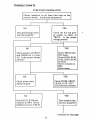
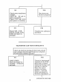
TROUBLE CHARTS
TUBE TESTS INOPERATIVE
Checks operation on all three tube tests on the
function switch. Are all tests inoperative?
I
NO
YES
Check the 8.2 volt power supply on drain of
TRI03. Is the proper
voltage present?
Does grid leakage check
function properly?
NO
YES
Check TRI03 with
FET tester.
Check R129, R130,
R132, R133, R136,
and RIO.
Check contacts on
SW4.
Check meter.
Check junction of CRI07
and CRI09 for 14 volts
AC. Is the proper voltage
present'?
I
NO
YES
Check CRI06, CRI07,
CRI09, CI15 - ClI7
and replace as necessary
Check power transformer outputs
NO
YES
Check R127, R128 and
contacts on SW4. Check
calibration action of R132.
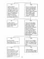
Does emission test
function properly?
continued on next page
29
II
I
NO
YES
Check power transformer
voltages.
Check R2 - R9 and replace as necessary.
Check ClIO and RI03
and replace as necessary.
Does shorts test
function properly?
I
NO
YES
Check CI05 - CI09,
CRI02, CRI03, RI04,
RI05 and replace as
necessary.
Complete the calibration
procedure.
TRANSISTOR GAIN TEST INOPERATIVE
Check test leads by shorting all three leads, switching to leakage and pressing all 6 buttons in sequence.
Do all buttons indicate full scale?
I
I
YES
NO
Connect a known good
transistor to the TC28:
green lead to emitter,
yellow lead to base, and
red lead to collector.
Select the correct
polarity, and press
button 1. Are both
meter and speaker indications inoperative?
CONCLUSION:
Check and replace as
necessary: wiring and
test leads.
I
continued on next page
30
I
I
NO
YES
CONCLUSION:
Check for plus 4 volts
at pin 11 of IC2 and 4
volt 2KHz pulses at pin
12 with button 1 pushed. If both signals are
present, troubleshoot
defective indicator
circuit. If one signal
is missing, replace IC2.
Remove transistor and
connect scope ground
lead to green test lead,
press button 1, and
measure signal on yellow
and red leads. Does
yellow lead measure
3 vp-p and red lead
measure ..±. 5 volts?
I
YES
NO
Connect known good
transistor to the TC28:
green lead to emitter,
yellow lead to base,
and red lead to collector.
Select the correct
polarity, press button 1,
and using a dual trace
scope, check for out of
phase signals on inputs 3
and 8 of ICI. Are proper
signals present?
CONCLUSION:
Start at baseofTRl0l,
locate where 2KHz
signal is lost.
I
YES
NO
Check for out of phase
signals at inputs 2 and 4
of IC2. Do signals swing
from -.5 volts to 4 volts
DC?
CONCLUSION:
Use scope to locate where
2KHz signal is lost.
r
I
YES
NO
CONCLUSION:
If power supply voltages
are normal, replace IC2.
CONCLUSION:
Trace signal back to output pins 9 and 4 of ICI.
If no output at pins 9
and 4, and power supply
connections are good,
replace ICI.
31
SERVICE AND WARRANTY
You have just purchased the finest amplifier tester on the market today.
The Sencore TC28 has been inspected and tested twice at the factory and
has passed a rugged use test by our Quality Assurance Department to
insure the best quality instrument to you. If something should happen,
the TC28 is covered by a standard 90 day warranty as explained on the
warranty policy enclosed with your instrument.
Sencore has six regional offices to serve you. Instruments to be serviced
should be returned to the nearest regional office by UPS if possible.
Parcel post should only be used as a last resort. Instruments should be
packed with the original packing materials or equivalent, and double
boxed to insure safe arrival at the regional office. The display carton IS
NOT an acceptable shipping container. When returning an instrument
for service, be sure to state the nature of the problem to insure faster
service.
If you wish to repair your own TC28 Hybrider, we have included a
schematic, trouble charts, and parts list. Any of these parts may be
ordered directly from the regional office nearest you.
We reserve the right to examine defective components before an in
warranty replacement is issued.
SENCORE REGIONAL OFFICES:
East Central Sales & Service
4105 Duke Street
Alexandria, VA 22304
AIC 703-751-3556
TWX 710-832-0618
Central Sales & Service
2711 B. Curtis Street
Downers Grove, IL 60515
AlC 312-852-6800
TWX 910-695-3226
Western Sales & Service
833 Mahler Rd.
Burlingame, CA 94010
A/C 415-697-5854
TWX 910-375-3307
Central West Sales & Service
3200 Sencore Drive
Sioux Falls, SD 57107
A/C 605-339-0100
TWX 910-660-0300
Southeastern Sales & Service
2459 Roosevelt Hwy., Suite B9
College Park, GA 30337
AlC 404-768-0606
TWX 810-751-3546
Northeastern Sales Office
1593 H Central Avenue
Albany, NY 12205
AlC 518-869-0996
TWX 710-444-4969
32
Page 32: "Sencore Regional Offices"
The Northeastern Sales Office address has been changed to:
1237 Central Avenue
Albany, New York 12205
(518) 459-6040
The Southeastern Sales Office address has been changed to:
2459 Roosevelt Hwy., Suite B3
College Park, Georgia 30337
(404) 768-0606
ADDITIONAL APPLICATION NOTES
IN-CIRCUIT TESTING
There are some rare cases where a good transistor may test BAD by
the Hybrider when testing in-circuit. This will occur for a circuit
where the base to collector resistance is less than 100 ohms, or when
large electrolytic capacitors of 50mF or more are connected directly
between the base or collector leads of the transistor and ground.
Therefore, it is recommended that if the in-circuit test of a transistor
indicates BAD, it should be removed and retested for gain before a
replacement is installed. This retest should also include the out-ofcircuit leakage test.
If a transistor tests BAD in-circuit and GOOD out-of-circuit, this
may indicate other problems in the circuit. First, check the schematic
for resistors of less than 100 ohms or electrolytic capacitors of 50mF
or more, connected between the transistor base and collector. If
these are not found, check the circuit board for the possibilities of:
Shorted foils on the board, or resistors or capacitors connected to
the transistor which may have changed value or become shorted.
"GOOD" READING ON ONLY ONE BUTTON
All good FET's and most good transistors will show a GOOD gain
reading when either of two buttons is depressed. However, there are
a few transistors, such as Darlington pairs, or devices with protective
diodes between emitter and collector, that will read good on only
one button.
If an in-circuit transistor shows GOOD gain on only one button, it
may indicate a leakage condition. Therefore, it is recommended that
such a transistor be removed from the circuit and tested again, both
for gain and leakage. If the transistor gives a GOOD reading on only
one button and does not show excessive leakage when tested out of
circuit, the transistor is good and is probably one of these special
types.
Form 1281
TC28 MANUAL ADDENDUM
Please note these changes to the TC28 Hybrider manual (Form 959).
Mark the following sections in the manual "Revised - Refer to
Addendum," and use these instructions.
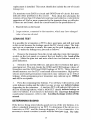
Page 13: "Determining Basing"
If the device being tested checks good on two of the test buttons, it
is either a standard transistor or an FET. To determine if the device
is a transistor or FET, and the basing diagram, it is necessary to
insert a lOOK ohm variable resistor in series with the base/gate lead.
Perform the Gain Test with the control at zero ohms and increase
the resistance in 10% steps. Retest both buttons at each step until
the device tests good on only one button. This indicates the device
is a transistor. If the device still tests good on two buttons with the
total lOOK resistance in series with the base/gate lead, it is an FET.
Since the source and drain are interchangeable on an FET, it is not
possible to determine the exact basing. To determine the basing on a
transistor, proceed as follows:
1. With the transistor out of circuit, connect the TC28, and determine
which two test buttons produce a good indication.
2. Refer to the table in Figure 3 to determine the base lead, and
connect a lOOK ohm control in series with it.
3. Retest the transistor and note which test button produces a good
indication. Increase the resistance of the control as necessary
until the transistor tests good on only one button. Note the
button that produces the good indication.
4. Refer to the table in Figure 3 to determine the basing of the
transistor.
TEST SWITCHES
1
2
3
4
5
6
r - - - - - - - TEST SWITCHES - - - - - - ,
leBO
IBEO
(full scale)
J
2
LEAD COlOR
GREEN
YELLOW
RED
'Eeo
3
E
S
B
G
B
G
C
0
C
E
'EBO
'eEO
4
5
IBCO
(full scale)
6
0
C
0
B
G
0
C
E
S
B
G
E
S
S
B
G
E
S
E
C
S
0
C
0
B G
TRANSISTOR OR FET BASING COMBINATIONS
Fig:J
fA'ad Hasin/I
S=NCO~=
3200 SENCORE DRIVE, SIOUX FALLS, SOUTH DAKOTA 57107
Tees
TUBE & TRANSISTOR TESTER
SCHEMATIC AND PARTS LIST
SE::NCOI tE
THE ALL AMERICAN LINE OF HIGH QUALITY TEST EQUIPMENT
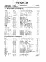
TC28 PARTS LIST
SCHEMATIC
REFERENCE
PART
NUMBER
DESCRIPTION
PRICE
P.C. BOARD MOUNTED COMPONENTS
ICIOI
ICI02
TRI0l, 102
TRI03
TRI04
CRI0l, 104, 105
111-114
CRI02, 103
CRI06
CRI07, 109
CRI08, 110
RI0l
RI03
RI05
R132
R138, 139
C 101-104,
110, 112, 115
CI06, 108, 111
CI09
C113,114
C116, 117
69G9
69GI0
19A28
19C11-1
19A16-1
IC, Quad Op Amp, LM3900
IC,Quad Nand Gate, SN7400
Transistor, NPN, 2N5172
FET, N-channel, 2N5457
Transistor, PNP, 2N5227
2.50
1.25
.50
1.75
.75
5005-2
50C3-1
50C4-2
16S10
50C4-13
15C7-2
15C7-8
15C7-6
15C7-2
14B49-9
Diode, IN4148
Diode, IN34A
Diode, Zener, 8.2V
Rectifier, 0.5A, 400 PIV
Diode, Zener, 5.1 V
Control, 10K, Leakage Cal
Control, I.2M, Emission Cal
Control, 500K, Shorts Cal
Control, 10K, Grid Leak Cal
Resistor, 150 Ohm, 5W, 10%
.25
.25
.75
.50
1.00
.75
.75
.75
.75
.25
24G126
24G293
24G289
24G118
24G181
Capacitor, 0.01 mF
Capacitor, O.lmF, Mylar
Capacitor, 0.47 mF, Mylar
Capacitor, 100mF, Lytic
Capacitor, 200mF, Lytic
.50
.50
.75
.50
1.00
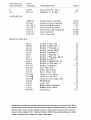
CHASSIS MOUNTED COMPONENTS
RIO
R2,3
Cl
C2
C3
Tl
SWI
SW2
SW3
SW4
SW5
SW6-15
SW16
SWI7, 18, 19
20,21,22
Ml
15CI-38
14B49-9
24G120
24G140
24G25
28B58D
25G197
25A154
25A157
25A196
25A158
25A155
25A156
1.25
Control, 200 Ohm, Meter Zero
Resistor, 150 Ohm, 5W, 10%
.25
Capacitor, 1OmF, Lytic
.25
.25
Capacitor, .002mF
Capacitor, 220pF, Disc
.25
15.25
Transformer, Power & Filament
Switch, Slide, LIFE TEST
1.00
Switch, Rotary, FILAMENT
4.50
Switch, Rotary, LOAD
3.25
Switch, Rotary, FUNCTION
7.25
Switch, Rotary, SELECTOR
3.50
Switch, Slide, PIN ELIMINATION 2.75
.75
Switch, Slide, RESET
25A186
23C51
Switch, PUSH Push
Meter, 6", 100uA
3.50
22.75
SCHEMATIC
REFERENCE
PART
NUMBER
DESCRIPTION
II
20Gl2
48A2-2
Neon Bulb, No. NE-2
Speaker, 2", 8 ohm
108B107
l43A65
l43A58-.l
l43A58-2
l68Gl2
llOC3ll
llOC313
Socket Panel Assembly
Printed Circuit Assembly
Push Switch Assembly
Push Switch Assembly
Hook and Cable Assembly
Case Assembly
Cover Assembly
LSI
PRICE
.25
2.75
ASSEMBLIES
24.50
42.25
7.25
7.25
10.00
25.00
15.25
MISCELLANEOUS
26G4
26G65
26G63
26G56
26G23
26G2
2603
26G15
26G2l
26G54
26G183
26Gl05
2lA32
2lA33
2lA44B
21A44R
21A59R
21A58
27Gl4
37A16
37A26
8Bl09B
Socket, Octal, 1&2
Socket, 10 Pin min., 3
Socket, 7 Pin min., 4
Socket, Novar, 5&12
Socket, Nuvistor, 6
Socket, 7 Pin min., 7
Socket, 9 Pin min., 8&13
Socket, Loctal, 9
Socket, Compactron, 10
Socket, 10 Pin min., 11
Socket, Transistor
Clip, Plate Cap
Knob, Bar Pointer
Knob, Meter Zero
Glamour Cap, Black
Glamour Cap, Red
Glamour Cap, Large, Red
Pushbutton
Line Cord
Rubber Foot, Bottom
Rubber Foot, Back
Escutcheon
.50
.50
.25
.50
.50
.25
.25
3.25
.50
.50
1.25
.75
.75
.75
.25
.25
.25
.25
2.25
.25
.25
3.25
Components not listed are standard replacement parts and may be purchased locally. When
ordering parts, please specify instrument model number, schematic reference, part number
and description. Please include remittance (check or money order) with your order, otherwise
invoices will be shipped C.O.D.
Minimum billing is $3.00. Prices and specifications in effect
at date of printing and are subject to change without notice.
NOTES
lALL CAPllCITANCES GREATER THAN ONE ARE pl.
~S~EJ~S O::~O:~
tta:
!i' ~~fis O~~~~~I~E
2
NOTED
3. DASHED LINES (----) REPRESENT MECHANICAL
PARTS AND CONNECTIONS
4. FUNCTION SWITCH SHOWN IN OFF POSITION.
5.ALL FILAMENT CIRCUIT VOLTAGES MEASURED
WITH RESPECT TO GREEN LEAD OF TI . ALL
OTHER VOLTAGES MEASURED WITH RESPECT
TO CIRCUIT GROUND WITH 15 MEGOHM INPUT
DIGITAL MULTIMETER
6.FRONT PANEL CONTROL NAMES ARE ENCLOSED
IN A BOX. c=::=:::::J
Z PC BOARD CONNECTIONS CORRESPOND TO
SCHEMATIC REFERENCE NUMBERS
2KHz OSCILLATOR
'--;1----_~..--------,2M
8= '
0"'"
r------'-·+--..::·:..:,..,<·)-----:;:;"""-f;;.."*~~..
T.
~':
,.
8IW
[ 1---=-=:<,.:>--------------,
BASE
2"'22.7
..
-5\1
..
:':.
r---------~
~
l
EMISSION CAl....
Rl03
'2M,""
1
..'~1i"
~
"'""
.....
CIOO
",
1M4l48
SOOI(
""IT,
.....
-
E
I
IClCMC
~.
1CIO..
i
'1
..
PC BOARD
43A58-2
SW2OI'Wt!+-
II
'T.
INDICATOR
METER
BRIDGE
~
~~.
LOGIC CIRCUIT
~~21(15. ;1!H
";b'.O.O.
__ ..
~ t,V
DRIVE
!FILAMeNTI
I
+
COIIO
i"',tv
0131
100II
<113
I
11
10""
I
~_l'<_,
r _
- --r'
~
•
>--
'
,
.
s6~tT
-0
y
.""
f-ff-
M.,
_."
,
I I{
lli
l
I leo I
.ICIOZ I
1~IIPOW'ERI
~ -
u .....c
\' \' \'
LMDOO
I I:::~,:,:~~. :; '~~=' .•
+t~l?f. t"fc,'"
......: m ,.
&
I
•
'I
~'.
-="
_
SHORTS TEST
l{
lli_
I
i
OUTPt~ :-~=
:.
Tltl04
~...L.~
...
""1 •...1 ....1
=-"~:.~~'=
.,. ~~72'":. ~tlFIERS,~ ~
~
eM>
43A5B-1
PC BOARD
COLL£CTOR IN
...
~
~EST
LEADS
\' \' \'
PIN CONNECTtONS
1Ic..=':'---"=i ~
PC. BOARD
43A65-D
~
~
~
~
c...:.
~1"1,.~
lI.
~"
T
~'W'"
1~:;~"'::1.lTIONS
SW48
(SW4J
iLv
'-
'q:
,-:. T~
,
'~
I. OF"
''''''''''
!EMISSK>HS
4GAtDLEMAGE:
51l1PNGAIIIl
6PNPGAIlII
7 ...P... 1.£ ....... AGE
'.PNPL£AKAliE
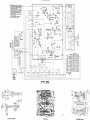
SCHEMATIC DIAGRAM
THE TC28 HYBRIDER
BLOCK DIAGRAM
FOIL SIDE
COMPONENT SIDE