1
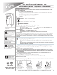
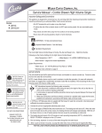
Wilbur Curtis Company, Inc. Service Manual, 1 Gallon Brewers Important Safeguards/Symbols This equipment is designed for commercial use. Any servicing other than cleaning and routine maintenance should be performed by an authorized Wilbur Curtis Company Service Technician. • DO NOT immerse the unit in water or any other liquid • To reduce the risk of fire or electric shock, DO NOT open service panels. There are no user serviceable parts inside. • Keep hands and other items away from hot areas of the unit during operation. • Never clean with scouring powders or harsh chemicals. Symbols: WARNINGS – To help avoid personal injury Important Notes/Cautions – from the factory Models Included • TP1T • TP1TT • TP1S • TP1ST Sanitation Requirements Installation This Curtis unit is pre-set and ready to go from the factory. Factory settings for this unit are: • Brew Temperature = 200°F • Water Bypass = On LARGE & MEDIUM brew only CAUTION: Equipment must be installed to comply with applicable federal, state, and local plumbing/electrical codes. CAUTION: Follow this setup procedure before attempting to use this unit. Failure to follow these instructions can result in injury and/or void of warranty. CAUTION: DO NOT connect the unit to hot water supply. The inlet valve is not rated for hot water. • Brew Volume = Set to vessel requirements (specific based on model). System Requirements: • Water Supply 20 – 90 PSI (minimum flow rate of 1 gpm) • Electrical: See electrical schematic. Setup Steps 1. The unit should be level (left to right - front to back), on a secure surface. 2. Connect the water line to the water inlet fitting on the rear of the unit. Water volume flow to the machine should be consistent. Use tubing sized sufficiently to provide a minimum flow rate of one gallon per minute. NOTE: A water filtration system must be used to help maintain trouble-free operation. In areas with extremely hard water, we highly recommend the use of a Curtis approved water filter. For our full line of filters, please log on to www.wilburcurtis.com. A water filtration system will greatly prolong the life of the unit and enhance the quality and taste of the product. NSF International requires the following water connection: 1. A quick disconnect or additional coiled tubing (at least 2x the depth of the unit) is required so that the unit can be moved for cleaning. 2. This unit must be installed with adequate backflow protection to comply with applicable federal, state and local codes. 3. Water pipe connections and fixtures directly connected to a portable water supply shall be sized, installed and maintained in accordance with federal, state, and local codes. 3. Connect the unit to electrical outlet with appropriate amperage rating (see serial tag on machine). ISO 9001:2008 REGISTERED WILBUR CURTIS CO., INC. 6913 West Acco Street Montebello, CA 90640-5403 For the latest information go to www.wilburcurtis.com Tel: 800-421-6150 Fax: 323-837-2410 4. Once power has been supplied to the unit, flip the toggle switch to the ‘ON’ position (located on the rear of the unit), the water tank will begin to fill. When the water level in the tank reaches the probe, the heating element(s) will turn on. 5. Water in the heating tank will require approximately a half hour before reaching operating temperature (factory setting of 200°F). Where applicable, turn on the Universal Control Module (UCM). When the unit reaches operating temperature, it will display “READY TO BREW”. FOR THE LATEST SPECIFICATION INFORMATION GO TO WWW.WILBURCURTIS.COM 1 BREWING INSTRUCTIONS Use only coffee or water in the ThermoPro dispenser. Do not use the server to dispense any other beverage. Preheating the server with hot water is recommended. The single head brewer is show below, the twin head brewer is similar. 1. Place a clean and empty server on the deck. Server should be centered below the brewcone of the brewer. 2. Make sure the unit is up to brewing temperature and the LCD screen reads READY TO BREW. 3. Place a filter in the brewcone and pour in the correct measure of ground coffee for the brew volume. 4. Slide the brewcone into the brew rails. 5. Select and press desired brew button (LARGE or SMALL). The unit will start the brew cycle. 6. Allow coffee in the brewcone to drip out completely before removing the insulated server. POUR COFFEE INTO BASKET INSERT BREWCONE INTO RAILS PRESS THE BREW BUTTON WARNING – THERMOPRO SERVERS MAY BE HEAVY WHEN FILLED. CARE MUST BE TAKEN WHEN TRANSPORTING TO AVOID DROPPING OR SPILLING. Tank Temperature Check To check the temperature of the water within the heating tank, make sure brewer is on and Ready to Brew is displayed. Press and hold the button (see illustration, page three) for 5 seconds. The water temperature inside the tank will be displayed. 2 Control Module Menu Tree The flow chart displays the sequence of menu item that can be accessed through the UCM. Various menu items will immediately exit the programming mode when selected. Other menu items, when selected, will continue to the next item in the menu list. IMPORTANT NOTE: All programming selections are performed with the three center buttons. The symbols below the buttons are: Scroll LEFT SELECTION or ENTER to save new parameter Scroll RIGHT 3 PARTS DIAGRAMS Twin 1 Gallon Brewer 32 1 2 12 34 33 5 3 4 6 13 14 7 8 15 16 9 18 19 10 17 27 35 20 30 22 23 21 31 11 29 24 25 26 4 27 28 PARTS LIST TP1T & TP1TT ITEM № 1 2 3 4 5 6 7 7A 8 9 9A 10 11 12 13 14 15 16 17 18 19 20 21 22 23 24 25 26 27 28 29 30 31 32 33 34 35 PART № DESCRIPTION WC-5421 WC-37121* WC-2977-101K WC-4212-02* WC-37122* WC-37231* WC-1809 WC-1806* WC-29050 WC-59022 WC-61612 WC-8559 WC-3417 WC-2402P WC- 847* WC- 102* WC-8591* WC-3518 WC-3503 WC-37008* WC-43067* WC-62033 WC-5502-01* WC-37317 WC-37357 WC-4382 WC- 522* WC-43055 WC-37266 WC-1438-101* WC- 934-04* WC-5231* WC-5310* WC-37132* WC-3765L* WC- 844-101* GEM-6 COVER, TOP VALVE, LIQUID DISPENSING LEFT 120VAC KIT, SPRAYHEAD FITTING ULTEM NUT, 5/8-18 JAM ULTEM VALVE, DUMP 120V 12W RIGHT KIT, UCM & LABEL TPS1T/TP1TT FAUCET, HOT WATER W/JAMNUT SEAT CUP, FOR WC-1809 (NOT SHOWN) SPRAYHEAD, AMBER ADVANCED FLOW PANEL, FRONT TPS1T PANEL, FRONT TP1TT RELAY, SOLID STATE 40A W/HEAT SINK BREW CONE,ASSY W/SPLASH POCKET BRN COFFEE ELBOW, 3/8”FL x 3/8” NPT PLATED VALVE, INLET 2GPM SWITCH, TOGGLE 125/250 VAC RESISTIVE CAPACITOR, X2 LEG, GLIDE 3/8-16 STUD SCREW LEG, 3/8-16 STUD SCREW (NON-GLIDE) KIT, HEATING TANK LID GASKET, TANK LID TANK, COMPLETE GEMTS W/ULTEM FTTNGS KIT, PROBE ASSY WATER LEVEL W/O-RING & NUT KIT, STRAIGHT FITTING & BUSHNG GEN USE KIT, STRAIGHT PLASTIC FITTING AND BUSHING 12MM GUARD, SHOCK HEATING ELEMENT THERMOSTAT, HI LIMIT HTR DPST 277V 40A GUARD, SHOCK RESET THERMOSTAT KIT, FITTING TANK OVERFLOW SENSOR, HEATING TANK ELEMENT, HEATING 2.5KW 220V COMPOUND, SILICONE 5 OZ TUBE TUBING, SILICONE, 5/16” I.D. ( 1 FT.) KIT, VALVE REPAIR USE ON WC-820WDR,WC-821WDR KIT, VALVE REPAIR USE ON WC-847 VALVE, BY-PASS 120V NON-ADJ W/RSTRCTR FILTER, 500/PKG 12½ x 4 * RECOMMENDED PARTS TO STOCK. 5 PARTS DIAGRAMS TP1S & TP1ST 1 8 9 2 10 11 3 4 34 32 12 5 6 7 13 33 14 17 15 31 16 18 19 20 21 35 30 25 22 26 23 24 27 29 28 6 PARTS LIST TP1S & TP1ST ITEM № PART № DESCRIPTION 1 2 3 4 5 6 7 8 8A 9 9A 10 WC-58117 WC-37266 WC-5502-01* WC-37317 WC-4394 WC-43055 WC-1438-101* WC-61556 WC-61556-101 WC-43068* WC-43068-101* WC-62037 COVER, TOP KIT, FITTING TANK OVERFLOW KIT, PROBE ASSY WATER LEVEL W/O-RING & NUT KIT, STRAIGHT FITTING & BUSHNG GEN USE GUARD, SHOCK HEATING ELEMENT GUARD, SHOCK RESET THERMOSTAT SENSOR, HEATING TANK COVER, TANK (FOR UNITS MADE BEFORE 1/2010) LID, TANK TP1S GASKET, TANK LID (UNITS MADE BEFORE 1/10) GASKET, TANK LID RECTANGULAR TP1S TANK COMPLETE TP1S/TP1ST 11 12 13 14 15 16 17 18 19 20 21 22 23 24 25 26 27 28 29 29A 30 31 32 33 34 35 WC-37357 WC- 904-04* WC- 522 * WC- 844-101* WC-37122* WC-2977-101K WC-8559 WC-37287* WC-39580 WC-38439 WC-1809 WC- 103* WC-8591* WC- 847* WC-29050 WC-2402P WC-3518 WC-3503 WC-61622 WC-61551 WC-3417 WC-3765L* WC-37132* WC-5231* WC-5310* GEM-6 * KIT, STRAIGHT PLASTIC FITTING AND BUSHING 12MM ELEMENT, HEATING 1.6KW 120V W/JAM NUT THERMOSTAT, HI LIMIT HTR DPST 277V 40A VALVE, BY-PASS, NON-ADJUSTABLE W/RESTRICTOR KIT, DUMP VALVE RIGHT KIT, SPRAYHEAD FITTING ULTEM RELAY, SOLID STATE 40A W/HEAT SINK KIT, UCM & OVERLAY 2-BATCH TP1S LABEL, UCM OVERLAY 2-BATCH LABEL, FRONT HOT WATER FAUCET, HOT WATER W/JAMNUT SWITCH, TOGGLE NON-LIT DPST 25A 125/250VAC CAPACITOR, X2 VALVE, INLET 2GPM SPRAYHEAD, AMBER ADVANCED FLOW ELBOW, 3/8”FL x 3/8” NPT PLATED LEG, GLIDE 3/8-16 STUD SCREW LEG, 3/8-16 STUD SCREW (NON-GLIDE) COVER, FRONT SS TP1ST TALL COVER, FRONT SS TP1S SHORT BREW CONE,ASSY W/SPLASH POCKET BRN COFFEE KIT, VALVE REPAIR USE ON WC-847 KIT, VALVE REPAIR USE ON WC-844WDR/WC-821WDR COMPOUND, SILICONE 5 OZ TUBE TUBING, SILICONE, 5/16” I.D. FILTER, 500/PKG 12½ x 4 * RECOMMENDED PARTS TO STOCK. 7 CLEANING Regular cleaning of the coffee brewer will maintain the highest quality coffee your equipment is capable of producing. Proper cleaning is essential to maintain a fresh and appealing look to your coffee service. To clean the coffee brewer components, prepare a mild solution of detergent and warm water. 1. First turn off the brewer using the ON/OFF button on the front control panel. 2. Wipe all exterior surfaces with a damp cloth, removing spills and debris. 3. Slide the brewcone out and clean it. Thoroughly wipe sprayhead area with a damp cloth. 4. Wash the brewcone. Use a soft bristled brush for hard to clean areas. Wash both parts with a detergent solution or put these parts through a dishwasher. CAUTION Do not use harsh powders or cleansers containing chlorine. Cleaning and Sanitizing Instructions for TLXG01 Server CAUTION Do not immerse server in water. Do not place in server dishwasher. Do not use harsh powders or cleansers containing chlorine. Do not use a wire brush or pot scourer to clean inside liner. These cleaning and sanitizing instructions are only a guide line to be used for the cleaning and sanitizing of the TLXG01. Your current in-house cleaning and sanitizing methods may be just as effective. For cleaning and sanitizing of the TLXG01, the three sink method is recommended. This method consists of a sink of water filled with a detergent and water solution, a fresh water rinse, and a sink filled with an aqueous sanitizing solution. Immerse parts in commercial BarTabs/Sani-Tabs sanitizing solution. The solution must be warm (75°F.) Let the parts soak at least one minute. 1. Daily, Rinse the unit after use. a. Open unit and empty contents completely. b. Rinse unit with hot water, then open faucet to drain. c. Wipe outside of unit with clean cloth moistened with cleaning solution. 2. Cleaning and server assembly. a. Fill the unit with cleaning solution. With a sponge brush, thoroughly clean inside liner. b. Rinse the unit using a fresh water rinse. 3. Clean and sanitize the lid assembly. a. Remove lid from unit and submerse it in cleaning solution, cleaning thoroughly. b. Using the supplied brush, clean inside the filling tube. c. Rinse with clean water. d. To sanitize, submerse in sanitizing solution for 5 minutes then air dry completely. 4. Cleaning the faucet and gauge glass. a. Unscrew the bonnet/handle assembly from the faucet. b. Remove gauge glass from unit and brush out with cleaning solution. c. With the faucet removed, clean the silicone elbow fitting (Tank to Faucet Tube). Use the tube brush soaked in cleaning solution, inserted through the faucet shank. d. Clean and rinse parts. e. To sanitize, place in sanitizing solution for 5 minutes, remove and air dry. 5. Sanitizing the assembled TLXG01 server. a. Fill a clean server with sanitizing solution. Allow to sit for 5 minutes then drain through the faucet. b. Place body assembly upside down on rack to thoroughly air dry. 8 ROUGH-IN DRAWING TP1T & TP1TT ROUGH-IN DRAWING TP1S & TP1ST 16.625" 9.25" (42.2 cm) (23.5 cm) 36.625" (93.0 cm) 27.875" (70.8 cm) 29.500" (74.9 cm) 20.750" (52.7 cm) 20.250" 24.625" (51.4 cm) (62.5 cm) 16.125" (41.0 cm) 16.500" (41.9 cm) 9 ELECTRICAL SCHEMATIC TP1T & TP1TT 10 ELECTRICAL SCHEMATIC TP1S & TP1ST 11 Product Warranty Information The Wilbur Curtis Company certifies that its products are free from defects in material and workmanship under normal use. The following limited warranties and conditions apply: 3 Years, Parts and Labor, from Original Date of Purchase on digital control boards. 2 Years, Parts, from Original Date of Purchase on all other electrical components, fittings and tubing. 1 Year, Labor, from Original Date of Purchase on all electrical components, fittings and tubing. Additionally, the Wilbur Curtis Company warrants its Grinding Burrs for Forty (40) months from date of purchase or 40,000 pounds of coffee, whichever comes first. Stainless Steel components are warranted for two (2) years from date of purchase against leaking or pitting and replacement parts are warranted for ninety (90) days from date of purchase or for the remainder of the limited warranty period of the equipment in which the component is installed. All in-warranty service calls must have prior authorization. For Authorization, call the Technical Support Department at 1-800-9950417. Effective date of this policy is April 1, 2003. Additional conditions may apply. Go to www.wilburcurtis.com to view the full product warranty information. CONDITIONS & EXCEPTIONS The warranty covers original equipment at time of purchase only. The Wilbur Curtis Company, Inc., assumes no responsibility for substitute replacement parts installed on Curtis equipment that have not been purchased from the Wilbur Curtis Company, Inc. The Wilbur Curtis Company will not accept any responsibility if the following conditions are not met. The warranty does not cover and is void under the following circumstances: 1) 2) 3) 4) 5) 6) 7) 8) 9) Improper operation of equipment: The equipment must be used for its designed and intended purpose and function. Improper installation of equipment: This equipment must be installed by a professional technician and must comply with all local electrical, mechanical and plumbing codes. Improper voltage: Equipment must be installed at the voltage stated on the serial plate supplied with this equipment. Improper water supply: This includes, but is not limited to, excessive or low water pressure, and inadequate or fluctuating water flow rate. Adjustments and cleaning: The resetting of safety thermostats and circuit breakers, programming and temperature adjustments are the responsibility of the equipment owner. The owner is responsible for proper cleaning and regular maintenance of this equipment. Damaged in transit: Equipment damaged in transit is the responsibility of the freight company and a claim should be made with the carrier. Abuse or neglect (including failure to periodically clean or remove lime accumulations): Manufacturer is not responsible for variation in equipment operation due to excessive lime or local water conditions. The equipment must be maintained according to the manufacturer’s recommendations. Replacement of items subject to normal use and wear: This shall include, but is not limited to, light bulbs, shear disks, “0” rings, gaskets, silicone tube, canister assemblies, whipper chambers and plates, mixing bowls, agitation assemblies and whipper propellers. Repairs and/or Replacements are subject to our decision that the workmanship or parts were faulty and the defects showed up under normal use. All labor shall be performed during regular working hours. Overtime charges are the responsibility of the owner. Charges incurred by delays, waiting time, or operating restrictions that hinder the service technician’s ability to perform service is the responsibility of the owner of the equipment. This includes institutional and correctional facilities. The Wilbur Curtis Company will allow up to 100 miles, round trip, per in-warranty service call. RETURN MERCHANDISE AUTHORIZATION: All claims under this warranty must be submitted to the Wilbur Curtis Company Technical Support Department prior to performing any repair work or return of this equipment to the factory. All returned equipment must be repackaged properly in the original carton. No units will be accepted if they are damaged in transit due to improper packaging. NO UNITS OR PARTS WILL BE ACCEPTED WITHOUT A RETURN MERCHANDISE AUTHORIZATION (RMA). RMA NUMBER MUST BE MARKED ON THE CARTON OR SHIPPING LABEL. All in-warranty service calls must be performed by an authorized service agent. Call the Wilbur Curtis Technical Support Department to find an agent near you. 11/11/[email protected] . ECN 15461 . revG 3/6/[email protected] . ECN 14810 . revF WILBUR CURTIS CO., INC. 10/11/[email protected] 14475.revE 6913 Acco St., Montebello, CA 90640-5403 USA 4/1/[email protected]_revD 12/9/8 . 10.7 . ECN 10134Phone: revC 800/421-6150 Fax: 323-837-2410 1/18/8 . 12.8 . ecn 9443 Technical Support Phone: 800/995-0417 (M-F 5:30A - 4:00P PST) 1/25/07 . 13.7 . ecn 8745 Web Site: www.wilburcurtis.com E-Mail: [email protected] FOR THE LATEST SPECIFICATION INFORMATION GO TO WWW.WILBURCURTIS.COM 12 Printed in U.S.A. 11/2013 F-3484 Rev G