1
Motorola Micor transmitter for repeater use
By Karl Shoemaker
Introduction:
This document is written to include interested people in serious construction of a quality product. Its rather
technical, however, if you have a basic electronics background with some repeater building experience
this should not be an issue. Some of it’s dry reading however, you need to spend time on this to better
understand advanced circuits, later on. Understanding schematic drawings is required. If you are new at
the repeater operation you might want to seek experienced help. Allow plenty of time to construct each
radio, especially the first one. No free technical support is available however, some printed documents
are available on an occasional bases, for a modest cost for P & H. The project is designed for amateur
radio (not commercial) and is open for discussing, changes and improvements without notice. Should you
feel qualified you are welcome to deviate from the Author's design. Images in this document may be used
to illustrate a point only and may have been taken at different stages of research and development
therefore, may not show the end “product” in some cases.
Overview:
Motorola made a “Micor” series of radios; both base station and mobile. This discussion is mainly on the
mobile which was manufactured in the 1970's. Its a very rugged, heavy mobile radio unit (drawer unit, if
you will) that works with an "accessory group" consisting of a power cable, speaker, control head and
microphone. The basic ordering option was 1, 2, 3, or 4-frequency channels controlled with the head.
Acronyms, Definitions, semantics and Theory basics:
To be very clear on this philosophy, we will start with very basic theory. Radio systems send intelligence
(voice, data, etc.) by modulating the originating transmitter and decoding (detecting) this modulation at
the far end receiver back to something usable to be understood. How well this is understood depends
greatly on how well the system is set up. Just about anyone can "throw" a system together to make it
work, somewhat.
Amateur radio can develop the art of radio and improving operating practices in this area. This can set a
good example for others, including the commercial industry, to what some amateur radio systems are
capable of doing and to provide public service communications in time of need. This includes the
technical side, to produce a high performance repeater or link.
A typical (commercial) system uses the audio portion of 300Hz~3KHz for signals. This document covering
system performance will be somewhat different. It also calls for good technical management. For one,
technician organization and discipline is necessary. Plan on what you want to do for a system design and
stick to it. Force yourself to keep good practices. One good practice is to establish level references. Some
call these "benchmarks" or "baselines". While old methods used linear (microvolts, watts, etc) units of
measure, most SRG designs and operations use logarithmic units in "dbm". Once accustomed, it's easier
to see the entire picture this way, when designing a system or checking system performance and keeps
the guesswork out of troubleshooting a subtle level problem.
Most radio systems in the VHF, UHF (and microwave) are line-of-site for the radio paths. On the ground a
path has limited range. From high (remote) sites greatly increase this. A “repeater” is a generic term for
user’s signals to be received (input) and retransmitted (output). This greatly increases radio coverage,
especially at high locations. A “link” is a one-way transport method for support of such a repeater. For
example, a repeater’s (input) receiver may need to be “downlinked” to a central control point, such as a
voter or connection to the outside world (telephone, internet, etc.). From this control point the system
output can be “uplinked” back up to a high transmitter (output) for the users to enjoy wide coverage of
such a system. In this case would be a multiple site repeater (system of links, etc.) SRG design
specifications call for a better way, as you will see in this documentation.
References can be expressed in a few acronyms. Normally, a tone of 1 KHz (sometimes 1004 Hz) is
used for a testing a "2-way" VHF-UHF transmitter or receiver. TTL ( Test Tone Level ) is referenced to
1
100% system modulation; in this case F.M. (Frequency Modulation). FM is also referred to "deviation" (of
the carrier, at an audio rate). For amateur radio 100% system modulation is normally + - 5 KHz. Other
areas/States and/or commercial services have different bandwidth standards such as +- 2.5 KHz. For this
document we will only cover the former (5 KHz deviation).
TLP ( Test Level Point ) refers to a measurement point (normally on equipment) in reference to TTL. TLP
provides easy reference to any parts of the system for measurement and alignment. 0 dbm is referenced
to 1 milliwatt at 600 ohms. Therefore, a transmitter AF input with a TLP of 0 dbm, with a TTL of 0 dbm
tone input, would fully modulate the system. If the far end receiver was set up the same its output a 0
dbm tone as well. A 6-dB drop in (voltage) level would reduce the modulation in half, and so on. In
general, levels are stated in transmit-receive (Tx-Rx) order. Therefore, an audio (VF) "drop" TLP of 0/0
would mean a Tx TLP of 0dbm, Rx TLP of 0dbm. Absolute levels are specific-measured (operating)
levels, not to be confused with TTLs.
Sometimes operating levels are not at TTL. In this case a level would be so many dB "down" from TTL, or
just called "xx down". For example, CTCSS (sub-audible) tones normally are 18 dB down. (1/8 deviation
from voice, or 18 dB down from max-voice and/or TTL). To avoid technician confusion two sets of
numbers are sometime used in diagrams and on the physical equipment's ports or I/O connections.
Figures in parenthesis are the TLPs. Non-parenthesis figures are (absolute/actual) operating levels, and
as mentioned before, may be at different levels from the TTLs.
Levels below 0 dbm are negative, while above are positive. Take this into consideration when working
with system gains or losses. Normally the negative levels have a minus in front of the number, while
positive have a plus sign. This is also true for absolute levels (as opposed to TTLs). For example, most
transmitters run a +42 dbm while most receivers’ sensitivity run a -117 dbm for 20 dB quieting. These
levels are at the transmit and receiver ports, respectively. Also known as "TOR", Top Of Radio, or Top of
Rack is before the transmission line and antenna outside on the tower. The latter parts can be figured in
for the entire system's losses or gains.
Single digit numbers of "1" and "0" in parenthesis or brackets “[ ]”, are not to be confused with TLPs. In
this case these 1s and 0s identify the logic state of a gate, or other TTL/CMOS I/O driver circuit, and so
forth. Another aid to avoid confusion between logic states and a TLP is that the latter normally would have
a " + " or " - " before the number. For example, a TLP of -14.8 is the audio input controlled by a logic gate
of [1], being a normal logic "high". One last word on the logic state. The parenthesis indicates a state in
normal standby/no activity condition. As a side note, "TTL" mentioned above has nothing to do with "TTL
logic", a type of IC series.
Most “TIMM”s and AC voltmeter scales are in “dbm”. When measuring across a circuit you may need to
have the meter in bridge mode, being high impedance as not to load down what you are measuring. In
such cases a more accurate term of level would be “dBu”. Having said this, dbm reading in bridge mode
is still understood for a specific (absolute) level measurement using the “dbm” term.
The term "PTT" ( Push To Talk ) came from a button on a radio’s microphone. For this documentation
PTT will describe an active going "low" for DC functions, such as transmitter keying ("PTT Input"). It also
will describe a receiver's COR line driving a NPN transistor, with the open collector being "Receiver PTT
Out", or just "PTT Out". "PTT 1" will describe this function however, with a buffer, such as the output of
the COR/AF board, which changes state for user signal change of status. This function would be used for
audio switching, such as Auto-Patch audio routing. "PTT 2" will describe a buffered, and “hangtime/tail”
output of the COR/AF board, to keep a repeater's transmitter keyed up (AKA tail) for normal back-andforth conversations of the users of such system(s). One or both types of PTTs may be time-out controlled.
The term "COR" came from the old tube days of "Carrier Operated Relay" whereas, a tube receiver had a
point, when its squelch opened, a tube (switch/valve) drew current through a relay's coil, to give some
contact closure, to key the associated repeater's transmitter. As the solid state technology came in the
later 1960's the term stayed with repeater operation, even though the Author saw no "relay" in most
modern repeaters and felt the "relay" term should have been replaced with the term of "squelch", since it's
the receiver's squelch that does the signaling. This would be called" COS", meaning a "Carrier Operated
Squelch".
2
Both terms are correct and this gets down to semantics or content of a discussion. After careful
consideration of modern technology used in the LMR field by amateurs and professional alike, including
recent repeater product terminology and to the fact that repeater stations in the early years were also
called "Relays" whereas, the station would "relay" a signal rather than "repeat" a signal, the Author
decided to stay with the majority's term of "COR", to avoid reader confusion. Therefore, this and other
SRG documentation will reflect this decision. "COS" may also be used to describe a "Carrier Squelch" as
a part of a receiver. "CS" will be reserved to describe "Carrier Squelch" as a receiver's mode of operation,
verses "TS", "PL" or "CTCSS" to describe a "Tone Squelch", "Private Line" or "Continuous Tone Coded
Squelch System".
"PLI" means Private Line Indicator (or Input). It's also similar to a CTCSS line out of a tone decoder.
"HUB" means Hang Up Box. Motorola's uses a "closed loop" and a HUB for mobiles and base station
control. "AND squelch" means it takes both carrier + tone to activate a COR board, transmitter or system.
AND squelch is also referred as a variable sensitivity squelch whereas, the squelch setting affects activity
threshold. An "OR" squelch does not whereas, it "bypasses" whatever squelch setting, using only tone to
keep it active. More is discussed, later in this document.
SRG means Spokane Repeater Group, a non-profit organization for the development of equipment
operation and enhancement for the benefit of other amateur radio operators for communications support,
especially for Public Service (emergency traffic) and other hobby type discussions.
Other definitions, acronyms and other "shortcuts" are for practical reading and document space. For
example, names are truncated only after the full name is established. This avoids misunderstandings.
For example, the parts list shows several manufacturers in truncated form, such as, Mouser Electronics (a
major parts supplier) is later referred to as "Mouser".
FM:
Frequency modulation is the common way to send intelligence in the LMR analog world. There are two
ways to frequency modulate a transmitter; PM and FM. Phase modulation is the easiest design with good
frequency stability however, lacks audio response. However, PM has “natural” pre-emphasis which works
well for LMR standard. On the other hand, FM has much better response (flat audio) at the cost of more
complex engineering to keep stability. With synthesized/PLL transmitters this is major consideration.
However, later technology in design has allowed FM to perform well in LMR systems. It’s also referred to
as “direct FM”. With careful design changes, FM can perform well and is the method used for all SRG
equipment.
A quartz crystal is normally used to control the frequency of an oscillator. A capacitor across the crystal
can fine-adjust the frequency in the form of “warping” it. Transistors and diodes have P-N a junction inside
the case. The junction has a “space” in the middle in the form of capacitance called the “depletion zone”.
By applying reverse voltage will affect the zone. More reverse voltage results in more space, causing less
capacitance. In a RF circuit this can mean higher frequency, in general. Applying “intelligence” in the form
of audio (acv/voice) will cause the RF circuit to change in frequency at the same rate, thus, creating
(direct) FM. Special diodes are made for this purpose, called a varactor diode (veri-cap). There’s a range
the diode will work in, causing a linear frequency change from the voltage change on the diode. A “bias”
DC voltage is normally applied across it to stay in this range. The modulation “rides” on top of this bias.
Careful design is necessary to create good symmetry (waveform) on a frequency modulated RF carrier.
This is practiced for SRG projects.
Most PM transmitters have the diode in series with the crystal causing a phase difference from the
fundament frequency, while most FM transmitters has the diode in parallel to the crystal. For FM
transmitters, most have the anode to (common) ground and usually across the crystal.
Modulation and Deviation are the same results when talking about FM. Deviation of 5 KHz means 5 KHz
above the center frequency and 5 KHZ below the center frequency, making a total bandwidth of 10 KHz.
There is other “energy” in the form of sideboards, which won’t be covered in this document.
The fundamental crystal frequency will be converted by multiplying its frequency to obtain the (final)
operating frequency. For example, a typical LMR VHF transmitter would be 12 times; or a tripler, driving
3
another doubler, driving a final doubler. (Fc=12 MHz x 3 x 2 x 2 =144 MHz). Frequency multiplication also
multiples the modulation of the fundamental. Since this arraignment multiples the crystal frequency 12
times it won’t take much capacitance change to obtain 5 KHz modulation (deviation) at the operating
frequency. The diodes come in various specs, for capacitor range. Typical is 10 ~ 13 pf for LMR.
The project - - - Repeater usage:
For repeater use will require a custom-build chassis. You are required to know the micor inside and out.
This is especially true if you are converting a high range (150.8-174 MHz) transmitter to a low range for
the amateur band. Repeater building experience is needed as well. One little component mistake can
cause hours of frustration. If this is your first time seek help from a local repeater owner to avoid problems
and equipment damage.
For repeater use will be a single frequency operation. The OEM mobile radio has several sections inside.
Two of them are discussed here; the separate transmitter and receiver sections, each of can be easily
removed and mounted on a 2RU 19" rack panel. The appropriate controls then can be installed on this
panel, eliminating the need for separate cables and controls, both of which take up space and clutter in a
repeater cabinet or rack. The rest of the mobile unit is discarded or otherwise used only for misc. parts.
This unit is set up for negative ground.
This arrangement is similar to the "compa" station unified (or non-unified) chassis, without the control
circuitry. However, one large advantage to using a mobile is each part can be installed at separate sites
with minimal space. Therefore, each of the transmitter and receiver will be a covered on separate
documents found on SRG’s web site. For this document only the transmitter is covered. The first custombuilt transmitter pre-1990 started the compact package. Shown here is serial #1.
Serial 2 changed to the white panel standard. Shown here is the front of a finished transmitter. Notice
there's a switch function to "lock on" the PTT line for transmitter testing under load. It was decided a ONCenter OFF-ON switch is sometimes awkward to use; disable being in the "center" position; one may run
the switch to the down position and keep the PTT on, so this was changed to a ON-ON switch as shown
here.
4
2014 redesign/updates:
(Serial 4 and later)
A logical and standard layout needed to be realized. This includes additional indicators such as 12v, 9.6v
keyed 9.6, PA power and PTT activity in the appropriate colors. The correct terminal block placements
were done for consideration of the exciter’s I/O runs, etc. and short PA wires. Behind the panel, the
chassis position was moved to the left for improved fuse and RF port clearance on the right side. The
three switches on the panel are arraigned properly. The left is the main power, middle PTT control and
right PTT lock-on test position. Both PTT switches have to be up for this test function to work. A red
flashing light reminds you it’s in this mode, for testing. The picture was taken during a load test and is the
final layout.
Exciter:
The exciter board is the heart of the transmitter. It has the frequency determining element (channel
element with the crystal), the modulation section and all the multiplier and amplifier stages to a usable
level (of +26dbm) to drive the PA. The type of modulator is very important for a flat system therefore, only
the 4-pin exciter board is used for this project (older versions with the 3-pin phase modular where
modified for direct FM).
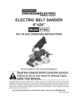
As of 2014 it’s capable of 2-frequency
operation. The F1 and F2 enable wires
run out to TB1 for external control. In
the picture above notice the “enable”
lug-jumper on TB-1 terminals 7 and 8
for normal F1 operation. Terminal 10 is
the fan control (discussed later).
Shown on the left are the two audio
coupling capacitors that now use the
(old) F4 line as the input (flat audio).
TLP is about +3 dbm.
To start, remove C457 and replace that spot with a wire jumper (now called JU457). Also, jumper this
point to the eyelet feeding P902 pin 5. This now functions as a ground run. Remove C410 and replace
with a 4.7uf, 25 v electrolytic capacitor with positive lead going to P902 pin 7). This is a general filter for
the regulator. Optionally (for general cleanup) you can remove JU401, JU402, JU403, JU404, C465, and
C466. Remove C405; then remove C463 and install a new tantalum with the leads reversed; the positive
lead going to CE1 pin 4 and the negative lead going to the F4 select line (where part of C405 was). For
the second frequency option install the same value to with its positive lead going the CE2 pin 4. The other
lead can be shared with the F1 cap’s negative lead (going to the F4 select line). This is now the "Tx AF
input" (P902, pin 18).
The board will need +12v (A+) and regulated +9.6 to operate. For OEM (mobile), the latter gets it from a
regulator on the middle board (which is not used for this project). For this project the LM-7810 3-pin
regulator is used. The output goes through a simple rectifier diode (6 tenths voltage drop) causing the
output of 9.4v which is close enough to the stock "9.6" voltage.
5
Control:
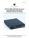
To control the keyed circuits a TIP42 transistor is used with its
associated parts. The physical location has been under
research for several years. The left image is the older,
obsolete mounting location for the 9.6 regulator (the PTT
switch was located elsewhere).
More recent versions (2009 and later) have the parts mounted
on P401 which was the PL pins that are not being used. First,
to make is the regulator with a very small "footprint". Then
install a .22 uf cap on its output, which is required to filter noise
at this point. Then add the dropping diode to get the 9.4v
output. This "sub-assay" can be later mounted on the P401
pins.
Below shows several being made as a production “line” to
produce several transmitters with their regulators.
Next, remove P401 pin 1 and cut the rest of the pins down in
length, so the top of the installed parts will clear the chassis
and tin them. Install the 10v regulator and PTT switch on the
pins, per the diagram for the interconnect and these pictures.
Install a diode (cathode) on pin 1 with a 1K resistor in series
with its lead to the switch’s base. The diode isolates the 9.6v to
(outside) 12v equipment’s
PTT and other (LED)
circuits on the front panel. .
Remove JU405 and install
a 2.2K resistor in its place.
(2.7K is okay for a
substitute.)
In the event the components needed replacement is an easy task working with the pins as solder mounts.
In the right picture notice the blue capacitor next to Q406. If its larger in size move it slightly inward
(angled leads) so it clears the chassis (rail) when installed.
6
Here’s the modified exciter board to the extent wires are soldered to the P904 (I/O) pins with heat shrink
to increase reliability. Some of the unused pins are removed to assist the ferrite bead clearance (some
others are left). The beads can reduce RFI on the lines if the site is (RF) hostile. A drop of glue will keep
them in place. The unused pins that were removed are 2,3,5,6,10 and 14.
Control versions:
To control the transmitter some 9.6v stages are “hot” during standby, while latter 9.6v stages are “cold”
(mainly the multiplier stages). When keyed they become “hot”, causing the transmitter to output RF. Also,
the OEM arraignment has Q406, the last output stage, (Q408 in the compa style) “live” all the time from
the 12v (A+) source. Being a class C device; it only has output when the earlier stages are “hot”. For this
project this section is kept as OEM.
There were several different SRG versions of exciter boards developed. This involves the control
method, such as what circuits are “hot” during standby and which ones are “switched” (to key the
transmitter). These versions were developed in September 2009, based on research from 2000, using the
TLD5132A exciter board. There are several versions; "A" from the 1990's and recently, September 2009
version "B" was developed however, not proven in service. Version “C” appears to be the best method
and is the version to be used for all SRG transmitters. All versions are reviewed here:
Version A ; Only the channel element is running full time:
This version keeps the crystal and channel element running full time via the continuous 9.6v line. This
improves stability. The other circuits after the CE are off during standby condition; that would include
pulse amplified IC401, mic audio IC402, CE buffer Q401, pulse amplifier Q402, and the multiplier stages
of Q403, Q404, and Q405, via the keyed 9.6v line.
For this version, cut the PCB run between IC401, pin 9 and CE4, pin 2 and C406 area. There's a straight
run at IC401; right near it's pin 16 is a good place to make the cut. This isolates the continuous and keyed
9.6v lines. Jumper P902, pin 4 to pin 8. This feeds the voltage input of the PTT switch and other
continuous 9.6v circuits. Jumper P902, pin 9 to pin 13. This feeds the keyed 9.6v circuits and components
such as the IC and multiplier stages. Jumper the eyelet near P401, pin 7 to the area of the cut, just before
C406. There are two eyelets that work great for this; one next to the pin 7 and the other above C406. This
completes continuous 9.6v to feed only the channel element continuously, during standby state.
Version B ; The channel element, some transistors and IC are running full time:
This version keeps the crystal and channel element running full time via the continuous 9.6v line. This
improves stability. Some of the other circuits after the CE are also running during standby condition via
the continuous 9.6v line; that would include pulse amplifier IC401, mic audio IC402, CE buffer Q401 and
7
pulse amplifier Q402. The multiplier stages of Q403, Q404, and Q405 are off during standby state, via the
9.6v keyed line.
For this version, cut the PCB run between P401 pin 9 and Q402 emitter. There's a straight run closer to
the former to make the cut. This isolates the continuous and keyed 9.6v lines. Jumper P902 pin 13 to
P902 pin 8 and pin 4. This completes the continuous 9.6v line. Jumper P401 pin 3 to pin 9. This
completes the keyed 9.6v line. This version has not been tested/proven in actual service.
Version C ; Only the channel element is running full time. This version is the same as version A except
two shorter jumpers take the place of that one long one running over to the C406 area (for the continuous
9.6v); it looks cleaner. To recap, the procedure for version C:
Cut the PCB run between IC401, pin 9 and CE4, pin 2 and C406 area. There's a straight run at IC401;
right near it's pin 16 is a good place to make the cut. This isolates the continuous and keyed 9.6v lines.
Next, jumper P902 pin 4 to pin 8 and pin 17. Then, jumper CE3 pin 1 (old F3 line) to pin 2. This feeds the
continuous 9.6v to the channel elements and PTT switch. Then jumper P902, pin 9 to pin 13. This feeds
the keyed 9.6v to the audio circuits, IC, Q401 and the multiplier stages. Shown here is the exciter board
with the completed version C modifications. This is SRG’s new standard as of 2014.
If you are using the exciter TLD513x observe note 409 on the schematic of manual # 68P81008E40-L.
It says to bypass R431 (33 ohm) for 1-4 frequency operation. It’s located on the input of IC401, pin 14.
Other radio versions don’t have this. And some (compa) types don’t use the IC401 either.
8
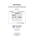
Sometimes there's a slight heat issue
problem with some boards. The second to the
last RF stage (Q405) may run a little too hot
during long transmissions. In this case you will
need to reduce the heat, but still provide
enough RF drive to the PA. The RF stage of
Q405's collector voltage is lowered a little by
adding a 27 ohm (1watt) resistor in series with
L413. (circled in the left image.) First, check
to see if the transistor gets hot before you do
this modification because you will loose about
¼ db output on some boards which could be a
consideration.
This equipment is old and subject to wear. The
(floppy) RF output coax is no exception.
During normal mobile use, plus modification
handling can cause most or the entire wire
shield to break off which would cause level
and interference problems. The coax is just
long enough to reach the filter it plugs into so
cutting it is not an option.
If this is the case with your board, remove the
broken parts of the coax and board's eyelets.
With a new piece of shield from a spare piece
of coax and solder-wrap around the damaged
shield to extend it to a point it can be soldered
back to the board as shown here; a repaired
shield on the coax output. Also, the "shorty"
RCA plug's ground fingers get loose over time.
It's a good idea to press all four in slightly for a
tight fit on the filter module. Be careful not to
slip and bend them in too far, when doing this.
Now, you can install the exciter board in the chassis as show here. Then do the wiring for the power
control board-3 wires, ground, A+ and control voltage. The latter connects to the PA control transistor. In
this view a feed-though cap was used however, OEM just has the wire go through a hole in the chassis.
Above view is the top of the chassis.
9
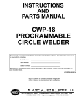
The picture above is before the exciter is installed. Did
you notice the two silver “boxes”? They are filters for
the transmitter. The one on the left is a band pass filter
(Z501) for the exciter board’s output. The one on the
right is a harmonic filter (Z502) on the output of the PA
section. Z502 is not tunable but should be broad
enough to make it to the top end of the amateur 2meter band. Z501 is narrower in range and may need
tuning. The image shows a “L” written on them,
indicating they both are the low range thus, don’t need
anything done for operating in the entire 2-meter
amateur band of 144~148 MHz.
Z501 comes in two band ranges. Model TFD6111 is
the (L) 132~150.8Mhz range and the TFD6112 is the
(M,H) 150.8~174 range.
If you have the M range it will need tuning which can
be done only while the cover is in place. However, you
can modify the cover by drilling 5 holes. Keep them
small to not affect the properties but enough to get a
slim tuning tool inside. 3/32” is suggested. Take care
to line up the holes right over the coil forms. Then reassemble and install the filter for tuning. Be aware that
some filters were built in the factory with excessive
sealer and may have to be discarded for another one.
The completed filter should look like the image on the
left.
The filter output appears not to be 50 ohms. It’s best
to tune the filter with a spectrum analyzer however;
peaking it with a power meter works in most cases.
For final tuning this filter needs to be in the OEM circuit arraignment (driving the PA) and observing the
RF level at transmitter output port.
10
The next area of discussion is the PA (high power) section. OEM specification for intermittent duty is
+50dbm however, for repeater use this should be lowered by 2 db (at least). For repeater use, besides
dropping the rated power a few db, fan cooling is also necessary, especially for the mobile type of
transmitter (more on this later).
Running the fan 24/7 wears it out. A better choice is have it come on only when
needed. This is done with a thermo switch; normally open, then closes at 100° F.
For redundancy, two of these switches are mounted, in parallel. Use a good layer
of heat sink compound under each switch.
As shown in the left image you can (optionally) countersink the screw head into
the radio’s heat sink. This is also handy if the screws you have on hand are a little
too short. Also you’ll need to make two notches for the PA shield to clear the
screw heads.
The last area of discussion is the RF output section. An interface plate had to be
built to mount the connector and give more shielding on that end of the chassis.
Steel plates were chosen and several being built as shown here for the connector.
The 8 holes will be 7/64 and the one center 5/8”. In the event the holes don’t line
up perfectly you can enlarge the small ones with a 1/8” bit.
The (old) OEM coax with a RCA connector at one end was used to plug into
the power control board. The other end was cut off and prepped for
soldering directly onto the new N connector. Shown here is the completed
subassembly (back and front) ready for the radio.
11
Now mount the subassembly to the radio’s chassis. There are four 4-40 type holes already there for this.
The 1/2” screws are too long, so either cut them, use washers or find 3/8” ones.
Shown below is the completed task for the antenna port.
Without any of the front panel being built, this may be a good time to run the transmitter though its paces
to look for any problems overlooked. In an extreme (bad) case you could stop here and start building a
new one. Just clip the needed wires for power/control and put a load on the RF port, etc.
Mechanical:
The mechanical part of the project is working with the panel, drilling, mounting the standoffs and fastening
with screws and bolts. Most of the bolts are 8-32 with phillips head. Phillips head (and pan head) make it
much easier to work with, especially in an angle, such as securing inside a cabinet. Even the terminal
blocks, TB-1 and TB-2 have these types of screws to hold the wires and lugs.
TB-1 is Cinch-Jones "140" series size; .375" in holes, using a 6-32 machine screw. Molex brand has the
equivalent in the phillips screws. Mouser part # 538-38770-0110 for the 10-terminal. For the wires crimp
them with #6 spade lug for 22-18 gauge wire, part # 517-2232.
For the PA power, TB-2 is also available from the same vender, "142" series size; .563" holes, using 8-32
machine screws. Part # 538-38211-0102 for the 2-terminal, rated at 30-amps. For the wires you can crimp
them with #8 spade lug for 12-10 gauge wire, part # BS-33-8. For best (high current) contact area, use full
rings instead, for 12-10 gauge wire, part # 517-1217. In any case, the Author prefers to crimp, then solder
all lugs.
12
PA heat:
For high duty cycle the PA gets very hot. The OEM 15v supply contributes to the problem. A solution is
running the PA at a lower voltage with the KPS-20 supply. Setting the power out to +48 dbm will draw 16
about amps from this supply. This and installing a fan control unit (FCU) keeps the heat problem under
control. Documentation on both these items can be found on SRG’s web site. With this arraignment,
typical time for heat-up to signal the fan is 6 minutes, while cool-down to turn the fan off is 14 minutes
(with the 100°F switches). Shown here is the completed project with labeling on the front panel; serial
number 4, ready for service.
Tuning and checkout:
Install the appropriate channel element for your frequency. The formula is carrier frequency divided by 12
for the crystal frequency (inside the channel element). You might consider sending the entire channel
element for crystallization so it can be compensated as well. Doing this also has the advantage of the
crystal company being responsible for the proper formula; all you need to supply is the carrier frequency
for the model of this radio. Next, tune the exciter board as usual per the service manual. In the event its
not available you can use the following procedure (running the PA voltage at 10):
The meter socket pins 1~7 are functional either with a stock test set or a simple meter. If using the latter,
typical voltages are as follows (when properly tuned): (a RS22-204C meter was used for tuning).
Pin 1 is IDC-audio level (no tuning here).
Pin 2 is channel element output; typical + .865v (no tuning here).
Pin 3 is the pulse amplifier output of Q402; peak L401 and L402. Typical voltage is -1.877v.
Pin 4 is Q403 output, or Q404 input; peak L403, L404. Typical voltage is -1.174.
Pin 5 is Q404 output, or Q405 input; peak L405, L406. Typical voltage is -.529v.
Pin 6 & 7 is ground.
Peak L407, L408 for power out using a power meter or spec analyzer. Minimum level is a +26 dbm to
properly drive the P.A. section. Typical level is +28.451 dbm (700 mW for math challenged folks).
On the power control board turn R611 fully CCW (min resistance). R610 will be your power control
setting. For transmitter output levels, (intermittent duty) rating is +50dbm (100w), +49.5 is 89.13w, +49 is
79.43w, +48.5 is 70.8w and +48 is 63.1w. As you can see “watts” change is overrated when rating it with
log.
Parts Listing:
For front panel & chassis:
1 Panel, 19” rack type, Bud radio: PA-1102-WH
16 Screws, 8-32 x 1/2” for mounting the panel to the chassis
8 standoffs, 1”, 8-32 thread, female-female, All Elect: SP-284 (.35 each) for the panel mount
1 terminal block, “140” size, 10-position. Mouser Elect: 538-38770-0110 (TB1)
4 Screws, 6-32 x ½” for TB1
4 Nuts, 6-32 for above
1 terminal block, “142” size, 2-position. Mouser Elect: 538-38211-0102 (TB2)
4 Screws, 10-32 x ¾” for TB2
4 Nuts, 10-32 for TB2
13
2 Switchs, SPDT, miniature, Mouser 10TC320 (DPDT okay).
1 Switch, DPDT, miniature, Mouser 108-0010-EVX (or use this number for all three switches)
1 Jack, 4-pin, Hosfelt Elect: 4PMCS (for panel mic jack) (or MCM electronics 27-7977)
1 Fuse holder, 3AG, All Elect: FHPM-31 (or Mouser 576-03420004H)
3 LED, green defused, T1 ¾
(for power indicators)
2 LED, red defused, T1 ¾
(for PTT, keyed v, indication)
1 LED, red defused, blinking, T1 ¾
(for PTT lock-on indication)
1 LED, yellow defused, T1 ¾
(for fuse indication)
7 Resistors, 1K (for the LEDs) (one is mounted in the PA section)
1 Pin jack, black
For the 9.6v regulator:
1 IC, regulator, LM7810, 220 case
1 Capacitor, tantalum, .22uf, 25v (mylar substitute is ok)
1 Capacitor, electrolytic, 4.7uf, 25v
1 Diode, common rectifier type, 1 amp, 100 piv (for the 6/10 voltage drop from the regulator)
For the 9.6v switch (keyed 9.6v)
1 Transistor, TIP 42, 220 case
1 Resistor, 2.2K, ¼ watt 10 % (2.7K okay)
1 Resistor, 1 K, ¼ watt 10 %
1 Diode, 1N4148/914 type (to isolate the internal 9.6v reference to the outside (12v) PTT equipment)
For the PA section:
2 Switchs, thermo. type, normally open, closes at 100° F, Mouser # 802-STC-100
4 Screws 4-40 x 1/2” (for thermo. switch)
4 Nuts, 4-40
(for thermo. switch)
Some heat sink compound for the switches
For the ground buss:
1 6-32 x 3/8” screw (longer ok, if you use many lugs)
2 lugs, #6 ring for AWG 14-16 (more lugs if you wish more ground wires)
For the antenna port:
1 RF connector, N type, female, chassis (4 hole flange) Ampenol “RFX”
1 Coax jumper, teflon type, 50 ohms (from OEM power control board)
1 steel plate gu 16-18, 2 x 2”. (8 7/64” and one 5/8” holes to be drilled)
4 4-40 x 1/4”screws to mount the connector to the plate
4 4-40 nuts for above
4 4-40 x 3/8” to mount the plate to the chassis
For the modulation section (channel element pin 4)
2 Capacitors, tantalum, 4.7uf, 25v (2-freq operation)
Mouser Elec part # 80-T354C475K025AT
Other needs:
Shop with tools and test equipment, well lighted; 40 hours typical time for this project
Glue; hot and epoxy (for holding LEDs, wires, etc in place on chassis & panel)
Labeling tape or Marker (for labeling the front panel)
Misc., wire, AWG 20, 22, or 24; black, brown, red, orange, yellow, green, violet and other colors as
needed and a few lugs. Some solid for board jumpers (CAT-5 orange wire is good).
This may be copied in complete form only for non-profit purposes, such as for the knowledge for the amateur radio service, with AK2O credited as
designer. For other arrangements please contact the author. Copyright: AK2O 2006, updated 8-29-13, 2-23-14, 4-19-14, 4-20-14, 4-21-14, 4-23-14, 64-14,6-5-14 6-11-14, 6-12-14, 6-15-14, 6-16-14,6-17-14.
14