1
SPIND1.E
TYPE
I
DRIVE
CONTROLLER
FR-SX
MAlNTENANCE
MANUAL
- CONTE!!l-S -
CZ-(a2TER 1 GENERAL
PurposeofzheSewice Manual . . . . . . . . . . . . . . . . . . . . . . . . . . . . . . . . . . . . . . . . . . . . .
1
1.2 Safev precautions and servicing personnel . . . . . . . . . . . . . . . . . . . . . . . . . . . . . . . . . . . .
1
1 . 3 Storing . . . . . . . . . . . . . . . . . . . . . . . . . . . . . . . . . . . . . . . . . . . . . . . . . . . . . . . . . . . . . . .
1
1.1
CHAPTER 2 SPECI FiCAilONS
2.1
2
AC spindle motor . . . . . . . . . . . . . . . . . . . . . . . . . . . . . . . . . . . . . . . . . . . . . . . . . . . . . . .
22 AC spindle controller ....................................................
4
23 Controller unit composition ...............................................
7
2.4 Extenral wiring. ........................................................
9
25
Pans arrangement . . . . . . . . . . . . . . . . . . . . . . . . . . . . . . . . . . . . . . . . . . . . . . . . . . . . . . .
it
*
CHAPTER 3 OPERATlON AND SETTlNG UP
3.7 Preparation for operation .
3L2
.
.
. . I . . . . . . . . . . . . . . . . . . . . . . . . . . . . . . . . . . . . . . . . . . . 14
Tumingonthepowar....................................................
14
3.3 Adjustment . . . . . . . . . . .I. . . . . . . . . . . . . . . . . . . . . . . . . . . . . . . . . . . . . . . . . . . . . . . .
15
3 . 4 stamp opemion . . . . . . . . . . . . . . . . . . . . . . . . . . . . . . . . . . . . . . . . . . . . . . . . . . . . . . .
15
3.5 Spindle orientation adjustment procedure
. . . . . . . . . . . . . . . . . . . . . . . . . . . . . . . . . . . . 16
CHAPTER 4 PERlODlC MAINTENANCE
4.1
Chdcing the cuntrolief unit . . . . ..o........................................ 18
42 Checking the motOr . . . . . . . . . . . . . . . . . . . ..~..........~.................... 78
CHAPTER 5 CHECKING THE CARDS
{Lists of LEDs, DIP switch=, check pins, variable -1
51
SX-CPUO, C?U7 cards . . . . . . . . . . . . . . . . . . . . . . . . . . . . . . . . . . . . . . . . . . . . . . . . . . . 20
52 sx-CPu2%lrd’ . . . . . . . . . . . . . . . . . . . . . . . . . . . . . . . . . . . . . . . . . . . . . . . . . . . . . . . . . .
‘29
5.3 sx-101 card . . . . . . . . . . . . . . . . . . . . . . . . . . . . . . . . . . . . . . . . . . . . . . . . . . . . . . . . . . . 39
6.4 SX-PW card . . . . . . . . . . . . . . . . . . . . . . . . . . . . . . . . . . . . . . . . . . . . . . . . . . . . . . . . . . . 47
6.5 SX-AJleard . . . . . . . . . . . . . . . . . . . . . . . . . . . . . . . . . . . . . . . . . . . . . . . . . . . . . . . . . . . . . 50
CHAPTER 6 SP!NDLE ORlENT POSlllON DETECTOR lNSTALLAl=lON P R O C E D U R E
6.1
Magnetic sensor singbpoint orientzrtion
6.1 .I Printiple . . . . . . . . . . . . . . . . . . . . . . . . . . . . . . . . . . . . . . . . . . . . . . . . . . . . . . . . . a
:. .
6 . 1 2 Time&arc . . . . . . . . . . . . . . . . . . . . . . . . . . . . . . . . . . . . . . . . . . . . . . . . . . . . . . . 53
6.13 Oirection of installation of magnet and sensor . . . . . . . . . . . . . . . . . . . . . . . . . . . . SJ
6.1.4 Gutions on installation of magnet . . . . . . . . . . . . . . . . . . . . . . . . . . . . ..fl...... 56
6.1.5 Czurions on installation of sensor ...................................... 56
6.7.6 Overail view of magneric sensor . . . . . . . . . . . . . . . . . . . . . . . . . . . . . . . . . . . . . . . 56
,
62
.
Encoder zypc multi-point orientation
6.21 Principle . . . . . . . . . . . . . . . . . . . . . . . . . . . . . . . . . .
*
_
. . . . . .C.:_:TLY.‘, . LI’_^‘55-- C
. . . . __
..... 60
6z &&a type muki-poim oriamacion system composition . . . . . -_ . .--‘ . .__
-__6.2.3 Overall view of enwdcr . . . . . . . . . . . . . . . . . . . . . . . . . . . . . . . . . .._..........
_ ---_.-._ _ . _ 61
__ _. .
CHAPTER 7 TROU8LESHOOT1NG
.- __ _-__. . .
---s-2---_--__
7.1 Preliminary c&Acing . . . . . . . . . . . . . . . . . . . . . . . . . . . . . . . . . . . . ._. . . . . . . . . . ._ . .. . -_. .
.7 2 1st mp troubleshooting . . . . . . . . . . . . . . . . . . . . . . . . . . . . . . . . . . . . . . ..--VI- 6z__ _,_ ._L
. . .-.__
. . . . . . . . _. ._. _ ..-._ _64
7.3 2nd racp aoubleshooting’ . . . . . . . . . . . . . . . . . . . . . . . . . . . . . . . . _ _ --.-_ ____.___
~’
.
7.4 Detaiied chcking for each trouble . . . . . . . . ..*.......................-..c....
.-__ ._-_
__::
-_ _ -. _ _ _ _._ I
CHAPTER 8 REPLACEMENT OF PAdTS
_--.
................. 7 9
. . . . . . . . . . . . . . . . . . . . . . . . . . . . . . . -.-____,_.
fap~aoftacircard
_._ . .._
;.- _ ._
m*
_.
.
.
.
.
.
.
.
.
.
.
.
.
.
.
.
.
.
.
.
.
.
.
c
C....
.-._..CC.L..
8.2 Tyristor module and tnnshtor moduia
-..-.~..~-........ 81
8.3 Speed danclot and shaft coupling . . . . . . . . . . . . . . . . . . . . . . . . . . __
__
a-.-__
______. -Jr87
_
8.4 Cooiing fan . . . . . . . . . . . . . . . . . . . . . . . . . . . . . . . . . . . . . . . . . . . . . ..*............
_
: ._
.:
.
.
.
.
.
.
..*.....................................’....._..___c-~-----8.6 Bearings
-:=-____. __, .._
__;
- - CHAPTER 9 PARTS LIST . . . . . . . . . . ..r.............*..................~....
- -__
db_.87
---._-_--____--_-.-- . ._
_-
^
I..
.
--__--__
.
__-__
._
_
__-. .-.
_
-e--w
e---,-m
.-.-
-
___
_
._
.._.
__-
_-----m-_---
- ._.--i
._
---.----- - - .__.
-.
‘~
----.--B-w
_I
-_
.--
,_
2.
.
-
d-e.
-._-_-_-.-
-
--.- -____. __
.)-._.___
--- ~.. - -_ - _-
_
._
_--__.__- -
--
--
. .
.
~-
_~
~
-.-._-
_
___
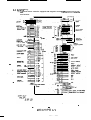
C H A P T E R 1 GENEilAL
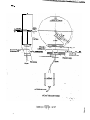
1.1
Purpose of the Service Manual
FR-SX Series is a line of AC spindle motor speed convol units (inverter) of regenerative
braking type.
This Service Nlanual mainly destribes periodic maintenanca and troubieshooting practices
tiat are very important for truublcfrae, long use of your FR-SX.
Please read this Service IManual carefully until you make yourself famiiiar with the servicing
paxics of the unit.
1 2 Safety precautions and senricing panonnei
The following cautions are very impdrtam to assure safety in maintenanca work.
- The unit should be SfMcd, maimained and checked by qualified penon. It is vvy hazardous that a person having no elcnrical knowiedge handles the unit.
- Befom the unit under live condition is handled, remove finger ring, wrist watch. tiepin
and other metallic objects from the body.
- It should be born in mind that eiecnic shock might result in death.
Care should be taken to the fact that some parts of the unit am at high voltage no matter
whether the powu~ source ilself is ground or not.
When any testing apparatus is applied to the unit, the t&ng person shoiid not touch any
grounded metallic pah Since test apparaus or equipmcm is usually not grounded and
test apparaus is at high voiw a@nst the ground, care shouid be taken not to touch a
grounded part when the unit are opemted at adjustment or remedy.
- Do nut wear loose cioths that might be involved in mtzcing or movable parts when gaining access to rotating or moving parb of unit
- Do not remove or install a card whiie the unit is fed with power supply or operated.
Otherwise the unit may be serioutfy damaged.
- Do not tuuch the unit immediately after the power is turned off, but wait for at least one
minute (time necarary for complete discharging of capacitors) before stating maintenance.
SOring
i
When the unit is not immedilrcfy installed and used, store it in a de&, dry placa at modefate temperatura using car8 not to allow amwing of moisture and dust in the unit
Moisture or dust involved in the unit may cause deterioration of insulation.
When the unit is left out of use for any length of time, ke the unit in the same conditions
as it is in operation. It is recommended, depending on the condition in the storing place,
to use a space heater.
-.
_ .
___ - _ __ _ : -_ _ ___ -.
_.._-- ._ _ -L
C
_.H APTER
2 SPEClFIUTlONS
__
__
1
____--
I
.
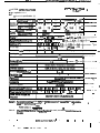
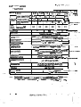
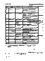
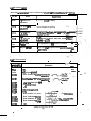
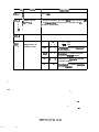
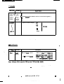
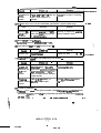
2.1 AC spindle motor
(1) Standard specification (I)
,
-me-
/ Gsttinuous rating (kW) /
gz& f 30 min. rating (kW)
50% ED rating (kW)
St=+
Bare
wead ( R P M )
I
1
5.5
1
7.5
1
11 -- ( 15 I-_ l&i.
5.5
1
7.5
(
11
i
15 --. )
11
115
15.517.5)
1500
I
Muc speed (RPM)
Frama No.
Rated
1
3.7
torque kod (kg-m)
1
All2
2 4
GD’ (kgm')
1
0.07
Weight (kg)
I
65
Permissible radiai load (kg)
150
1 3.57 1
175
:
:
-
I
i
1 7.1&-ax+-w+
1 0.2~&a35-.J-~+---- y-
02
1 100 I
200
-_’
1
.~
4 . 8 7
1
0.093
1
1 : 22
____ ____a___- __-. -.
Il8.5--122
--f-u32-..I_-AGc&-----
8132
I
1
18.5
4508-
1 8112 1
,
__.-- .-
m. ____
I
6000-1
1I
-
115
l
.I - 7-30 I
190
300 ..
I’
-
I
Cooling fan (W)
I
Vibration
M
I
Noise (dEf (A)
Ambient tmnpararrra
.
r C)
Insuiatiolldarr
vto
1
__c ___-__~____.._1 .-_.-_-.,___ .-
O-40
I
.__ __--. - w-...
F
Paint color
mmll
.N55 _.___.~- _ _____ -.-------
Pulse gmerator, overheat detector
Accusodes
J&C4004
Cmuoilar modal FR-SX-2-
Powersourca
_ __-_-__ -~
.
Standard applied
55K’
rqhment (kVA1
7.5K
9
12
1lK
’
18.6K
_.
23.
22K
.._.._
2s
__
.---.
.
Nate 1:
For spasd larger dun 4,500 rpnt, the anput (cqxcity) is reducad to the value cab
:. ?
latzd with the foibwing formula:
.
Nate 2:
When power source utherthan specifiad above is used, a suitable aansform& huld
bused.
B=2L735-S5 N/2 .
.
-
-_
_-__
-
l
.
.
._
._
-. -
2w~23ov*10%, 50/60Hzs%
.
_
__
15K
17
-- =Y
.
-.
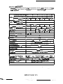
(2) Standard specifkation ( 11)
When be Standard Specification (I) is not applicable because speed reduction ratio tiar
meets 1,6W rpm base speed is not avaiiable, this Standard Spacificacion (1 f I may be adapted.
I 50% ED adng (kW)
speed
7.5
5.5
I
I1
15
I Base swed (RPM)
1150
Max. steed (RPM)
4600
Frame No.
I
Rated torque (cant) (kg-m)
1
67 12
8732
3.13
4.66
1
Cl32
1
6.35
GO2 (lcg.m’)
0.093
03
025 i
Weight (kg)
75
100
115
Permissible radial load (kg)
200
Cooling fan (WI
18.5
(
1
0.35
130
Al60
9.32
(
22
1
8160
1 12.7 1 15.7
0.5
f 0.83
790
245
300
35
I
I Vibration
1 Noise (d8) (A)
I
I lndlation
I Overhad wwcity
I
72
n
I
Output shaft horizoinal or downward
I
120% of 30 min. raring, for one minute
O-40
Ambiem temperzun, (‘Cl
F
insukttion c!ass
‘Paint
color
-._.-_.
. .
Munsell N5.5
ACZXSkieS
Pulsbgmetxtor,ow+watdetector
I ConuoI ler model
1 Pwuersourca
I
F R-SX-2-
requirement
1
(kVA) 1
Power source voltam and
frecwnw
llK
65K
9
1
12
l5K
1 t? 1 P 1 26 I
200/2c0-43ov*10%, 5il/6OHz53%
I
22K
I
-_
I
z-
__-
__I‘
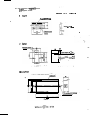
2.2 AC spindle cr~nuollef
(1) SQeciflcatian
_
I
lS~~+?ZK i_____,
._
__, 15
i
18.5
/ 22 I__.
I
I
I
i
Model F R-SX-2Outputcaxaciry
~50~~0
’
output
5.5K
I
1
7.5K
(kW) 1 5.5 1
I~utput~umnt(A)
I
43
!
Powrequirement
(kVAI
I
j
7.5
1lK
74
1 55 1
/
]
1 11
)
_
I
100
-.
-__
-7.
_-.
I
1
125
_
_ _
j 148 1
1
9
p____-28___ ‘_ s___ --.---,
_..__
t :
t_
1.
. . __-
12
_
Heat walue (WI
r-
42
Wdsht (kg)
L
-xI.
_t- ---Y-_=---
.----.
_-_-
-
7hnsittorsine-wave PWM iinrsrthr
Main circuit
Speed feedback wntml with pulse gemmtac_dig
Conapl circuit
.wnuol
loop control, optimized F-V paam
_
~rrghn~,,,~~b+&rig:
Braking method
_
.
speed amuol range
speed
55
Le5s than 02% of maximirins+ed
_
bith lord changing within a ange from 10% to 100%)
reguiation
. -
Digital command, binary 12 bit3 or 8CD 2 die &&g~~d,+f~~ _ _-__--I___ .-__. ._._I_ (Input impedance: approx 10 -Kahmst
Slip c&?trol acce!eration/decelemtion . .
Dime limit ac&Jduxl.: 0.5
_.,_ -- 10
- se&
__. _ -
ACChdOn/
c
I
dacderationmethod
-SW --___I
Ambiant tempaaarrd
humidity
Gnfironmentai
~vibtatiosi
L&StkUlO.5G
I Standard appiied
I Cooling .Now:
1\
I
Tobefreefromdeuimentalgasanddust
(To amform with lEMl103, Grade “C’I
condition
.
_.
I
I
IEC
.._---. -- -.-__+._-__ _-
Fan
**
-
Incorporated DIP switch is used ~select digital spcad aznmand beween “binar/ 12 bits’
and “X0 2 digid’ and examqi signal is used to s&et analog speed__..command.
_..____
.
;.:
.
_
.
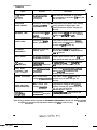
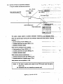
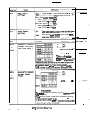
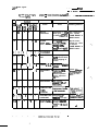
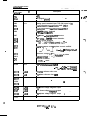
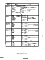
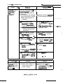
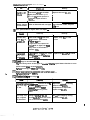
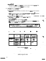
(2) Pmtective functions
I
Name
DVER HEAT
IMOTOR)
EXCESSIVE
SPEED ERROR
Function
Overtoad/overheat
pmtection
Description
I When motor is overloaded, or overheats
due to standstill of fan motor, tie base and
gate are shut off.
.
Prevention of too large ’ If commanded speed differs From actually
] speed COITUOl dnOr
i running speed to a degree larger than
’ specified tolerance, the base and gate are
shut off.
BREAKER TRIP
Short-circulating pmtection
Grounding protection
If large current ff ows in the main cirwit,
the base and gate M shut off.
PHASE LOSS
Preventing of singtephase operation
If any phase of power source is disconnested at the time the power is turned on,
the base and gte are shut off.
EXTERNAL
EMERGENCY
Emergency stop with
external signal
OVER SPEED
Overspeedprotection
If motor speed exceeds 115% of tfie maximum speed, the base and gate are shut off.
IOC TRIP
(CONVERTER)
Iratamaneous
ovemumm protection
If overcurrw\t flo~la in the converrer, the
base and gate are shut off. ’
OVER HEAT
(CONTFQLLER)
Main cirtait ohioad
pmtection
If main circuit semiconductor overhea?~
due to overload or standstill of fan,
the base and gate are shut off.
UNDER VOLTAGE
Main circuit source
voltage drop pmtection
If the source voltage drops below the
specified level, the base and gate are
shut off.
OVER VOLTAGE
(REGENERATION)
Main circuit overvoltage pmtE?&on
If regenerative voltage at main cimuit
capacitor exceeds the specified level, the
baseandgatearesiwtoff.
IOC TRIP
(INVERTER)
Instantaneous
overcurrem protection
If ovenzumstt flows in the invener, the
base and gate are shut off.
With emergency stop signal given by
external device, motor is stopped and the
.baseb shutoff.
..1
Note: If any protective means (except for EXTERNAL EMERGENCY) works, the base (invertar)
and gate (convemr) are shut off and the motor stops stir inertia running.
.
.
.
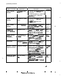
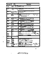
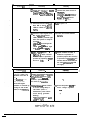
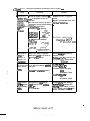
(3) Auxiliary functions
Name of function
LOAD METER
SIGNAL
Application
!
1 Connected to load
meter
I
Description
I
I
An one-way swing DC7 mA meter
i
is connected.
Full scale corresponds to 150% load 1
(adjustabie within a range from
100% to 150%).
SPEED METER
SIGNAL
Connected to speed
meter
An one-way swing DClmA meter
is connected.
Full swle corresponds to the
maximum speed.
ZERO SPEED
SIGNAL
Machine innriock
Signal ‘for conlacs that ciose when
motor speed d- below 50
or ZOklOrpm;
Contacts
o p e n
emitter
THESHOLD
SPEED SINGAL
Response to NC
Output transistor tums on witi this
signal when speed reaches within
arangeof~15%ofpnsetspeed
Open
emitter
For prevention of
The output tmnsistor turns on with
this signal when siippage excds
Open
emiuer
LOAD DETECT
SlGNAL
ptunging of cutter
the specified vaiue (110%) near
th limit value (120% outpud.
(CURRENT)
OVERRIDE
For override in
automatic optracion
Ovwide setting range: 50 - 120%
Override can be reset by opening
controller terminal DEP.
SPINDLE ORIENT
(Optional function)
Indexing of spindle
Magnetic sensor type singh+point
indexing and encoder type multipoint indexing are pakble.
Contac5
OPafJ
With orientation start signals
(ORCMI, ORCW1, m command
signal, complexion signal and orientzftion wmpietion signal are output
TORQUE LlMlT
For gear shifting,
When geraring is shifted, spi?dle
Open
etc
motw is fun with a temporariiy
emitter
reduced twque.
This funczion is used when torque
b limited.
. i
.
.
.
’ BCN-21735~SS
.
N/6
.
.
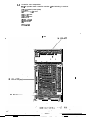
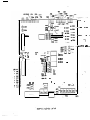
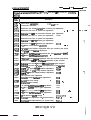
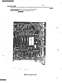
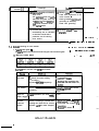
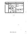
23
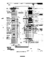
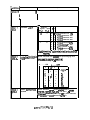
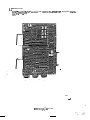
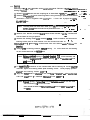
Controller unit composition
T’ne AC spindle motor controller consists of the following 7 sections.
(1) Front panel (name plate)
(21 SX-C?U (1, 2) cards
(31 sx-IO1 card
(4) sx-PM/ card
(5) SX-AJlcard
(6) Converter
(7) lnvertei
_ . ..-
.
1
-z r _
_
__1_ __--_- ;_
__ ._
_
:
_-
-_
.-_.
.-- -. _
_.
-_
--
---_ -.. _.
v
-
--
-_
-.-
-a
’
.--
v- -
_
-4.-
we.-
__
a----.---.- =-
_-.
--- -
--.
--_ :
-G-
-_._. .
- .
_L-
I
-.-__
-- -_-
-?-_
--_
- _
_- __ __ _-.
--_
-_ __.
--.
--
_-- --
. ._
---- __.
-.
_-.
_- ._.
_.
-_L
.>.-
3
P. .-.
;-
_-
-.
L-_..
-_--
_-
--
._
-_
-._
-I
___
-
-
-
--
_
.
-
-_
------ -
.
BCX--2L?3544=
-
.
.
-c
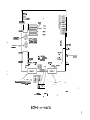
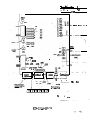
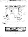
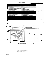
24
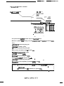
Extefnai wiring
(1) AC spindle motor controller equipped with magnetic sensor type signaie+oint orientation function.
i
I
I
.
.
_.
.
aCw21735-sS N/9
.
.
(2) AC spindle motor conuo~ier equipped wirh encoder ryptw%&iykm-.___
tion.
.
_ -
.
gg’i
x2:1
Zf_l
oamraaz~1--;;;rirrt-.
_ .-___
*
*
fqd,
gY-&..Llm!
*. _m
m fl IT.1
I-
_
. ._
_.--_____---._
..__-_
.._ _. __.___
--. .
-:
.
:
.
.
.
mmlrRpln
nns*tr;
cortcuy
DC
. .
2wo.i.q
AC *Cf
_’
&a&
- --.-
BC+23?35-S5 N/m
._
- __-_;--
.--- -
_. ..-.2.5 Pam arrangement
-._ .
r
-
:.
_
‘/- /
-
__
_
--
..
,I
BCZ+21733-SS N/l1
.
.
__
--. _ _.
.-*I- -
__ _i_
-In-
______
--
. .q. -:1:
QII
3;
:--Q
-’
--:_..
__
_-.-_
_.._
__
__
__
.
___
1
_
.:
-.__
.-
.
-_
BC%1?35--SS
.
.
.
a/12
.’
-.
.
.
-
-_
-_-
.
_.
)
_.
_
I
- .-. :--.;-_
^_ _ __
_
.;_
;-
CHAPTER 3 OPERATION AND S67TlNG UP
.____
_
_-=-v
L_
.
-_
_f
,I
e-e
-
-
__
_:
Preparation for operaion
When tfie AC spindle motor comroibr is fed with tie Power s0ufCe for ti?e first time, the
following checking shouid be made.
___.
:
(1) Has externai wiring been completed in accordance with tie wiring diagram?
(2) Are the motor and controller unit propdy grounded?
- . .
(31 Are shielding wire ends broperb connected?
- They should be connected to shielding terminals.
- They should be wnneczed without looping.
(4) Are ail components not damaged, and securely installed?
(5) Is any foreign matter such g wire chip involved in tie unit?
(61 Does bacfi card present good appearance?
(71 Does ROM No. conform with the order sheet?
‘I)
Da DIP switch settings conform with the order sheet?
32 Turning on the power
When the checking has bean ampleted. feed the controiler unit with the power sourcs as
(t ) Turn on the poGr.
122) Make sum no alarm indication LED (LEDt& 13, 14 and 15) on the controller front
pmddcmnotligtrt
(3) Make sum s~tus indiacion LEDs (LED2 “READY” ard LED70 “ Z E R O S P E E D ” )
.
light
- _
Now 7910 conuoller is nsady for opedon.
c
Althouah thu mvw3r cabie can be connected to the contmllar without noting the phase
connection. tiase seuuance can be dmdced tttroud~ LED1 “Pf-lASE SEQUENCE”.
‘LED1 liotm~them~cabiaisconnecWincorrectpbesequam#
.
3.3
Ad jUSnnMt
(I ) Speed meter calibration VRI and load-meter calibration VR2
When speed ,neter it connectEd to the spindle
inverter, turn and set tie V R 1 so ihar
the weed meter reads the maximum speed with DIP witches SW1 - j
set at OFF.
Also adjust the load meter to 120% by serting the V R2.
When the two variable resistors have been set, set SW1 - S
to ON and set the RESET
switch (ST1) to ON.
Since other variable resistors have been factory-adjusted, do not dinufb these settings.
(2) DIP switc??es and setting piru
Check that DIP swi&s and setting pins are set properfy as specified in the other
stlcee
If not, correct setting,
When setting is changed, be sure to operatt the RESET switch (STY) to ON.
When spindle indexing (stop) position must be &anged, change the sertings of DIP
switcha and setting pins for individual machine.
For ting procedure, refer to pan. 3.5.
3 4 Stwa~p opeaion kwmmodation)
Connecz the motor shaft with&e machine shaft and ~&MT &e&on to check the =nuoiler
unit for condition.
i’
Then exert ioed oAae mOtw and check the following items:
- Unusual sound
- Unusual odor
- Bearing temperaturn
l .
_.
BC+21735-S3
II/13
.
(2) Encder wpe spindle orientation
USW~ operation soed RPM
80- 155 rum
A_
i 2nd oosirionina Iof
sw2-ISI6
0 0
Low
p 0
i
i
I
Ia
High
.
7
0
x
:
3
gain
ON
i( X i
The speed change parcem a spindle stop is as illwtrazed above.
When the spindle stops running over the predetemked stop position (indexing posidon).....
- Deereas 1st positioning loop gain.
i bcrease orientation speed.
- Decrease 2nd positioning loop gain.
When shorter orientation time is desired.. . . .
- lncrmtse Tstpositioning loop gain.
- lnuvsse orientation speed
- I- 2nd positioning loop gzin.
When huming oaus at spindle stop . . . . .
i
- Decrease 2nd positioning loop gain.
-.
Stop pcsition can be adjusted by operating SW& 9 and 10.
Notes: (1) The data of gearing ratio stored in the ROM sbuld meet the gearing
..*
citioinuse.
(2) Adjustment may vary depending on gearing mtiq._
.
CHAPTER 4 PERIODIC MAINTENANCE
‘_A_“=>
_
r
-
_
-z=_.
__:
,
._
L
‘__
_
^
_*
In order to assure the full performance and uoubie-free, long use of the ccrnwot+~
worthy makerlance is indispensable. Periorm the periodic maintenance as insrucred below. -
:=- ’ -
I:-‘-
4
Note:
.
Electric shock might result in &a&&
&for0 starting the maintenance, do not faii to make sure all power sources are
turned off.
.
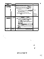
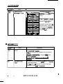
4.1
,
Checking the cwm0ller unit
Itmn
1. Cooling fan
2 Cteeniiness,
loosescrew
4. Wiring
Ff=PJsncV
Checkup
Monthly
(1) Does the fan rotate smoothly when
tumed by hand?
(2) Does the fan rotate powerfully when the
power is given?
(3) Doesunusual sound occur in bearing?
At suit-
Periodically dean each part and re&tten
inputkuqwt terminal scram and other
-.
abie in-
Evcry3
months
(1) Ircomactnotwornout?
At
Is any conductor in contact wittr the casing
(this may occur whei~ wire is pinched by
hinges)?
suit-
able in-
(2) Can miniauuw nlsy Jet work amzxzw
lin the main cirarit?
Replace de
fazive fan.
Replace defective relay.
L
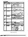
42 Checking the motor
Item
1. Noise,
vibration ,-
i,_-_
F=WsncY
M0lTdlly
Remedy
QMchP
o
Does unuwal sound or vi&on occur?
If u-l sound or vibration occurs, perform
* foilawing chscki?g:
(1) Check the foundation and installat+.
(21 oledc dignment of shak
(31 Check if vibration isaammittcd from
the machine wnnacEsd with the motor.
(4 zlgwi+i;
condition (if noise is
.
(51 Check if large noi$ or intensevibration
‘kcausai by speed reduction gears or
-.
drive belt
(61 Check rhe conaoller unit for condition_
(7) Check the cooling fan for condition.
’ ’
-
;
(8) Check beit tension.
..
.
.
I -
.
Frequency
kern
7 Tempera&C
ture rise
/
i
;
I
I/
I
I
Checkup
Monthly / o Is bearing temoerature not too high?
1
(Usual bearing temoerature: 110 - 40°C)
I
i o Is motor frame temoerature not too high?
(1) Check tnat the cooiing fan Nns in good
condition.
(2) Check if cooiing air passage (soace between
the motor fame and the cover) is clogged
with foreign matter.
(3) Check if load is excessively large.
(4) Check the controller unit for condition.
3. Insulation
resisranoe
Every 6
months
0 Is insulation rasirtance not too smaii?
4. Cooling
fan
Weekly,
monthly
0 Does the cooling fan rotate atisfactorily without generating unusual sound and vibration?
t Remedy
I
1
i
/
/
I
Clean.
’
Refer to
‘Trouble
shooting”.
- To check insulation resistance, disconnect
the motor from the controller unit and
measure resistance between the entire circuit and the ground using a mager.
(The insulation resistance should be larger
than 1 Megohms when measured with
5OOV megger)
If the insulation resistanar is smaller than 1
Megohms, dean the motor interior and dry.
To dry, breakdown the motor and place it
in an oven at a temperature not exceeding
.scpc.
:.
)
. i
BC.*21735’--SS
N/l9
.
CHAfTER 5 CRECKING THE C A R D S
___.:
_;.
- __-
Note: Since all
-.
-1.
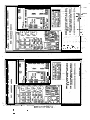
5.1 SXC?UOand CPUlcards
sx-cPuo**~ no 0rientat:on cad
sx-CPU1
l
_
--, _
_'.
.I
._
I. _ . _
- I
z_ +
_ I . . - .- -:-
* * Magnetic orimt&ion cad
_I___e__._-
-:
;:
__
.
_ _
_
-
-.
-
___
_
-
.--
..-
_I -
x---i’
-3
--
--
--Iv-
_-
_-
-
__
_
_.
-.
--
._-
1;.
c _=
- .;
-s_ _
.
---.--- ._ . .._- -_-.--_ _.
_.__ -_,._ . _.--. ____ -.- ._ __- - ---: _-..
_--____
.
-.
_ ..-_-- _-_ -. -
_ .-. _ -
_*
_
.- -‘I--7i
_. .-- --- .____ - _-
_ __ .-__ _-- - -- --__.__ __ .-- -----
- -.
. __ . _ _-.. _ __
-.--e-w.
--
.
.
’-!‘5A
0
DCA
OL
1
i
i
0 LED5
ON
RESFT
I$VU6
.SW6
CON 37
7
ORIENT TEE
CM3
l -
.
TO maintenance
hil68.
l
#WA
* CH65A
P-1
cl+64 . ai55
---.* ..
CM6
-m-
l
From orienmtion ‘patirim
.
detecting man8ricnnsor
_-
.
VR VR
3 I 4 I
;. .
___
_.
_
-y--a
‘.
_
._
BC?+2 17 3,&S N/21
.
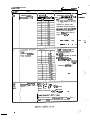
(I) List of LEDs
:;
Name
ED No. I
AD1
,EDZ
I
:.-_ _
Description
Application
Power source phase
PHASE
SEQUENCE
discrimination
READY
Reedy for option
CW ORIVE
CCW DRIVE
LED4
.:I
_ _-
Lights when power soum connektion is in
positiveqh2m sequence.
Does not light when power source connection is in negative-phase ~equertce.~~
l&ho when the wnuoller is ready for
oparstion.
Dam no% light whaT-sm_ input. of
OFF and emergency sop commart~~giv&
(baseandg8testlutoff).
LED3
.
_.
T
Motor Cw lutathl
Ligtws when momt CW rawion commend is
command
input, or when thespindleIZii3exed.
Motor CCUV rotation
Lights when motor-@ G&n coymx
-: - _
- _
is input
--:_ ‘- ^
_-
command
‘3 f
-_
_.
_L
-
L
_
_-.
SPEED
LED5
Speed demzion
Lights when mow speed decma&beioW ’
the speed preset by DIP.
Cu;rsmdet8crion
l&htstiencurrel7tlargsr~11o%of
&ted armm Ram in dw motor.
DETECTION
CURRENT
LED8
DETECTION
LED7
UP TO SPEED Threshold speed
L@awhenmotorspeedreechest15%of
commerldedspeu&
LED8
APPROACH
tion position
Lights when spindle enret orientation
(indexing) area
- -
InparitiOfl
Lighter when spindle smps within the ran&
ACCSStOOliama-
INPOSITION
LED9
p=byrottryswitc)l
LED10
Z E R O
SPEED -speed
LED11
: -
--!
:
Lights when spindle speed goes down below
!he’?ero”speedsetbyDIPmritchcr
0.
Natused.
Note: The invercw worlci sisfacmrily no mat&s whether its phase sequence is positive or
:. ?
.:
nagativc
. i
.
.
.
. .
.
B-2 I73 !i-SS N/22
.
_. -.- -._ -_ .--.----.--.
.
.
_-
Lin
of DIP switcnes
Description
Name
swl-9
j NORMAL’TEST
I
I
I
j
!
I
O N . . . . “NORMAL” (Usual operation)
OFF.. e ‘TET’ (Test operation)
In usual operarion, the switch is set as “NORMAL”
position.
When the circuit is checkad or spindle orientation is
checked, the switch is set at ‘7EST’ position.
SWl-2
CLOSE/OPEN
ON . . . . “CLOSE”
OFF . . . “OPEN”
Speed control loop OPEN/CLOSE c&rqeovcr.
Spaed detector function gr~ be checked by comparing
operating conditions when the switch is sat at “CLOSE”
and “OPEN”.
SW1 -3
BINARY/BCD
O N . . . . “BINARY”
OFF.. . “BCD”
Digital speed command mode can ba saiectad hy thL
switcfi.
Spaed command is mad ih binary 12-hit data with the
switch sat at ON, and in BCD 2digit data with the switch
#tatOFF.
‘.
,
SW14
AITENUATED
EXCITATION
EXCITATJQN”
O N . . . . “ATJENUATED
O F F . . . “NOT AITENUATED EXCITATION”
In usual opera&on, the switch is set at ON.
Wtth the switch set at ON, excitation voltage is decreased
for mduction of noisa (when siippage dacreasas).
METER CALlBRA-
ON.. . . “METER CAUBRAllOliS”
O F F . . . “USUAL OPERATlON”
SW1 -5
SW14
TlON
~isswitcfrisoptracdwhan~rnmratloadmcrcr’n
caiibmted.
With the switch set at ON, meter full-scale voltage is
output permitting calibration of mater.
:.t
_
.
.
._
BC?.?.21735-SS N/23
!
(PIN1 of SX-IO1 is set at l *i
When base speed is 1 SO0 rpm,
HIGH SPEED-6000 rpm
LOW SPEED - 4500 rpm
When base speed is ? 150 rpm,
HIGH SPEED = 4600 rpm
LOW SPEED * 3450 rpm
"HIGH SPEED"
goes down below 25 rpm.
Zero speed sigmd is ourput when spindle swe
,__--m
MAGNET C SENSOR
ORIENT POSITIONING LOOP GAIN 1
“!_
____-I_ _ __._
____ __ - -
_
Thiq switch funcrion is
effaxive only for magn
sanoor type oriantation
Tha standard switch sdng is "mode
0" and mode
_-___
of
---
Thisswitch function is effective only for n&rkic sen
typs orientation.
Time taken for speed change f&n “orientation speed’
. i
m’sewoconUulspctd”irset
If spindle stops running aver the predetermined pasidcm
.
BC13-2If35-SS
.
N/24
Name
iwitch INo. j
Description
/
W2-8,
I
.
j
I
/
I
I
7
svv3-lSW32
TORQUE LJMIT
1
External
signal
input
TLl
TL2
.O
X
X
0
1 2
0 0 ( Torque limited to 10%
0 0
Torque limited to 15%
Torque limited to 20%
x 0
x x
Torque limited to 25%
limited to 20%
iimited to 30%
limited to 40%
limited to 50%
.__. . .
The: S&$7 tirti~ is .ti char&d ~nlea’paiticular torque
limit is mquired
Sw3-3SW-5 -
0
0
x
x
Accrfcration heI& Speed command time constant for speed ranging from
TIME CONSTANT
zefospeedtomaucimumspeedissuL
Standard setting: t .5 s
0 . . . . ON
,
3
x....OFF
iO3S
0
0
0
0
0
x
1.5,
0
3:’
0
x
x
4’
X
0
0
5
x
!:
X
X
0
8:
iJ$
X
X
10
X
SPEED DETECTlON
RANGE
.
I
4 I 5
:Q.x
sw3-6-
Torque
Torque
Toque
Torque
0
x
0
x
‘0
Speed detection ange can be seated from 8 ran&s
(2%, lo%, 18%, 26%, 34%, 50% and 58%). -. *
When speed enters the speed range set by these switches,
the aamistor for speed detection tums on.
BC-W2 Lf3395 N/25
___.
ZwirehNa
_
_
___
_
.-_
Oescripdan
Name
sw3-6sw3-8
7
8t----
0
,1 ____..~.-
0
0
X
X
0
X
X
0
0
0
X
X
l--F=--
0
I
x __..__ -- -. _ ____p_.--X
50
SW4-1
SW-2 sw4-7
ipindle orientation speed and srvuca~~~t sp‘ced-arrser ----ry thee switches (geering ratio is &tanged for ihdividutil - -. _^ .-. ---_--__Ippiication)
GEAR RATIO
SETTING
SW48
SW51 SW52
lsotused.
DlREC7lON OF
ORIENTATION
1
.
.w
I
0 . . . ..ON
X .,...OFF
1 *
2
PRE
0
0
tiof ofmotor
CCU
0’
x
*.--_Ori- irreourKeFdockwise dims&on of motor
rotation_._ ..- _ _ __--__._______
au
X
0
X
c w
X
I
Orientation in forward direcrotation
Orientation in c!ockwise
diratxion of motor nnation
Orientation in h&wise
dimction of motor nxation
1
-.
..
..-
..
-.
. :
4
,’
List of rotary swtcnes
I
1 Switcfi N o .I
SA’6
Name
j ORIENTATION
: SPEED SETIING
1
!
I
i,
II
!! r
/j
!:
'I
/
,
I/
/
Description
Sming
/
0
,
I
1
2
:
/
, “Orientation Deed” for
magneric sensor rype orienta80rm1
tion is sat by this rotary
85
switch.
,!;
5
I
105
6
I
110
7
1
115
8
I
9
I
120
125
A
B
c
0
E
130
13s
I
I
140
145
Tne listed sperds are skndie
1 speed RPM and motor speed
' depends on gwring ratio.
’ Orientation speed should ba
decreased when spindle stops
running over the predetermined rtop position due to
large load GO’.
150
F
155
I
<
W-P __ -e-_-.-m
-
list of togggle switches
Swirch No.
Description
Name
RESET
7
For initiaiiring the inverter.
This switch should not be operated while the motor is
nmning..
Whenmt DIP NvitEh setting is changed, this switch
should be apeDO NOT RESti WHILE THE MOTOR 1s
RUNNING
The motor funs at “orientation speed” while this &itch
is held at ON position.
When r)rt switch is set to OFF, the motor stops after
completion of one cyde of orihazion.
.
.
Bcx-21735-s5
z/27
List of variable
msistom
Since the variabie resisron in this card have been pmperiy set by us, do nox dimrb the mtingt.
r
,
VR No.
Oescription
Name
VR16
“8” phase zero
adjustment
VRt3
“A” phase zero
adjustment
“A” phese gain
adjjscmult
00 not
change the setting.
ge
CH56, Speed feedback,
Sine weue PLG Puke generator)._ ____
VR15
“8” phase gain
adjustment
VR3
Pusition shift
Fine adjustment of sop position is possible.
VR4
Magnetic sensor
To be a so thar magnetic sensor simitivity indicator
LED71 ligha
-
CH66, Speed feedback. Sine wave “LOW SPEED’:
Adjusted to tlOV
List of check terminals
-
.
.
--
.
-
I _---
- -
Description
ennid No.
- -
.-_
___
A_
P6A
DGA
+5v
CH62
Speed feedback ‘*A” phzme, smuw
CH51
!SQeed fwdb& “8” phemt, maangular
s-v
+OV (Digital ground}
-.
/’
-.-
wlu8fom L
CM7
CH58
tineufzune detection siqnd
AC commtwinput
CM0
-16V
CM4
+OV (Analog ground1
CH53
+16V
CH66
Speed feedbadc “A” phase
CH65
CH56A
C!i66A
Speed ‘feedback “8” phese
Speed feedback “A” phase
Speed feedback “3” phese
CH63
_
I +24v
.
.
*.
...
For CN rotation
-IOV L rotation
.
5.Z. SX-CPU2 card
When y% confro@r rmi? is equi&Ied with 1024Px4/%?v. encoaer Type multi-point orientaoion, :his card is used.
.
--_
. i
XI’+21 7&S5 N / 2 9
I
__.-1
_
_
1
._.
--_
--
.
-
-
.
. ..-
,-
0
i_-
_
__
_ ._._
---
3-l
_:
I
I
I
‘cm
cm6
Ti/
l
*o .’
-.
NM' 6 . -- b1
4
.
_-.
- .-
.e--’
I=
i
I
I
s!s
I
I
lJ_L___-i
-PIN
‘0
.
.
-__
_ _._- -
RanwmKrT
I -PLO
.-
-.
:
. i
BC+21735-_S5
.* .
H/30
---.
____
_
(1) List LEDS
.ED No.
1
LED 1
/ PHASE
LED2 1
R E A D Y
LED3
Name
/ sEaumcE
i
Application
I
Description
I
i Power soure 4ej Lights when power source phase se/ quence discrimina- I quence is posirive.
1 Does not lighr when power source
; tion
/ phase sequence is negarive. /Note 1)
I
i Reaey for operation ’ Lights when the conrroller is ready for
/
operzdon.
I
Does not light when SET7 - SET2 input is OFF and emergency stop camI
mad is input base and gate shut off).
I
CW D R I V E ’
Motor ON rutation
command
I
LED4
CCW D R I V E 1 Motor CCUV mta/ tion command
I
LED5
SPEED
I Speed dezaxion
DETECTION ’
LED6
CURRENT
DETECTlON
tights when motor CVV r-on command is input, or when the spindle is
indexad.
Lights when motor CW rotazion command is input.
Lights when mator speed decrak
below the sped presat by DIP
. switcher
Cumm detazion
Lightswhancurrefrtiargerthant10%
of fated’cumm flows in the motor.
,
LED7
UP TO
SPEED
Threshold speed
Lightswhenmutorspeedreaches~l5%
of commanded speed
LED8
APPROACH
Acces to orientation position .’
tights when spindle enters orientation
(indexing) area.
LED9
INPOSiTION
Inposition
I
IJgttts when spindle stops within a ange
LED10
ZERO SPEED Zemmed
LED11
p-W--
‘tights when spincfk, speed goes down
belowthe”zero”speedatbyDIP
swkhes
Notused.
.
.
...
Note 7: The invertar work satkifacorily no matter whether phase sequmca is positive or
negative.
-.‘.
.
. i
BCW21?3+-S5
N/31
.
List of DIP swities
witch No. /
W-1
I
Nilme
I
/ NORMAL/TEST
Description
I ON . . . . “NORMAL” (Usual operation)
OFF . . . TEST (Test opefatiod
In wai operation, tie swim is set at “NORMAL”
1
position.
.
When the circuit is checked or spindle orientation is
checked, the switch is set at ‘TEST’ position.
w-2
ON . . . . “CLOSE”
OFF . . . “OPEN”
For switching of spaad controi loop bewueen “OPEN”
and “CLOSE **.
! CLOSE/OPEN
I
w-3
BINARY/BCD
ON . . . . “BINARY”
OFF . . . “BCD”
Digital speed command made can be sekcted by this
switch.
Speed command is read in binary 12 bit data with the
witch set at ON, and in BCD Zdigit data with tha
miachsetatOFF.
w1-4
ATTENUATED
EXClTATlON
ON . . . . "AmN UATED EXCITATION”
OFF . . . “NOT A7TENUATED EXClTATION”
InusuaIoperdon,theNVitChis~atON.
With the switch set at ON, excitation voltage is decmased
for duction pf no&e level when Jippagc +rwse%
w1-6
METER
CALMRATION
WI-7
MAX. S?EED
SEITING
.
ON . . . . “METER CALJ&ATION”
OFF . . . “NORMAL OPERATION”
Thisswitcbisopefxedwhanspccdmemrorloadmeter
iscdibratsd.
i
*.
ON . . . . “LOW SPEED” (PIN1 of SX-101 is sat at “8”
OFF ..- “HIGH SPEED” (PIN1 of SX-101 is sex at
“A’3
Fen basic speed is 1500 fpm,
HIGH SPEED = 6000 rpm
LOW SPEED -4500 rpm
.
When basic speed is 1150 rpm, _
HIGH SPEED - 4600 rpm
LOW SPEED * 3450 rpm
;. .
. i
.
Name
jwitch No. 1
I
I
Dezcription
/
SWi-8
j Z E R O SEED
/ SETTlNG
I
I
,
/
jwz-1
j ON . . . . Zero speed signal is output when spindle SD&
goes down below 25 rpm.
1 OFF . . . Zero soeed signal is output when swindle speed
I
goes aown below 50 rpm.
1I
I
I
Not used
)
Sw2-2
0:
i ENCODiR O R I E N T
’ POSITIONING LOOP
jtAlN2
is effective
only for encoder type orientation
Positioning loop gain can be set
for speed tanging from “j~q eon
This switi iimtxion
I
0 . . . ON
.x . . . OFF
trot speef t o “, r,mq;ng
tpeed’:
The standard witch setting is
“mode 0” and mode of larger
number is selected to shonen orientation time.
SvvZ-5
1
7
SW-8
ENCODER ORIENT
POSITIONING LOOP
GAIN 1
ENCODER 0R IEM
ENCODER MOUNT
DI RECTlON
This witch fun&on is effazive
only for encoder type orienatiOh
Time taken for qaeed &age froc
“orienaition speed” to “servo
0 . ..ON
cmtrol
speed is set”.
X . . . OFF
The standard switch setting is
“mode 0” and a mode of larger
number is sekczed tD shorten orientation time.
0~ . . . . cw
OFF . . . CCW
This switd function is eff~ive on!! for encoder type
ofihmaiOh
mtation is that direction of m&on of the encoder
is same as that of motor.
CW
_
...
;wirch No. 1
sw3-1
2
Name
Oescription_~
1 TORQUE LIMIT
:
I
‘ExzenlJII
I
(
_ _ _ _ _ ___ ._ ._ -_-
___- -----
I
1~~
X
0
0
jfoequolimindtoZU%
Tom840 limiudto30%
Tome limimd to 40%
Torque limiud to 50%
0
0
X
0
X
X
X
.- ---
.---,
ma¶wilchrmingisnatdmllqadwhnprricuk
mqu knit is not mid.
.
SW33
4
5
&&&n/Deczitii~n
TlME CONSTANT
Speed command time constzt for speeds ranging from
zero sppatd to maximum speed is seL
Standard setting: 1.5s 0 : ON X : O F F
3
4
61 ’
0
0
0
02
0
0
x
1s
0
x
0
ip
.o
x
X
X
x
qs
00
9
x
.6
0
*xx0
._
7
8
SPEED DETECTlON
RANGE
.
x
.._
x
s
x
1cP
.
4
Speed detection range can be selected from 8 ranges
(Z%, 10%. 18%, 26%. 34%, 50% and 68%).
Whenspeedermssthespeedfangesabyt!wsswilches,
thetmnsimrfarspsaddtreEtion~mson.
-_._ ___-_---:6
7
8
0
0
0
0
0
x
0
x
0
2!6
10
0
x
x
26
X
X
x
x
I
ia
o’oi34
0
x
x
1.,
...
42
x
0
x
“%
58
.
-/
i
Switch No. ;
SW4-i
Sw4-2
3
4
5
6
7
IName
I
/
DSZipZiOn
j
I
/
j N o t used.
/ GEAR RATIO
/ SETTING
1
/ Spindle orientation speed and sewo control speed are sef
i by these witches (gearing ratio is changed from in1 dividual application).
1
I
sw4-a
SW
SWS-1
2
DIRECTION OF
ORIENTATION
1
2
0 . . . ON
X . . . OFF
PRE
0
0
Orientarion in forward dire&on of
motor rotation.
CCW
o
x
Oriemaion in counter-clockwise
direction of motor rotation.
cw
x0
Orientation in cIockwise direction
of motor rotation.
cw
xx
drierttation in clockwise direction
of motor rotation.
:. -
.
I
l_iS
of rotary
wire!! NO. ,I
iW6
_ --
switches
Name
j ORIENTATION
i SPEED !jETtVNG
I1
I
i
I
I
Sening
0
1 j
.
-._
Description
..- -__ _
I
1 “Orientation speed” ior
!
_- _-.. - _ _ ._ .
/ 90 rpm \ encoder type orientation 3 I set by this rotary swish.
85
I_._.
-. _. -_. __-
depends on gearing ratio.
Orientation speed should be
decmased.when.spindle sops
running over the predetermined stop position due to
large load GDZ- i -
--..- _ __
____
---
._
-J
d
-_
-__...
_.
_
ge of positioning error
in oriem qmpletion signal
canbesevOne turn of spindle is divided
into 4096 por’nt+
Error range - 360’ x
ORIENT INPOSI-
Standard tinq: “A”
.
ORIENT POSlTlON
SwlOO-F x256
S W 9 O- F x16
SW8 O-F xl
-_
t Zbit binary
1 *a Setting
Position shift value = 36Q:x 4o96
:. .
When the encoder is insUed, wing should bh ‘made SO
that spindle stops at the predetermined position.
.
_._
Switch No. j
Name
.
Description
I Orientation (indexing position) does not change even
1 when serving is changed when the orientation is not in
I operation.
/ ?osition can be shifted in spindle reverse rotating direc1 rion with the encoder installed in CW direction, and in
/ spindle fonvard rozating direction with encoder installed
i in CCW dire&on, when rotary switch is turned in
1 diye&on. _
VP_ .--.._ ___
List of toggle switches
Name
Switch No. 1
Description
For initializing the invener
This switi should not be operated while the motor is
nmning.
Whenever DIP switch set&g is changed, this should be
opcmted.
DO NOT RESET WHILE THE MOTOR IS RUNNING.
ORlENfATlON TEST
The motor runs at “orientation speed” while this switch
is held at ON position.
WhentheswitchiszrtoOFF,themotorsto~safter
the completion of one cycie of orient&on,
Pin Na.
Description
NZlme
I
PIN11
ORIENT POSiTION
DETECT P L G
ON/OFF
PIN12
OR1 ENT POSiTION
“A” side shouid be set to supply the power source tu
orient position detect puke generamr from the spindle
mntrol unit
“8” side should be set to arpply the power suurce #)
orient position detect pulse generato.rfromtheNC.
PIN12 . . . A
INPUT
. PINt3...D
For sync. input____
BCN--21735’S5
:
.
I
N/37
/
6
List of variabie resistors
Since the variable resistors in this card have been properiy set by us, not change the serting.
Description
Name
VR No.
.-
I
VRll
1 “6” phase zem
1 adjustment
VR12
“A” phase rem.
adjustment
VR13
“A” phase
Do not change the serring.
I VU15
I VR16
_-
Do not JIange the setting.
gain
CH59A. Speed feedback, Sine wave PLG
Adjusted to f 1ov
7’ phaw gain
CHGOA, Speed f+dbxk, Sine wave PLG
“LOW SPEED” to t 1OV
adjUSWMt
VR14
-..
I Not used
I Not usad
List of check tefminab
.
Description
rerminal No.
?5A
+sV
DGA
+oV (Digital ground)
cii51
Speed fee&acic “A” phase, raxangular waveform~~i -For CW rotation
Cl-l52
Speed feedback T’ phase, rectangular waveform > For CCW mtation
CH53
Orient position feedback mark pulse
CH54
Orient position feedback “A” phase
CH55
Orient p&on feedba& ‘T- phase
W56
-15v
CHR
+JV (Analog gmund)
CH58
+15V
Cl+59
Speed feedback “A” phase
Cl-l60
Speed feedback “0” phase
CH59A ’
Spaed feedback “A” phase
CHGOA
Speed feedback “8” phase
CH67
.
. _-
I
_ -_-
-.
+24V
e i
._
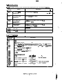
5.3 SX-IO1 card
._
m-.--w
em____
_
...
.
,
-
-_- -.
VRll
VRl3
VRlI
G2
d VRlS
;a-
.
_.-. _-
---
___ -..
._
A
1
.-__- --._
r&L10
’
0
-24
15
vlwc7
CON 12
o-25
a.
O&I26
_
.-.
D
c
-
,
n
*
..=
.*
--
_
-
___._ - _
-=
List oi LEDs
ckscription
LED No. j Symbol j
1
LED12 I
AL8
LED13
AL4
LED14
LED75
1
AK
1
’ i Alarm dispiay (For details, refer to “List of alarm signals”.)
I
AL1
1
Speed command display
LED1 01
Xl
\
xi
x4
..
..
i
X2048
LED112
t
12bits
4
List of setting pins
Pin No.
PIN1
.
Description
Symbol
* A-TOP Ht~ll) speed
Seeed
setting
6000 rpm (Base speed 1600 rpm)
4600rpmh9peeUl60rpm~
B - TOP (full) qwed
4600 rpm (Base. speed 1500 rpm)
3460 fpm (Base sved 1150 rpm)
.
.
.
.
i’
:!
I.
I
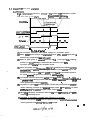
List of alarm signals
_. -
- - -
_ ._ --..- -.~ Output = H level (Transistor turned off) __
Output - L level (Transistor turned on)
0: LED does not lighf
1: LED lightr
Output
j
1
0
0
0
0
3/O/
0)
4
I.0
0
so
.
MOTOR
OVERHEAT
1
20
t
0. B R E A K E R
TRIP
10
7
0
1
0
1
81
0
910
*I
10
PHASE I:0 SS
1
Any phase is dismnnectcd
EMERGENCY Emergency stop
pu&button on an
STOP
external operation
panel is depressed
to “ON”.
1
1
OVERSPEED ‘Motor speed
exweds 115%of.
0
0
C O N V E R T E R & c u r r e n t flows
:r~W. OVERCURRENT
0
1
Stop the motor,
eliminate the cause
and depress
ALARM RESET or
RESET button.
Unusually high
toum current flows
causing tripping of
breaker.
.o
1
I
0
Temperature in tie I After cooling the
motor goes up over motor, operate
the limit (15otBC1 ALARM RESET or
RESET button.
1
!
1
I
l.Forprovision
!
6
i Resetting method
Motor spe~~I largely
EXCESS
differs from comSPEED CONTROL ERROR mandedspeed.
Detection speed
emx 9 (3000 rpm)
0
1
Cause
Alarm
IO. 1 AL8 1
AL4
AL2 AL1
(LED (LED (LED. ( L E D
T5)
141
13)
12)
._ __ ____._._
I
1
I
_ _ _._ _
I
0
Operate tie emergency stop pwhbutton to set it
“OFF”.
(!z!z!q
U n i t : 6025’C ’
i-lest&k: lOCrS$
. ..
CONTROLLER Tempaature of
heaaink is too high
OVERHEAT
SOURCE VOL. The input source .
voltage is below
TAGE DROP
l7OV for 15msor
longer.
. i
.
._-
!
I
Output
I
/
I
1
4
Alarm
IvcJ. : AL8 j ALQ j AL2 j AL1 /
! (LED: (LED 1 (LED ; (LED j
j 12) :
131
I
14) 1 15) j
11;
I
!
0
/
1
13 /
1
14’
9
1
j
1
I
t
i
i OVER/ VOLTAGE
1
I
I
I
I
i Resening method
Cause
I
i DC voltage in the j
i convener is too
I
i high.
_.-
Traubie ocxurs with I
microproce!ssor.
I
0
I
CPU
TROUBLE 1
1
1
0
CPU
i Trouble occurs with
TROUBLE 2 1 microprocessor.
1
CPU
TROUBLE 3
Currently not used
15/T
.
.
1
1
.
.
.
.
P i n
N o .
Description
For source input
__-----_-
C. D short-&&ted
PI N3 opened
A, 6 short-circuited
For sync input
PIN3
.
.
Name
DIGITAL SPEED
COMMAND INPUT
MODE SELECTION
PIN2
.
.
.
.
.
Trouble occurs with
microprocessor.
I -..- .-.-
.
.
BCW2r735-S5’
N/43
‘.
.
List
of check
terminals
.----
Description
OV
Tarminal No.
PSA
+5v
OGA
OV (Digital ground)
CH3
AGA
.
Analog speed command input TOP (full) speed c lbv
CH4
Ovemumnt setting level (Operat level + 1 OV)
CH5
Ovefummt setting level (Opemt level + 1
CH6
Convenaf voltage, feedback
5v . . . WC = 2oov
CH7
“U” phase . . . lmmrter cunm detection
CH8
‘W”phase... lnverter current detection
CH9
Sou,TV current detection
. ..tAC-(RatadcurrentIxJZ- x4
Cl-l10
-. -- -. ._.
_.
ow
“3
Invemr “u” phase and ‘W’ phase current rectified
CHll
. . . IWM - mated amed xa
.
CHTZ
Reference voltage +l OV
CH13
Refwence
Cl-i1
Override command
+tov., . 120%
CH14
AG8
~0ltaga
“w” phase
-i ov
reference
Adjtible by VR39
sine wave
n
CHl5
AGE
“v” phase reference sine wave
C1-116
AG0
‘V’ phase reference sine wave
u
1
6.5v - TOP (full SPoedl
WV -TOP tfd srmd)
_ -
Gil7
I
CH18
.
CH19
CH20
AGB
“U” phase voltage integrator output
CH21
AG0
“V” phase voltage integraxor output
CH22
AGB
‘W” phase voltage integrator output
CH23
B--PI 7 355s 5 N/J4
.. I .
..
I
Description
XIV
‘ermlnal NO . i
NlAl N Cl RCUIT / Convener voltage on main circuit side.
I
SIDE
,
(324
_,
’ /’ nverter
current “U” phase on main circuit side
I
CH26
CH27
j k&p ClRCUl
MAIN
1 SIDE
CIRCUI T
.
It nvemr transistor base drive signal
,“U” phase
1 3V main circuir nansistor “ON”
Cl428
/ bl”o:” CIRCUI
lnvernr ttansistot base drive signal “V” phase
OV main CirCU‘IL tiSi.StoP “ O N *
CH29
W&l ClRCUl
lnverter tmnsinor base drive signal ‘W” phasa
OV main CirCui t trcUISiSt0~ ” ON ”
c1-130
MAIN CIRCUI,T
i SIDE
I nverter nansistor bass drive signal “U” phase
0 V m a i n cirCU;L bW’tSiSt3P ” ON ”
w3t
1 MAIN CIRCUIIT
1 SIDE
lnverrer Fansistor bass drive signal “V” phase
QV main circuit tmnsistw” 0N *
lnvemr tansistor base drive signal ‘7N” phase
Q V mdn circuit tmnsistdr ” 0~ *
CH32
k.
T/ I:nvette: cunenf ?I” phase on main circuit side
CH33
AGB
lmwmr
CH34
AGB
Inserter *Y** phase voltage feedback
CH35
AGB
lmnmer W’* phase voltage feadback
CH38
DO8A
lnverter “LT’ phase base ampiifief output
Cl439
DOSE
lnverter 7” phase base amplifier arq3ut
Cl440
DO8C
Invetnw W” phase base amplifier ou&
CH36
CH4t _
CH42
CH43
“U” phase voltage feedback
! +5.N
1
%+,N
VDC.-14OV
_.
_ __
I
D08D .__ _._
--.- ! DO8D
~DO80
lnvwcer UP. .phase
base
amplifier output
a.. .-__. .._
:
__
lnwrter + phase & xfmplikr gutput’
lnvmer T phasa base amplifier output
_ __
_
---..__
_
_-_-‘C
-
.- - ,.
. i
.
! BCN--2L7~5$5
___a.
B/45
n .,
I_&
_-.-
_ ----
.-
of variabie resisTon
.__--Sin- all variable resiston except for VRl and VR2 have been set by us, do not change ?he
serrings.
.
L
INO.
Description
VRl
i
I
t Speed meter caiibration
VR2
Load meter calibration
VR11
Reference sine wave “U” phase D/A converter gain adjustment
VRl2
Reference sine wave “U” phase zero adjustment
VR13
Referenca sine we “V” phase D/A converter gain adjustment
VR14
Referenda sine wave “U” phase gain adjustment
VRl5
Reference sine wave “V” phase zero adjustment
VRf6
Reference sine wve ‘W” phase gain adjustment
VRl7
Reference sine WaVe “V” phase gain adjustment
VA18
“U” phase current balance adjwtrnent
VR19
“UI’ phase current balance adjustment after gain selection (low speed)
V RZO
‘V” phaaa currant balance adjustment
V R21
‘If’* phase awmnt balance adjustment after gain salaction (low speed)
VR22
“VV” phase currutt baiande adjustment
VR23
‘W” ph;aa current balance adjustment after gain selection (low speed)
VR24
Reference sine wwe “W” phase Ieve! adjustment at gain selection
VR25
Referenca sine wave ‘Y’* phase lava1 adjukrnent at gain selection
VR26
Reference tine wave ‘II” ph&e level adjustment at gain sealaction
VRZ?
I nvemx “u” phase voltage feedback adjustment
CH23
vR28
lnverter
l *V’* phase voltage feedback adjustment
CH34
VR29
inverttar ‘W” phase voltage feedback adjustment
CH35
VR31
A/D converter zero adjustment
VR32
CH6
VR33
Converter voltage feedbeck gain adjustment
i
Current limit level setting
VR34
Ovenzwnant level setting
CM
VR35
“U” phase awremt feedback zero adjustment
CH 7
VR36
“U” phase cumnt feedback gain adjustment
CH?
VR37
‘W’ phase current feedback zero adjustment
CH8
VR38
TV” phase current feedbck gain adjustment
ma
VR39
2 7 OV Reference ~unza voltage
CH72$H73
VR4C
Overswed level adjustment at “L” speed setting
PlNl-8
VR41
Ovemxed level adjustment at “H” speed setting
PINl-A
To
1
beaset by user
__
-
---
-
-__ --. -
CH16
.“3
Cl-l15
_- -
’
.
CH4
-c-.
?
,’
N
.* . -
. :
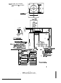
This card is ;he power supply unif -ha: provide P”R-SX wifh all necessary DC sources.
Mote: Although tiere are two Woes of SX-PW card, which differ from each omer in pan
ioading oxfern, rhey are completely comoarible.
! _ BlookC
_. .
,
I
!B&ck 0
e
DO8D
1
\
,
7
I_-e_E
I-_ .-_ _
!_Bbe+*
__
_.--.
_
r
-
.
_
-
_--
.
-
_ Now 1. Tha card is divided into 7 blocks ranging from block “A” black to block “F” and
“0” lint of each block isseparated and insulated (‘O”Iinf?s in block an connected).
2. Blocks ‘3” - “f” are not insulated from the main circuit
.
.
B=ZL735..S5
_
.
N/47
. ___-._
Dl-
Block “A”
OGA (OV) i +5v 2 3%
15a
/ AC DOWN
i
j
AGA (OV)
j c15v 5 1 . 5 %
I
j
ov
NlSA
1 -1sv f 1.5%
P15A
P24
.
P58
mick “8”
P15B
0024(OV)
IX8 (0’4
/
Comrol source voltage drop detection signal
Cmmi power source
*
+24v
*vr3%
ClsV 2 I.%
,
conuol power soums
AG8 (OV)
NlSB
Uninsulated part
-1sV f 1.5%
‘“3
I
PSA
Black “C
‘W” phase base pow& soum
DO8A NSA
Block
9”
.
P88
DO80
N8B
Block “E”
+BV
+15%
- 5%
I
?I” phase base power sourcn
ov’
-8V
+15%
- 5% t
“3
P8C
008C
‘W’ phase base power source
NSC
Block “F”
P8D
l
0080
“U”,
N8D
foUrch
v**, ‘7N” base power
. .-
__
. __. __ . .
.-a.: .i .+..L.
L
-&
,,.a;B.;._
_
--
.-_a
.-_.
Lk of LEDs used in SX-PW
._
*
‘
I
LED No.
LED1
LED2
I
Descriprion
!
I
1 +5v. (P5Al
I
I
+15V (PI 5A)
Lights when voltage is a7 normal levei.
Lights when vottage is at normal level.
:;
’
.
-15V (N 7 SA) tights when voltage is at normal level.
ED3
1
LED4
+24V P24A)
Lights when voltage is at normal level.
.
Nom The power sauce is unusual if the output vol~ge is not within the range listed in the
previous pages even when the LEDs light oh
The inout power source to this card is specified to AC127 - ACSV, 50/50Ht
4
...
. :
.
.
__
5.3
SX-AJlcard
This card is used for auxiliary level settings necessary to adjust the input power source,
pmteczion (afervj circuit, current, voltage and feedback
SX-IO1 becomes repiaceable by adjusting this card.
30 Control cifwis
inout Oorrm sour0
canumrwmage
Jhnur sloe1
c
--
s-e-
..__-
_.___.--.
.-
-
-
Connrt8r inout AC murc~
CT OUUuI
=wmnt
-_
__ aececcIon
/
t) w -
--
-
_
_,_-
_
.e..-.
Description
Variable resistor No.
VRIOI
I nvmsr “U” phase current detm level adjustment
VRlOZ
Invemr ‘W” ohase current detect levei adjustment
+mlo3
lnvemer voltage feedback + voltage b&an=_ adjuslment
VR104
INRW -N” o-
_~-_OO~lM
1
Input current feedback level adjustment
.’ _
I
.
2
CHAmER 6 SPINDLE ORIENT POSlTlON DETECTOR INSTALLATION PROCEDURE
_
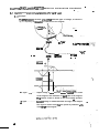
6.1 Magnetic sensor singie-point oriemsrjon (SX-CPU 1 card is used)
’
..
_.
6.1.1 Principle
me sensor (d-or element) produc?s twa different types of voltage, as shown in
Fig. 6.1, depending
on irr lockon in reference to the magnet.
-
-- . .
_._ _
- ---___
__.- _- _ __ __ _
-. -.
__I,.
- ._
-__.._
---_
e-w_ _
-
___ _
_.
__
t
MS signal . .._ . . . . . Output voltage is z&o when the sensor is locared at the center
of the magnet, and maximum at bati ends of the magnet.
The position control is based on the zero voltage position.
...
LS signal . . . . . . . . . . Constant voltage is maintained within the tangs of the magnet,
This signal is used to verify aat the spindle is positioned witfiin the range of the magnet
.
6.1.2 Time chart
Fig. 6.2 shows the time chart of each signal.
Usual operation soeed
Smfo nnnol soeed
-_
.Oricntatign sp_@_
.
\
I
OllCl
(Ori_@rmb,a~_~_=_~g~
I
I
UPTS
!?h~??o~d_s~~
SI..
(SLOW
TIMER) (Saitwad
_.--- DOWN
_ _ -_-- e-
salvo
Ir4_
_ _ cDntrol.
_ _
?OOm
?-i_
ORAl-ORA2)
,QlklTatiorr cwndafg)
LODS
r
I(INP’XL F!NE)
(1) When
ORCI (orientation command) turns on, the motor speed changes from
usual operation speed
to the
orientation speed.
(2) When the motor speed reacha the otientation spe$, tie threshold spec!d signal
(LEb7) rises.
(31 AFcer the occun-enca
of threshold sp& signal and when-the sensw Ls signai
turns to “L” level (when the magnet just passes over the sensor!, the “dow down
timer” (software) ~arec counting.
(4) The timer is set ats~2-5,~,7 When the timer counts up, orient speed commf mode
charqes from the speed conuul loop to the position aytrol loop (servo, IN).
(5) Under the position loop control, the spindle stops when the sensor MS signal
reaches zero volt.
. i
(6) When the spindle stops at the predetermined position, the orient cxmplerion
signal risas and ORAl-ORA2 (oriem ampietion axxact signal output) c!oses in
3X ms aftar the stopping.
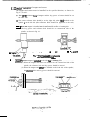
6.1.3 Dire&on of insdiatiofl of magnet and sensor
The magnet and sensor must be installed in the specified direction, as shown in
Fig. 6.3, 4 and 5.
(1) The cmter reference hole of magnet and the key groove of sensor should be on
the same side.
(2) The center reference hole should be on the right side when tool attached to the
spindle
is
on the left side (the reference hole should be opposite to the tool).
Case 1 When the magnet is installed on circumferential surface of rotating disc . . . . .
The key groove and reference hole should be on counter-load side of the
spindle, as shown in Fig. 6.3.
Iv_iew Bom”A’f,
___
.
..*
.._
_a.
_
- _s.--.-
Raiarena
- ._ _._ hole
I
fig. 63 Magnat i&Id on ciraamfdal
awfaca of rotating dkc
-
-
L
Casa 2 When the magnet is imtalled on the side faoe of rotating disc . . . . . . . . . . . . .
/I
(1) When the magnet and sensor are installed on. the counter-load side of the
spindle, the reference hole and key groove should be inward.
(2) When the magnet and sensar are installed on the load side of the spindle,’
the reference hole and key groove should be outward.
/ \
Kay woove
F(efcrence hole _
Refenna hole
View fmm ‘C”
Kw omove
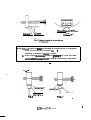
Notes: I. Wbti magnet and sensw am installed in wrong direction, as exemplified
in Fig. 6.6, the spindle is indexed no-L
.
depending on direction of rotartion of spindle.
2
If the magnet refemnca hole and the key groove are not on the same side,
osciikion occurs behwean bo& dges of magnet and indexing is impossible.
. .
.
.
-
FG 6.6
e-m...
__. .__
_ _. _.
Fig. 63 .
.
B-2 17j335 N / 5 5
.
6.1.4 Cautions on imcailtion of magnet
The magnet should be installed with the following cautions:
(I) Do not allow access of any other powerful magnetic object to the magnet.
(2) Do not give physical shock to the magnet.
(3) Secure the magnet to the spindle using M4 screws.
(4) After the ‘magnet has bee!n imtalled, check and adjust the balance of the spindle.
(5) Adjust the mavet so that the center reference hole of magnet is aiigned with the
center of rotating disc (itr direction should be as iilusted in Rg. 6.3,4 and 5).
_ ______ -- --
(6) Clean the vicinity so that malfuncrion due to adhesion of imn pwtides to the
magnet doa not occur.
_ -___. - - -
(71 Apply “lock paim” to the damping screws to prevent the m from becoming
loose.
’
(8) Since a ground rotating disc may heve been magnetized, demagnetize the disc
3
when the magnet is installed on a ground rotating disc.
(9) The diameter of mtating disc on which tie magnet is installed should be within a
range fmm 60 mm to 120 mm. Howavtr, disc of large; diameter may be used
-,
_-_
when the spindle mtata a low speed.
6. r .5 Cautions on installation uf sensor
-
-
- __
The sensor should be instailed with the following cautions:
(1) Install tie sensor so that the key groove of sensor and the magnet reface hole
amonthesameside.
12)
Align the cmter of sensor with the center of magna (see Fig. 6.3,4 and 5).
(3) Adjust the gap.between be magnet and the sensar to 1.5 mm f 0.5 n?rn for
insrallation shown in Fig. 6.3, and to 4.5 mm f 0.5 mm for inrtallation shown in
‘It is recommended for mass production to pmpam a gauge for this adjustment.
(41 Although the con-r of the amplifier & of oilproof, it should be loc?tW away
from oil.
-
(5) Segraga* the cable beWeen the amplifier and the controller unit from the power
-.
CiluJit cablet
(61 check the connecxar wiring, secumiy sert the plugs and tim lcxk szrews of ea&
connector.
.
‘BCX-217jS-S5
_ _
N/56
:’
-.-
I
I
i
1
k!!z
.-we
-.
--__
P
I-L
iTalcrana to mounting
idimension:
- 22 mm
6.1 .S Overail view of magnetic sensor
( 1) Magnetic sensor
1
P
.----..-
--
__
_
Magnet
Pun&d “nar hom
47.5%?
-- g _
_
-.
3 Ampfiiiw
5.2
Enwder vpe multi-point oriemation
6.2. ‘I Pnnciple.
Pig 6.10 ~hematicaliy snows the principie of the encoder type multi-point orienta1 SOed SOWWd L?Y PoSrtloning
tion in the form of time &art
i conuol ampiifiar gain
3
c:
Mozor weed
I
Orientation comrrund
(ORCI-COM)
Markpulse
_-_
I
I
-.
n
i
n
II
n
I
In-position signal output
_I I
’
.
1 Fig.ao mmachmt .
.
._.
.,
-_. _._ __ _. __
(1) Wii orientation command, motor speed changes to “orientation speed”.
12) When motur speed reaches the oriemmion speed, ur to
speed signal (that .it
detected by comparator) rises. (S&WU,FZ)
(31 When a mark pulse is acbpted after the UP to
speed
signal rim, indexing
position data (12-hit binary) is read and at the same time count starp.
The motor speed remains at the orientation speed.
fore the predetermined indexing (orienta(4) When the spindle reaches
scat;* value @Peswz-5n6.7
tion) pbtion, the Eontml mode changes from the speed wntrol loop to the
position control loop and tie motor spead changes from the orientation speed to
the speed gbemed by gain of the positioning mntml ampiifier.
before
*
(5) The spindle enters the positioning con001 loop linear zone at
sttinj valve 04 sw 2-2s
the pmdetermined indexing position and the matw is dacelemted and then rmps
.
at the predetermined indexing position.
-.
(6) “In-position” signal risq when the spindle reaches the point before the predmrminad indexing position by a direancc (angle) equal to SW7 ting. In about
200 ms after that, “In-ppsition” signal output contact closk
(71 When the orientation command is removed, ttre motor stares rotatingat the cornmanded (S command) speed.
(81 Repeating of orientation is possible after one turn of the spindle.
However, the spindle rotates over one turn depending on extemally &nmanded
indexing position and stings of !W1O;SW9 and SW.
.
..
.
6.22 Encoder type muiti-point orientation system comoosition
’ G3nttollcr unit
1
r
r---T
!
N/C
‘LA
I
i’ SX-CPUZ
‘Ckhfmtion mnmmnd
cDp( c l_(lZ-bit
binuy)
-.__
-
i__J
1
*
1
L
_
._
-.
Nova:
.
If dimeion of rotation differs between the motor and enaxkr, due to-mduction gear meshing, adjust it by opeting DIP switches SW2 - 8 of SX-GWZ
. :
62.3 Overall view of encoder
(1) Dimensions; of encoder
.I Detail of kw slot
:
8
m
N&:-~Ma& p&d Lid-ri~GS) should be rqual to widxh
of 5 pulses (lohA and 1dW.
If mark pulse width differs,
ROM in the contmiiar should
be replaced.
_
_
--_
_.
_.
asa
._
CAMKW
_-
hls31a2A2D-29P
Output renninal anangement
Al
l&A
B 1
2&A -IL
C(
l&B
bl
E
, J I
0~
CasmGNO’
P
I
L
M
PI
F
d
H
hd
YChA
1
‘2&A
R I
‘“ld18
1
-.
I
MSSO57-124
-_
(Cable conneeoris not
-.. furnished)
= I
+5V
Tl
culnexQr
%vefsing signaL .
I/l
.
_
CHAPTER 7 TROUBLESHOOTlNG
-_-
7.1 Preliminary checking
___.-_ _-. _.-If any troubie occurs with the controller unit, it is recommended-tdp~llowlng
simple checking before starting the troubleshooting.
The preliminary checking is very helpful when you consult with our service agency.
Preliminary checking in case of controller trouble
1. Does any alarm lamp on the controller front panel light? If yes, identiiy the lamp.
2 Is any fuse blown out?
If yes, identify the phase, fuse of which was blown out (R, S and T phases).
_
3. Is the same failure or trouble reproducible?
_
_-_
4. Are the ambient temperature and panel inside temperature within the specified range?
5. Did the trouble occur during acceleration, or deceleration or steady-speed operation7
_
6. Is direction of rotation proper?
7. Did momentary power failure not occur?
8. Does the same failure or trouble occur with specific operaion or command?
_._,-_
9. Does the same failure or trouble occur frequentiy?
10. Did the trouble occur when load is exened, or when load is removed?
1 I. Was any part replaced, or any remedy is done by yourself?
12. How many year has been operated the controller?
13.
Is the source
(line) vokage proper and sabie?‘Does it change depending on time?
7.2 In step troubieshoating
Perform the following checking & the 1; step of troubleshooting.
(11 .Sourct voltage . . . . . . . 2OOV f 10% 50/60kt, 21ov.22ov23ov 2 lo?& 60Hr
In any case, the source v&age should not be below -10% of 2OOV.
Examples of soum voltage drop:
l
Volage drops at a certain time every day.
l
Voltage drops at start of a specific machine.
(2) Are peripheral wntrol functions pmper?
Examplee of checking:
l
Are NC and sequential contmi circuit in good condition?
m Is any failure or defect found in partz or wiring when checked &ually?
131 Is the temperature amund the controller unit (and in the unit) wihin 50’Cf
(4) Does the cmtroller unit present good appearance?
Examples of checking:
:. .
* Are card componerrts, cinzrit patterns, erz. in good condition?
0 Are all wires securely connect&?
Is any part not damaged?
It: there any foreign matter?
.
(5) Is the DC source output SW-PW at the soeciiied level?
The cause of the trouble may be roughly identified airtr the above checking.
The most likely troubles with FR-SX can be categorized as follows:
The controller mmed on for me fim rime does not work
/- sarisfacxorily . . . . . (1)
I
i
T r o u b i e ‘“R” I
The controller that had been working in good condition came
into scar&till . . *. . (II)
The controller comes into srandstiil from time to time and stop
,
pctsitionisnotaiwaysaxact.....(III)
r
Trouble “8”
Defactivc.semicondoctor element in main circuit
Controller tmubie
Control circuit trouble
Speed dete&on encoder uouble
Detector trouble
l-
Multi-poim orientation encoder trouble
t
L Singbpoim orientation encoder trouble
.
i
Power soufca u&la
\
Motor trouble
L- Other tmubles (incomplete input signal conditions, open circuit due to dib
connected wire or cable, eoc) .
.
'BCWZIi33~,SS N/63
*
.-
7.3 2nd step troubleshooting
Trouble
I
(I) j
~ntroller turned on
:or tie first time
ioes not work
atisfactorily . . .
Check-up
Since all units strictly and repeatedly diecked before shipping, the most likely cause of
the trouble is,
(1) The controller was damaged
. due to large shock or intense
strike during transport or
installation.
-mey
--
(1) Visually check the appearanca
of the controller for damage.
(2) Wrong external wiring,
sequential control error,
wire/cable diwnnection
Is grounding wire connected?
Note: Difference in phase
sequence does not cause
any trouble.
(2) Make sure LED1 - LED4
(power indication) of SX-?W
light
Check-the+xtemal-wiring and -. ----: ____.._
sequential control.
(31 Check ROM No. and DIP
switdl seccings against the
the order shnt
,
(3) Repiacs ROM or change DIP
switzh strings if necessary.
‘(4) The motor doea not &I at
the specified spe&
(4) Interchange motor armature
connection betwetn any two
of threa wires (U, V, WI.
(5) The motor can an s&facmrily only when load is not
ex+rted.
(5) Check that the load meets the
design vaiua.
(6) Exact indexing is impossibie
(stop position is not exact).
(6) Adjust
(7) Controller alarm LED AL8,
AL4, AL2 or All (LED12,
LEDt3, LED14 or LED151
iightr
(7) Refer to para 7.4.
x
*
1
Trouble (I I)
Controiler that had
been woring in good
condition came into
standstill . . .
Check-up
(1) Check if fuse is blown out,
or main circuit no-fuse
breaker is tripped.
Remedy
(1) Replace blown out fuse.
If the new fuse is blown out
again, periorm the 3rd stop
apubleshooting.
Check-up
Trouble ( I I)
(2)
Remedy
Check the ingut power source.
ACZOOV f 10% 3OHr
AC200 - 23OV z 10% SOHr
(2) Restore the power source if
necSsary.
The power source, should be
that the power requirement
*own to the left can be
satisfied at all times.
P
(3) Controller alarm LED AL8,
AL4, AK or AL1 (LEDIZ,
LED13, LED14 or LEDIS)
lightr
Refer to pas 7.4.
(4) Check the input signals from
NC or sequenGe control.
LED? (READY) should light
when the system is ready for
operation.
LED3 (CM!) should light for
CW rotation start.
LED4 (CCW) should light
for CXW rotation stab
14) Enter the correct external
signals
*
S) SWl-2 ‘TIFF” open
SW3-3,4,5 “OFF” cushion
Check if “open” operation is
possible by operating RESET
’
b u t t o n (103).
5) Speed feedback encoder is
defective if operation is
possible (replace the encoder).
If operation is impooible, the
trouble will be attributable to
the main cirouit (aiann LED
will light).
Trouble (111)
Check-up
Controller comes into
It is ve-portant to be exacrly
aware of the conditions under
u&id? the trouble oa~rs (load
condition, operation mode).
The cause (3) is potisible.
standstill from time to
time e . .
Stop PO&ion is not
exact at all timer
,
Alarm LED lights.
Condition is restored by ( 1) instantaneous power failure
turning on and off the
or source voltage drop or
power, or by reserting.
“NF TRIP” (when instantaneous power failure
occurs during generative
braking)
“CONVESTER IOC” alams
ED may ligtn
(1) Check the power source for
source voltage regulation.
. . .
r
I
Check-up
Trouble (1111
(2) IMalfunction due to extremely
large noise
The controiler itself can wirhstand the line power noise up
to 1600V/ins (max. 2OOOVl
lus) in both common mode
and normal mode.
(3) Check if load increases
momentarily due to vibration,
or the like. Check with a
particular care if indexing
error occurs
- - .--- Identify
&se
source and
(21
install noise suppressor to the
noise source. Check grounding (parciculariy
grounding of detector).
Check case grounding.
i
(3) Carefully iheck the I&chanism.
. _ __-_,.
-d
7.4 Detaiied checking for each trouble
_
_.
-
-._.
.-_.
1. If alann LED lights. . .
-’
--
Current does not fiow into OHS1 and OHS2
Check-up
Over-load
1. Check the motor loading
condition.
2 Check m&top frequency.
Fan trouble
Check the fan motor for
condition.
Motor air
Check ventilation (air feed rate).
intake dogged
Thermal
protector
aoubie
Check if resetting is possible after
rotating the motor fan for several
minutes witi the motor stopped
:Ecwz 173Tk5 N/66
.
_-
-.--
.__._ _. __.._ - --.
-
(11 MOTOR OVER HEAT
I
_
_ _ ,_ _ _ _. ._ _- --.._---
The alam LED of the protection that first gets into function lights.
CdUS0
---
1. tighten the load.
Remedy or ~place the fan/fan
motor.
Clean.
:. .
1. Shoticirarit between OHS1
and OHS2 and continue the
operan’on.
2 Replact the motor. -
‘--
. .._---
When speed control error (difierencc between commanded speed and actual speed) is
larger than specified level (500 rpm) . . .
_
_
__- ._
Cause
Over load
_ _..
. _. _._
Check-up
1. Check the motor loading
condition.
Speed detection 1. “Open” operation is possible.
encoder trouble
Card trouble
1. SX-cPUl or 2 card,
Remedy
I. tighten the load.
1. R epiace the encoder.
1. Replace the card CPU 1 or
SX-IO1 card Double
CPU2 first and then 101.
(3) BREAKER TRIP
LED lights when the main no-fuse breaker trips.
It is possible that IOC (converter, inverter) lights fir%
Power fource
vottage drops
beiow’l80V.
Check if source volege goes down Since tmnsiem voltage is likely
the specified level during de&era- to drop below 18OV if source
voltage is near f8OV during usual
tion (regenemive braking).
operarion, boost the sww
VQltssc
1~tL&L+tiry
~~~thedescyiption
aboA
a
trip
(Refertothe
description
about IOC trip)
_ _. _._ . .__- -__ .a.--_. _-.-pm-_. _. ._ _
IOC
b
. . .
o
u
t
;. .
. :
.
__ _ __._ --- --
1
cause
Remedv
__._
CSeck-up
Converrer volt- Chck tie maximum speed start/
stop waveform when tie conage asciilates
during de&em- ) vetoer is under full-voltage load
i condition.
tion
_I_
‘.
I
.---
3 Change accelerarion/dacslea
tion c0nscm.
______.__._.._
._
3 Change load GD’,_
o aepiacecard SX-I01 if necessary.
_’
--___
---_
___
Open and close the no-he breaker
(power) to check the power.
_ __ --- ..-.
-
(4) PHASE LOSS (PtiASE DISCONNECTION)
AL4
(LED131
I
0
I
I
1
AL1
(LED151
1 L%4,
I
0
.
I
1
.---.
Check to see if the axrresponding alarm LEDs light when the power is turned
I
CaUW
OR.
Ramady
M-UP
Three phazes should be connbcred
Any phase is
disconnecred
CSeck voltage at aa& phase.
Fuse Ft ,2 or
3 is blow out
Chack dre cause oi blowing out of Raplaca the blown out fuse.
fuse (shortcircuiting, for
exampleL
(5) EXTERNAL EMERGENCY
1
0
I
1
I
t
I
0
I
The Trrctsponding LEDr light when external emergency stop sign4 is given.
A chedc the QUS~ 0f emergency stop ad thm rcscf
,
‘.
(6) OVER SPEED
.
’
--
-.
.-
The LEDs lighu as shown above when the motor speed exceeds 115% of the maximum
.
speed and tile over speed de-or trips.
Cause
.
Check-up
/
Remedy
Improper max. ) Check the settings of SX-IO1
speed setting f PIN1 and SX-CPU SWI-7.
Correctly set if necessary.
Speed detector Check the encoder output
CPUkard Cl459 - CH67
trouble
hi60 - CH571
Crul c+pCH96 cc CH 54
2
5-t i-j 9J
Replace the detector.
512 x 1500 _ ,2.3KHt
.
60
at 1600 rpm
Replace the card SX-CPU first and
*en
SX-101.
Speed amuol
Defective cards
detecting cinrrit
trouble
.
(7) IOC TRIP (INVERTER, CONVERTER)
Converter IOC
AL4
(LED131
1
lnvener
0
AL1
(LED151
0
I
I
0
IOC
IOC trip occurs on the inve?er side as well as the converter side, due to overcurrent
Check the cause ofpveppnt
It is likely that a$%r%%uctor elemem is damaged if IOC &p occurs again when the
ipE5r7 bunon is depressed..
CaUSe
Paver
transistor is
damaged.
-
checkup
;
Remove the conneczion between
the controller and the motor and
opeme only the conwller to see
if the alarm LEDs (IOC TRIP)
light or hot
l If LEDs light the power transsisror is defective.
l If LEDs does not light, proceed with the next step.
I
T
Remedy
-.
...
Replack the power transistor.
.
I
Check-up
Cause
Remedy ___ .__
7
To large motor
load
Check -he load fo the motor.
tighten the load.
Wrong motor
wiring
Check ttre motor wiring.
Check terminal screws for
looseness.
Correct motor wiring if necessary
Tighten loose screw.
Motor winding Measure the insulation resistance.
If insulation resistance is smaller
layer shortthan 1 IMegohms, the motor is
circuiting or
defective.
grounding
Commutation
fails at regenerative
braking, due
to low source
voltage.
The source voltage should be
Too small
power source
CaPaChY
Source voltage should be at I1SOV at acceleratie&Lcelemtiatior
as well -as under loaded condition
sower source
joltage waveion-n trouble
3bserve the source voltage waveForm during acceieraxion and
hceleration using a sync!!roscope.
1. If voltage discontinues
panialiy . . .
larther than 18OV at R, S and
T phas
.o-
Increase power source capacity.
Improve waveform.
1. increase the power source
capacity or us8 a cable of
larg8f size.
2 Remedy semiconductor unit
that causes deformed wave.
fom
JF-f-SMW
- twru
2 If voltage is chopped . .~.
.
Replace defective motor.
Boost the power voltage.
..
-.
--
*
! source frequency should not
Sourc8 frequency trouble! Ihang8 over 23%
Improve tie power sourfx
Current detector circuit
trouble
Replace card SX-101.
Ilnvertw CHft - AGA:
IOV peak
tConwz~r CH9 - AGA:
1
rOVpeak’.
_-
.-_
P
_
.
(8) CONTROLLER OVER H E A T
/
0
(L&
1
I
/
&43)
0
I
i
1 (LrDl
tL1-3)
(L$4)
0
I
i
Tine alarm LfDs light as shown above when the controller thermal protection works
(cooiing fan installed).
Check-up
Cause
Remedy
1. Lighten the load.
O v e r l o a d 1. Check motor ioading WI)dition.
2 Check start/stop frequency.
Ambient ternperature is too
high.
2. Decmasestart/stop
fnquency.
Measure the ambient temperature
around the controller.
I
Thyristor cool- Check the cooling fan operation.
ing fan trouble
If the temperature exceeds SO’C,
cooling method shouid be imPm.
Replace the cooling fan.
‘
(9) UNDER VOLTAGE (VOLTAGE DROP)
I
1
I
a
I
I
I
0
I
The LEDs iight as shown above, when the input source volw goes down beiow 170V 164V for 15 ms or longer.
+
.
cause
When usual
operation can
resumed afrer
nisenring.
The LEDs light when speed is
ctranged or too large bad is
e x e r t e d .
,
When the
LEDs light
When the input power source is
normal, the most likely cause is
SX-PW card trouble.
Signal level across SX-PW terminals ACDOWN and DCSA is to
be “H” level when the control
ciradit is normal (+SV).
COfltiftUOUd~.
l
C h e c k - u p
I- the powersourrr
capacity.
-.
Replace SX-?W card.
..-
*.
_
.
(10) OVER VOLTAGE (CCNVERTER)
The LEDs light when the v&age in the incorporated smoothing ca~a&o+.azce& cbe---
__
permitioie level.
cause
Check-up
OVWbd
tf the LEDs Ii& during deceleration of motor, check the load.
GD’,
If the LEDs light during deceieration of motor, check the load.
is too
large
ConveKer
,
voltage conu-01 is not in
good condition.
Daecmr circuit trouble
_I..___ - - _ tighten the load.
CheckthatwltaqacrossPandN
terminals of main circuit capacitor
is below DC25OV under usual
operating condition, and if ‘rt
changes depending on the
If the voltage exceeds 25OV, or
does not &ange d_ep_ecdiqp_on _ __
the speed, the cause of the aoubic
is defective convereer,_ __.__._ _ ___ .___.
Repiace SxlOl card
L
.__ ._ . Replaca SX-CPU card
Ifthecweoftroubleisodwr
than described above, trouble
with the detector circuit is’
pokkk
Replace sx-IO1 card
(111 CPU trouble
I
1
1
1
I
0
I
1
I
CPU troubler in&de arithmetic operation war or logic wmr.
Reset and try oparaian again to see the condition. Card or CPU chip must be replaced
. ..,.
depending on the truuble.
.__
.-
2. Troubles that do not cause lighting of alam LED
(1) The motor does not run at all though no aiatm LED lights.
I
&US2
j
I
..
Remedy
Check-up
Wrong wiring \ Check the wiring.
or wire disj
connacted.
I
Properiy connec: wirer
Unusual power Check that the source voltage is
source Voltage at zaav 5awzaa - 23av 6aH2
Restore the power source.
change
.DC sowoe
Check all output voltages of
SX-PW card using a multi-metrr.
Replace the card if necassary.
Card trouble
Opera= SWl-SW2 to “OFF”
(usually “ON”) for “open” mode
and check that the ~ferance sine
wve occurs when commanded
speed is incmd
When the card is in good condii
tion.
Replace casd SX-101 fim and
then SX-CPU.
trouble
sx4ai hard
CH16-AGB
CH15AGB
CH94-AGB
terminals P and N should be
DCSOV when the power ir
turned on.
.
(21 The motor can run only at low speed, though no alarm LED lights. . .
cause
Chhkup
Wrong motor
wiring
Check that motor cable is connacaad to the output tarminab
(U, V, W) of contmller in comcf
phase sequenca.
I
P o w e r soums
trouble
lmpm=
speed cornmand
(extwnal)
Checlc that the power soufcT ‘u in
good condition at Cecil phase.
Check that the motor speed follows the external speed command
Remedy
Changa connection if necassary.
-.
Restore the power soLarc&
Improve the axtemal4peed wmmand circuit’
.
: .
-_-
cause
Check-up
- _-___
I
spd
detector / Set SW1 -2 to "0 F 7’ to make sure 1 Rep&e the encoder ii necessary.
“open” mode operation is
, possible.
I
encoder
trouble
\
--. _
(31 The motor does not run at the commanded speed within a specific speed range. . .
cause
Improper extemal speed
command
Remedy
Check-up
I
Check that external speed command can hearty very from OV
to 1OV KHBACA).
Remedy or improve the amrnai
speed command circuit
(4) Motor toque is not suffiiah
PerForm the checking per steps (51, (61 and (71.
(5) Times taken for s&an and stop become longer. . .
cause
Remedy
CbCkUP
increase load
Lighten the load.
check *a load
.-
-.-_ _._ __.
-4
(6) Thnshold speed rignat (UP-TO SPEED) does not output.. .
caus8
ch&up
*
R&Y
Check tin LED7 of SX-CPU
cad sx-IO?
trouble of out- lights when accelerationld~la
tion is campIered If it lighls, tire
put circuit
trouble
cause of trouble will be defective
output circuit
Replti catd sx-101.
l-h&old _
LED7 (UP-TO SPEED) of
speed detector SX-CPU will not light
trouble.
Card SXCW tmubie. Replace
the card
(7j NC feed is ineffective. . .
Tha mosz likely caus8 of this type of trouble is that zha rhr8ShObj speed den&on does
not function properiy. Check the relay sequential operation and also perform chcking
I.
PMrtep
(10).
._
. _-.-_
__
Ii
__~. _
.
-
.._
e-_
.
._
..-
._
‘(ZEZ Speed
I
detection signal does not output ~ . .
Cause
card sx-107
troubie
1
Check-UP
j Check that LED5 of SX-CPU1
i lights when the motor speed
j exceeds tie preset speed. If it
lights. the output circuit is
, defective.
Remedy
i Replace the card SX-101.
I
I
I
!
I
Speed detector LED5 of SX-CPU2 will not light
circuit trouble
Card SX-CPU trouble. Replace
tfie card.
(91 Zero speed detection signal does not output. . .
Check-up
Trouble with
relay RAl of
card sx-IO1
zero speed
d-r circuit Ucuble
Check that LED 70 of SX-CPU
lights at motor speed below
Remedy
I
I
Replace relay RAl or card
sx-tot.
25 rpm or SO rpm.
If signal does not output even
thouah LED 10 fights, the most
fikeiy cause of the trouble is
defective relay.
If LED1.0 does not figk the cause Replace card SX-CPUI or CPU2
of the trouble will be defectii
detector c&k
(901 Speed range is not selectable.. .
The most likely cause of this type of tmulbe is that the speed detect function or zero
speed function dc8es not work properiy.
Perform checking per steps (12) and (13).
(11) Motorspegdcanrrotbc~era#1OMtaartdinspeed...
b
Paform ming per step (7).
W Vibrai0nIrub.s are too large. . .
converter volt- Vobge acro~ terminals P and N
age is too high should be DCSW when it is
or low.
meesured with the motur
stopped after turning on the
power.
.
Adjust the Gftaga by turning
VR32 of card SXIOI.
If adjustment is impossible,
replace card sx-101.
Too large volt- Voltage at CH5A of sx-IO1
Ad juk the voltage by turning
VR24 of card SX-IOf.
age is applied
to the motor.
should be r5SV when the motor
runs at the maximum ~~BsL
.
Cause
Check-up
Decreased insuiarion resisranca
Disconnect the power cable conneczion (R, S, T) and measure
insulation resisranca as foilows,
using a multimeter (each wire
connected to GINO terminals
should be disconnected).
ia) Between entire main circuit
dnd ground . ..Atlaast
20 Megohms
(Termin&: XI, X3, X,i U, V,
.
W, MS1, MS21
bl Between control circuit COM
and ground. . . At laasc
20 Megohms (Terminal: QM
of terminal block TBI (Card
101))
Bepveen
entire control circuit
(cf
and COM of control circuit
. . . At feast 20 Megohms
-.
vlotor bearing
roubie
Turn the motor by hand to check
thatthe motorcan.wate
__- -.- Remedy
_ . .._ --- --if insulation resistance is found
decreased, remedy or replace
deteriorated part
_
_
_
_ - _.
?eplaca bearings if necesary.
smoothly.
_-. -.
Check motor mounting screw for
loos8n~
insraktion
Poor motor
&tighten the screws.
Motorshaft
Rln0Ut
Checkifanytraceofstrikais
found on the motor shaft
Remedy or n&ace the motor.
Unbalanced
reference sine
Check balanca of waveform
observed at CH16, CH15 and
CH14 - AG8 of cacd SX-101.
Adiust balance of current in card
SX-IO1 or replace the card.
-__. _
-
-
-___,__
-..-_.- -7_ -
( 93) Sped control is usual but orientation (indexing) is out of control . . .
Cause
1
/
I
Remeay
Check-up
I
!
Replace encoder or magnetic
I sensor.
Replace card SX-CPU if the card
Iredetermined 1 function.
i Run the motor under only speed I interlace is defectiw.
>osition,
)control and check position detect- .
bough orizntation speed iing (faedback) function.
SX-CPU2 (in ON rotation)
aan be
Spindle does ( Check the position detecting enlof sop at the :coder or magnetic sensor for
6liWd
LL
Cl-E-DGA
CI-ECDGA
B-7
CHB-DGA
a
Mark pulse
SX-CPU’I (in CW rotation)
CH58-AGA
(116-6)
/+lOV
,
ENCODER ORIENTATION
Check the SWZ-8
in SX-CPU2 CAR]
CHS?-AGA
._r?“_
Stop position
diffen de
pending on
direction of
oriemation.
Mark pulse width is improper.
Mark pulse widtti is not equal to
5 pulses (FBx4 times).
Hunting occurs Try to decrease position cona
when spindle
loop gain.
now
Decrease the orientazion speed.
Replace detactor (encoder or
magnetic sensor).
Rcpke ti
FH- 1024-22-l -68,
or equivalent, or replace ROM.
“p
NICOH
SX-CPUT SW-2 - 4
Sw2-5 - 7
(Position control loop gain)
SW6
Orientation sped
sx-cPu1 SW53 - 4
SW6
Orientation speed
Stop position
Chcdc gearing raio setting. ’
diff crs depend- C=heck setting of DIP swiades
ing on gearing SW4-2 - 7.
Check ROM No.
ZtiO.
Change geadrtg ratio setting if
nm. When gearing ratio
setsing is proper, adjust is proper,
adjust position control l&p gain
and/or orientation sped
..
.
I
I
I
Faint sew0
~TIZ?ESS
When voltage is improper, replace
Check that converter voltage
is about 30V. when the spindle card SX-101.
is indexed.
When current is improper, rapiaca
0 C!7edc that inverter current of
A ’ card SX-101.
SX-IO1 (Cl-l1 1 - AGA) is
( a b o u t VI.
I
0 Run the motor ax low speed to 1
&serve the waveform at
CH69A and CHGOA
If the waveforms are not as showr
CW rotation
to the rig@ adjust them by
.a@E?e
turning V R 13 of card SX-CPU2
0
Adjust by turning VR14.
‘I)
.
.
CHAPTER 8 REPLACEMENT OF PARTS
8.7
Resiacemem of each card
(i 1 Card SX-P’N
If DC voltage is unusuai, replace this card.
L
7
To replace this card, card SX-IO1 should be removed.
(21 card SX-CPUI
IReplace this card airer checking ROM No. DIP switch settings and set pin sertings.1
_ -_. --..- .-.- __
- _
Adjus magnca’c smsor smsitivi~+ (VR4) and oriemzrrion shift (VR3) again. .
_-m
.._
-
_
.
B
---
_-.
-_
-
(3) Card SXCPUZ
Replace this card after checking ROM No., DIP switch setzings and set pin settings.
__
-_._
-
_
__
_
_
-
-
-
If indexing (spindle stop) position is problematic, run the motor at low speed and
adjust as fullows:
._ . -_
.
_---. . *
-‘_
__
-
--
e
If the voltages are not adjusted to tlOV, turn and set VRf3 and 14 tp adjuh
_.-
.
(4) card sx-IO1
Reptace this ti after checking set in pin &ngs.
-
Note that the connectors for cOnne&cm to the main circuit is on the back of 6
panel*
Usually no adjuszment is required when this card is replace. If large gear sound or speed
...
ripple occurs, however, perform balance adjuszmcnt.
CH7 6-AG8 (“U” phase refemnce sine wave)
._
Cl-i1 5AG8 (“V” phase reference sine wave)
CHI 4-AG 8 (‘W” phase reference sine wave)
.
:BCN-_2:735--S5
N/79
.
(5) card sx-AJl
No trouble will ouzur with the para of this card, except for blower contml relays.
If the card is replaced, all variable resistors must be set again.
8.2 Thy&or module and aansistor module
Removal of defective module
1.
Discwwwct the wires connected to the module, remove the heatsink and then defective
.-
module.
Nom that plug-in terminal is used for thyristor module gate Izrminal G, transistor
.
module hsa terminal 6 and emitter terminal E.
-V.-V-._ ._._.
2 Applying the silicon grease to the module
Ewmly appiy silicon grease TV the reverse surfaca of *a module.
___.___ __
-\
3. Securing the modde
&cure eadt wire with the specified damping torque
’
8% sure to put a silicon tube to the thyristor module gate terminal, eransistor module
bae terminal and emirtcr terminal as d’~ey were.
,
Nora: SINCE THYRISTOR AND TRANSISTOR ARE OF SPECIAL SPEClFt-
CATION, ORDER THEM TO US FOR REPCACMENT OR SPARE.
_.
.
.
.
.
scmwsize
Max. damping
=we
(kg+=)
Recommended
damping torque
(kg-4
TM55DZ-ti
TMSODY-H
M6 x 1.0
30
m2
M6Xl.O
30
=G
QM1 CGDY-H
DM2OOHA-H
DMl SODY-H
MSxU8
20
Model
Tyrismr
.
:
\
Transistor
Table 6.1 Camping torque liti
.
1752,
.
3,
8.3
Speed deteczor and shale coupling
Referring to Fig. 8.1 “AC spindle motor construction” and Table 8.2 ‘Tarp iist”, replace
pares of speed dermor and/or shaft coupling as follows:
(1) Remove terminal box cover 5 and disconnect the cables used to connect the motor to
the electrical panel.
Thnze motor main leads (U, V, WI, two cooling fan leads (BU, BV), overh?at detector
leads (OHSI, OHS21 and plugs of speed detector connecter 4
.
(2) Remove the terminal box cover with unused wiring hole and loosen two coupling se:
scrw
23
to coupling
(distant at about 90’ from each to other) that secure the motor shaft
2?
using a hexagon wrench key (M4) passed through the wiring hoie,
and remove sp.eed detector 24
(31 Remove four speed detector mounting screws 21
from coupiing 22 .
(4) Loosen other two coupiing set screws 23
and remove coupling 22 from the shaft.
(5) Replace speed detector 24 and/or coupling 22 .
(6) Assemble in the rwene steps to the above steps
PJotes: 1. Do not exert force to protection cover
24
ffange of speed detector
2
in such a manner that the
is mis-aiigned with the motor shaft
2 Do not exert forw to the bellows of coupling in su& a manner that the
bellows are bent or expanded. .
8.4 Cooling fan
..
Referring to Fig 8.1 “AC spindle &or construction”, iable 8.2 “Parts list” and Fig. 8.2
“Cooling fan leads”, replace the cooling fan as follows:
(1) Remove terminal box cover 5 and cut four cooling. fan leads 26 that extend forward from the back of the terminai box from the potion shown in Fig. 7.2.
(2) Remove four cooling fan mounting screws
1
frompmioncover 2 .
25
and gird net and remove cooiing fan
.
(31 lmtall a new cooling fan and pass cooling fan leads
26 through the hole at the back of
teminal b o x . ’
i
Connecr four leads (green, white, black and redI to each wrrespo>ding lead using crimp
type terminal or by soldering.
(4) Tightm cooling fan mounting screws 25 and install the gird net;
Note: Connected portion of ea& cooling fan lead
adhesive tape.
26 .’ should be i&&ted by
_
8.5
aearings
Referring to Fig. 8.! “AC spindle motor conrmrction” and Table 8.2 IParts fist”. ~p!a_ca ____.___
-__. ..- . -m---
_ ____ I-_--._
(1) Remove sped detector 24 and coupling 22 as described at para. 8.3. ..--. --_---
--’ -- .---
bearing as io~~OwS:
. _- -
(2) Remove iour prmeczion cover mourning bolts 6 using a hexagon spanner-and-remove -.protection cover 2 together with cooiing fan
cqunter-load side.
l from the bracket-9 -on tne
- - . _-- _
___
..-.
.
1
Note:
Carefully draw out motor main leads (U, V, W) and overheat-detector
_ -- leads
(OHS;, OHS21 from the lead hole of protection cover 2 l _..
. -__..
._.
_ _ - -_-
-.
_
.-
(3) Remove four bracket mounting baits 8 that secure bracket 9 on-the counter-load
-_
side to frame 14 using a spanner.
(4) Remove four bearing holder plate mounting anws
_
..-
(5) Draw out rotor 11 toward tne counter-load side and remove stat& - 12. f;arn the
in&or.
(6) Using a prass or bearing remover, remove bearing
-
7 with screwdriver and disconnect
bearing holder plan 10 from bracket 9 on the counter-load side. .__
18
on the load side and bearing
on the counter-load side are repiaca them.
Note: Ma&a sure praload spring is loczted at bracket
15
on the load side, and
bearing hoidw plate 10 between bearing 20 on the counter-load
side
and rotor 11 .
(71 To reassemble, fit bracket 9 on the counter-load side to bearing 20 on the countarload side, tighten four bearing holder plate mounting screws
7 and properly position
backat 9 and bearing holder plate 10 .
(8) Align the muter leads in raferanca to the lead hole ‘of bmkat 9 on the countar-load
side and insert rotor ? 1 attached to b&et 9 into srator 12 .
Note: Preicad spring 16 s)lould be inserted betwean braditat 15 on the load
side and bearing 18 on the load side.
Care should be taken not to damaqe the cd when the mtor is inerted into
the stztor.
.
_
._
(91 Tighten four bracket mounting bolts
8 on me counter-load and secure bracket 9
to frame 14 .
(10) Tighten four bearing holder plate mounting screws
7
using a screwdriver and secure
bearing holder plate 10 to bracket 9 on the counter-load side.
(11) Remove the sealing agent from the surface where bracket
2
9 and protection cover
are in contact with each other and apply a new oil-resistant seaiing agent there.
While drawing out the leads from the lead hole, securely fit protection cover 2 to
bracket 15 by hand.
Placing cooiing fan
1
upward, alternately tighten two (left and right) protection cover
mounting bolts 6 .
Tighten one lower protection cover mounting bolt 6
and then upper one.
Note: Since accuracy of instailation of protaction cover 2 to bracket 9 o n
the anmter4oad side is largely influential to adequacy of shaft connection, accurately inSall prutec?.ion cover 2 a instructed above.
It is recommended to ma&e sure runout of motor shaft, and the fianga of
spead detector 24 is within about 0.2 mm (TIR).
(12) For reassembling of speed detectors 24 and 22 , refer to para. 8.3.
.
. i
Table 82 Parts list
.
.
. .
. . _
.
_-
__.
.
.
_
_ .
_ .-
..
:
,.
..
.
.
.
c
.
-
i
.
1
I
.
.--_. -fi~8.2 codingfmIwQ
--se.-.--
...
.
I
C H A P T E R 9 F’ARTS l&-i=
AC S P I N D L E C O N T R O L L E R & MOTOR (NPE FR-SX-21
N OTE:
!
NPE
EM ( OECRlPnON
Oonon SNW cwu A.. . . Mmlt*ruNe soar@ Dmru for mn M van.
OwonsFamam3 . . . . Mmtmtanc8 swre oar5 for m fiw van.
Oooon~~Fallsc . . . . ,kd.l”Z~NW -R WITS fOf “tW8Wb. fTB&dS
Stoct
MAKER
afxun
BREAKER
2
6.6
7.6
”
15
16.5
THYRlSrOR
TM9ODZ-H
MITSUBISHI
Ei!?!?IC
9CRR-F
9CR6-F
6CRT-F
3
0
FOR
CONVERTER
0 0 3
22
5.5
7.5
11
4
OMl rn0Y.H
I oMl5oDY-H
DM2OOHZ+l
19s aMl6ouYs(
z
.‘;
:CAPAC!TOR C.C).L._
6.6
7.6 4WUF
11
9KDcI1BcnOl
- 15.
165
t2
47DOUF
BKo.Cl784.Ha2
6
6s
7s
11
16
18s
P
FAN
MIlslJ9ISHI TRU
E L E C T R I C TRV
TRW
NITSUKO
FOR INVERTER
ct.1
I.2
31
0
13
4 I
0
14
l-6
6
6
0
0
1013i3
FI4l4
lOISI
0 5 5
NlTlWN
il
I
N39SlML
.. *TOOBIsHl
H!HS66ML
I
FAN1
2
*2.
0
2 0 2
-.
.
.
.
.
f
.
. .
. .
.
---_-_ _..
k
I1
’ IlTRAWSIDR
ttIS . BKOC!~Ol
.
17
3m
I
QllNO
rl
1
1
1I
,o,a/,
_Y/j
0
tas
/
ss
7s
6
mANsLman
11
1s
l&S
z
u
7.s
MLLRIosc
11
0OM
tb
lu a-mm6
P
CMACl1DR
11
1m
eK&cl~
Rs
7.5
I2
Nll’SUKO
-
1 1 3.sMoHw
I
1s
BKO4WZ4W
18s ayonY
acoaw
P
R-R
CnlNo
MtQ\ON
R.2
2
0
Q
3
31
31
6 I
9
9
0
01313
0ltl3,
0
0 I OIlI
0
loIsI
0
ol9l9
0
099
-b
-
-
lm
2
0
.
1 1
15
1a.s
P
CT
.
.
EKUCI~.
3owoIup,
BKU-CT268J4OS
.
a
i-
0
_..
-----..
-
3
Rv
m
,
s.s
7.5 ISwQ.OsA
13
-a.@2
..
YcstKIWA
CT
1
0.
-.
.. .
.
0 0 1
.
.
I
I
I
VFE
: SURGE
14 /
/
I
KILLER
MAKER
I
II
j SKCiC95%01
!-
I BKO.ClS3EnOl:
NOTE
1 N’S’N
i SIC16
I
I
;
1
i
6
’
iO@l!
f
/ !
0
I
i
15
,FILTER
NISIN
i
1
j
0
I
16
17 i
1 THERMAL j
/ DETECTOR
MRMAL
i-
/ OHDaB
i
j
THSl
TOOKIN
TwS2
/I
1 _ 1
IOETECTOR
TOOKIN
I
1
‘OiO’l! I
4
OHD-7000
I
I
0
1
i
3
.
I
lOiOi3I
i
f
.^
1
11’
0
L
0 0
I i
MITSU818HI
o!oj
.
PRINTED
P
0
1
ELEmIC
CIRCUIT’
MrKtJ8lsHl
sx-lol
-
ELEcmlC
1
1
1
0
1
-
III/
0
I0
BOARD
I
tJ
mJls
S’GNAL
GENERATOR
.
f-
.
-
GAWA
1
0
0
1
0
0
SEIUI
Ms76ztD*nof
24
I
NIHON
YINUATUR
I
FOR
COWUNG
F
I
AUAMATSU
ELEmIC
I
-
I
1
(LOAD
m my0
SIDE1
F!JUiE.SJGNAL
GENERATOR
I
NIHON
Jnuo on
BEARING
I 1
0
I0 I
0
-0 0
1
I t I FORMOTOR
7
t=oAMOToA
1
FORMOTOR
BEARlNG
.. .
0
1
0
1
-.
.
.
.
’
_. c.
%cN-217?5--sS
/
N/87
.
.
. . . .
MAGVE:
SENSOR
amw
41
SXUJW
P.C.8
42
ENCOOER
I
.
M I T S U B I S H I
ELErnIC
PC8
1
.
I_
OR1 EIUT
1
-
’ I
oar
0
*
I
.
.
.
.
.
.
. .
.