1
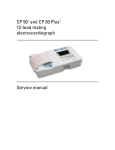
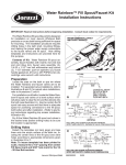
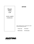
INSTRUCTIONS
REV. 3-27-00
-J00835
®
Kit Number 77165-98
1998 FLHT/C CRUISE CONTROL KIT
GENERAL
This cruise control kit is designed for installation on 1998 and
later FLHT/C model motorcycles.
2.
Remove battery, left saddlebag, left sidecover, fuel tank,
and air cleaner assembly following instructions in
applicable Service Manual.
3.
See Figure 1. Identify mounting holes for cruise control
module on left side of battery box.
4.
See Service Parts illustration. Place grommets (6)
through holes shown in Figure 1 with large diameters on
inside of battery box.
See Service Parts for kit contents.
1WARNING
Harley-Davidson, Inc. recommends that this kit be
installed by a Harley-Davidson authorized dealer.
Improper installation could cause cruise control
malfunction, loss of control, and death or serious injury.
Service Manual Required
This Instruction Sheet refers the installer to the appropriate
FLT Service Manual for many procedures. Therefore, HarleyDavidson recommends that you do not attempt to install this
kit without having a copy of the FLT Service Manual applicable
to your vehicle.
NOTE
A Service Manual for your vehicle is available from your
Harley-Davidson dealer.
NOTE
The cruise cable will be installed on the cruise module in the
kit. If cable is removed, refer to applicable Service Manual for
correct reinstallation procedure.
5.
See Figure 3. While feeding cruise cable and adjuster
through hole in frame cross member, place cruise module
(1) in position shown.
6.
See Service Parts illustration. Install three flange nuts (17)
to secure cruise control module to box. Tighten nuts to 911 ft-lbs.
7.
From left side of motorcycle, route the cruise cable under
rear cylinder spark plug wire; forward, above top engine
stabilizer; and then down between cylinder heads and
right to carburetor.
8.
Follow Service Manual instructions to connect cruise
cable to carburetor.
9.
See Figure 2. Install wire harness retainer on cruise cable
and insert barb on clip into hole in frame. On Calif.
models, remove EVAP hose from cable clip and secure
hose with T-stud cable strap from kit in location shown.
INSTALLATION
1.
Review the “CRUISE CONTROL-Ultra MODELS” section
in the applicable FLT Service Manual before attempting to
install this kit.
NOTE
When connector numbers such as “[22A]” are referenced, they
identify connectors on wiring diagrams. Wiring diagrams are
located at the rear of the FLT Service Manual, on Wiring
Diagram Wallcharts, and in the Electrical Troubleshooting
Manual.
Idle Control Cable - Throttle Adjusting Screw
1.
Remove outer fairing following the applicable Service
Manual procedures.
2.
Disconnect stock idle control cable from carburetor
following instructions in Service Manual.
To avoid personal injury, do not smoke or allow open
flame or sparks anywhere in the area when working on
fuel system components. Gasoline is extremely
flammable and highly explosive under certain
conditions.
3.
Remove upper and lower right handlebar switch housing
screws.
4.
See Figure 4. Loosen throttle adjusting screw (1), and
remove friction spring (2) from groove in switch housing
(3).
1WARNING
5.
Remove retaining ring (4) from throttle adjusting screw (1)
and remove spring (5) and screw (1) from lower switch
housing (3).
6.
Plug throttle adjusting screw tapped hole in switch
housing (3) with pop rivet (6) and washer (7).
7.
Discard throttle adjusting screw, spring, retaining ring and
friction spring.
Cruise Control Module
1WARNING
To avoid accidental start-up of motorcycle, and possible
personal injury, disconnect the battery cables (negative
cable first) before performing any of the following
procedures. If the positive cable should contact ground
with the negative cable installed, the resulting sparks
may cause a battery explosion resulting in death or
serious injury.
1 of 8
i00998
F1419
Cruise module
mounting holes
T-stud for attaching EVAP
hose on Calif. models
Left side of
battery box
Figure 1. Cruise Module Mounting Holes
8.
Remove idle control cable brass ferrule from notch in
throttle grip. Retain brass ferrule for use later.
9.
Follow instructions in Section 2 of applicable Service
Manual to remove stock idle cable.
10. Follow instructions in Section 8, CRUISE CONTROLTHROTTLE CABLES, of applicable Service Manual and
install the new idle control cable from kit.
11. Do not adjust throttle and idle cables now. The throttle,
idle, and cruise cables will be adjusted after cruise
control harness installation.
Rear cylinder head
Cable clip
Figure 2. Attaching Cruise Cable Adjuster (Left Side View)
12. See Figure 5. Install the coiled tubing on the throttle cable
from front to rear. Open the split in the tubing, place the
tubing on the cable and feed tubing back through the
frame clamp until the tubing end contacts the induction
module cable guide.
i00742
®
2
1
4
3
1.
2.
3.
4.
Cruise module (old style shown)
Cruise cable
Connector latch
Cruise connector [17B]
Figure 3. Mounting Cruise Module
-J00835
2 of 8
Cruise Control ON/OFF Switch
i00295
2
NOTE
Cruise control ON/OFF switch installs in fairing cap right side,
next to ACC switch. Removal of ignition switch on International
models requires removing switch position decal and tamperproof plugs. See applicable Service Manual for detailed
REMOVAL/INSTALLATION instructions.
1.
2.
4
See Figure 6. Remove ignition switch and fairing cap
according to Service Manual instructions.
3
See Figure 7. Remove screws (1) holding switch bracket
(2) in place.
3.
Remove switch hole plug.
4.
Install cruise control switch wires through bracket. Place
cruise switch in opening of bracket and engage tabs on
switch into slots on bracket latches.
7
5
CAUTION
Make certain socket terminals are correctly oriented in the
next step. The slot and crimp tails must face toward the
release button on the socket housing. Any other
orientation will not allow terminal to lock in position.
5.
Refer to FAIRING CAP SWITCHES in applicable Service
Manual. Open secondary lock on 12-place socket housing
[105B] located behind the fairing cap. Connect the
Orange/Violet wire to cavity number 4. Connect the
Red/Green wire to cavity number 5. Connect one
Black/Green wire to cavity number 12 in the 12-place
socket housing. Terminate the 2nd Black/Green wire, it is
not used.
1
1. Throttle adjust. screw
2. Friction spring
3. Lower right switch
housing
4.
5.
6.
7.
6
Retaining ring
Spring
Pop rivet
Washer
Figure 4. Throttle Adjusting Screw and Tapped Hole
6.
Close secondary lock on socket housing.
7.
Place Accessory and Cruise switches in fairing cap
openings. Install screws holding switch bracket.
NOTE
Do not install fairing cap or ignition switch now.
i00303
Cruise control harness
Throttle cable
Roll-off switch wires
inboard of throttle &
idle cables
Coiled tubing
Idle cable
Roll-off switch
wire connections
Figure 5. Throttle / Idle Cable and Roll-off Switch Configuration
-J00835
3 of 8
5502
Ignition Switch
Location
Fairing Switches
Connector [105B]
Fairing Cap
3.
Insert switch (6) with side having two tabs (7) positioned
as shown.
4.
Press switch (6) into escutcheon (4) until it latches into
position.
5.
Install speednut (8), place actuator (9) on switch rod and
press until actuator pins enter holes in switch tabs (10).
Set/Resume Switch Attachment to Handlebar Clamp
1. Cut the cable strap securing harnesses to right handlebar.
Switch Hole
Plug
2.
Route the Set/Resume harness along the handlebar and
forward of the inner fairing.
3.
Replace cable strap with one from kit.
4.
See Figure 8. Attach handlebar clamp to master cylinder
with the stock washers and two 1/4 -20 x 1-5/8 in. hex
socket button head screws from kit.
Figure 6. On / Off Switch Location, 1996 and Later
Set/Resume Switch Placement Into Handlebar Clamp
CAUTION
Do not disconnect or remove the switch housing
assembly without first placing a 5/32 inch thick cardboard
insert or cable strap eyelet between the brake lever and
lever bracket. Housing removal without an insert may
result in damage to the rubber boot and plunger of the
front brake light switch.
1.
See Figure 9. Remove the two screws and washers (1)
that secure the master cylinder clamp (2) and master
cylinder (3) to the handlebar and remove master cylinder
clamp (2). Discard the two screws and retain the washers
for use later.
2.
Remove from the kit and insert the escutcheon (4) into
the Set/Resume handlebar clamp (5).
Set/Resume Switch Electrical Connections
1. Cut connectors off ends of Blue/Black wires. Following
instructions in Service Manual under “Deutsch Electrical
Connectors”, crimp sockets (P/N 72191-94) onto each
wire end.
2.
Install Set/Resume switch wires into cavities 11 and 12 of
connector [22] as follows (see Figure 11 for connector
location):
See Figure 10. Remove the connector’s secondary
locking wedge. Grasp each crimped pin approximately 1
inch behind the contact barrel. Gently push pins through
holes in wire seal into their respective locations shown in
figure. Feed each pin into chamber until it “clicks” in place.
NOTE
If secondary locking wedge does not slide into position easily,
verify that all terminals are fully inserted into the housing.
i03056.eps
4
2
5
Speaker switch,
Ultra models
only
1
1
3
1. Screws (2)
2. Bracket
3. Socket housing [105B]
4. ACC switch
5. Cruise ON/OFF switch
Figure 7. Fairing Cap Switches (Ultra shown)
-J00835
4 of 8
3.
Connect power wire (O/V) of Set/Resume switch to
cigarette lighter as follows:
a. Cut connector off of end of O/V switch wire.
b. Follow procedures under Sealed Butt Splice
Connectors in Service Manual to connect O/W wire
in kit (item 30) to O/V wire of Set/Resume switch
using heat sealed connector in kit (item 5).
i00721a
Stock Washers and
1/4-20x1-5/8 Screws
from kit
Handlebar Clamp
Master Cylinder
c. Crimp 2-into-1 terminal in kit (item 29) onto end of
O/W wire and route wire to cigarette lighter (see
Figure 11 for location of lighter).
d. Remove existing O/W wire from back of cigarette
lighter, connect O/W from Set/Resume switch to
lighter, then reconnect original O/W wire to spade on
2-into-1 terminal.
Set/Resume
Switch
Cruise Control Harness Installation
1.
See Figure 12. The cruise control harness electrical
connections are shown.
Figure 8. Set / Resume Switch Attachment
2.
See Service Parts illustration. Install well nut (9) from kit
in hole. Install flat washer (10) and J-clamp (1) on screw.
Start screw into well nut. With the loop of the clamp
orientated at the top, tighten the clamp screw until snug.
NOTE
The 3-place socket connector containing orange/blue,
black/green and red/orange wires is only used on “Ultra”
models. Secure the 3-place connector to frame tube behind
cruise module with cable strap.
3.
Position the throttle control and idle control cables within
the J-clamp. Pinch or press ends of clamp closed to
contain cables.
3.
Install cable straps at the locations specified in the
CRUISE HARNESS, Installation procedure in the
Service Manual.
1.
Refer to the “CRUISE CONTROL - THROTTLE CABLES”
section in Section 8 of the applicable Service Manual and
adjust the throttle, idle control cable and cruise cables.
4.
Check that all wires and harnesses are located away from
hot or moving parts.
2.
Perform cruise cable adjustment. See “Cable Lash
Initialization” in applicable Service Manual.
2.
Refer to CRUISE HARNESS, Installation in applicable
Service Manual and install cruise control harness
following the instructions given.
Adjust Throttle, Idle, and Cruise Control Wire Harness
J-Clamp and Throttle Cable
1.
See Figure 13. Using the sharp edge of a knife, carefully
pull out the plastic plug in forward area of frame.
i00292
i00300
3
11
10
7
1
6
2
10
8
4
5
9
1.
2.
3.
4.
Screw and washer (2)
Master cylinder clamp
Master cylinder
Escutcheon
5.
6.
7.
8.
Handlebar clamp
Switch
Tabs (wire end of switch)
Speednut
9. Actuator
10. Tabs, actuator (2)
11. Harness
Figure 9. Installing Set / Resume Switch
-J00835
5 of 8
FINAL CHECK AND TEST RIDE
1.
2.
Check that all connections have been made and that all
wiring is properly secured with cable straps.
After tests are completed disconnect battery, negative
cable first.
5.
Install fuel tank, air cleaner backplate, air cleaner filter
and cover, left side cover, outer fairing and left saddlebag.
Perform the “Switch Diagnostic Sequence”, in the
applicable Service Manual, before installing fuel tank,
outer fairing, left side cover, and left saddlebag.
1WARNING
Always connect the positive battery cable first. If the
positive cable should contact ground with the negative
cable installed, the resulting sparks may cause a battery
explosion resulting in death or serious injury.
3.
4.
To perform the tests, reconnect battery, positive cable
first.
1WARNING
To avoid accidental start-up of motorcycle, and possible
personal injury, disconnect the battery cables (negative
cable first) before performing any of the following
procedures. If the positive cable should contact ground
with the negative cable installed, the resulting sparks
may cause a battery explosion resulting in death or
serious injury.
1WARNING
Always connect the positive battery cable first. If the
positive cable should contact ground with the negative
cable installed, the resulting sparks may cause a battery
explosion resulting in death or serious injury.
6.
Connect battery, positive cable first.
7.
Install seat.
1WARNING
After installing seat, pull upward on front of seat to be
sure it is locked in position. If seat is loose, it could shift
position during vehicle operation and startle the rider,
causing loss of control and death or serious injury.
8.
Refer to cruise control section in Owner’s Manual for
cruise control operating instructions.
9.
Test ride motorcycle and verify cruise control is operating
properly.
XLHDT
[22]
Wire seal
WIRE COLOR
White/blue
Blue/Black
H
SC
UT
DE
Locking
wedge
CAVITY
11
12
Figure 10. Set / Resume Switch Connections
i03023
Cruise harness to
interconnect
harness
connector [6]
Set/Resume
switch
connector [22]
Cigarette
lighter
Figure 11. Cruise Harness Connections At Inner Fairing
-J00835
6 of 8
i01062
12
11
10
9
8
7
6
5
4
3
2
1
PLUG
W/GN
W/BE
BE/BK
R/BE
PK
GN/R
O/V
R/GN
BE/BK
W/BE
V/Y
BK
O/V
R/BE
PK
GN/R
W/GN
PLUG
PLUG
R/GN
PLUG
CRUISE CONTROL
HARNESS
Part No. 77141-98
Figure 12. Electrical Connections
Steering head
i00302
Frame backbone
Plastic plug
Figure 13. Remove Plug From Frame
-J00835
7 of 8
®
Part No. 77165-98
Service Parts
Date 3/00
1998 Cruise Control Kit
sp77166-98
20
15
9
10
25
19
1
26
17
13
6
14
Item
1
2*
3*
4*
5
6
7*
8*
9
10
11*
12*
13
14
15
Description
Part No.
Clamp (J-type)
10003
Cable straps, 5 in. (11)
10039
Cable straps, 15 in. (3)
10073
T-stud clip/strap (CA models)
10133
Butt splice connector*
70585-93
Grommets (3)
11497
Screws, 1/4-20 x 1-5/8 in. (2)
4033
Handlebar/master cylinder clamp
with Set/Resume switch hsng
45043-89
Nut, well
5207
Washer, approx 5/8 in. O.D.
6047
Conduit, 1/4 in. x 12 in. long
63574-94
Washer, approx 3/8 in. O.D.
6717
Wire harness retainer
56073-83
Cruise Module
70989-98A
Cruise ON/OFF switch
71513-98
Item
16*
17
18*
19
20
21
22
23
24*
25
26
27*
28*
29*
30*
31*
32*
Description
Decal, ign. switch
Flange nuts (3)
Rivet, pop
Screw, machine truss
Cruise control wire harness
not used
not used
not used
Switch, Set/Resume
Idle control cable
Cruise cable
Plugs, lock (4) Int’l only
Wire harness retainer
2-into-1 wire terminal*
Wire, 16 in. long (O/W)
Terminal, socket (2)
Ring, retaining
Part No.
71537-96
7499
8625
933
70141-98
77163-94
56351-96
56372-98
90468-95
70345-84
9938
70652-99
72191-94
11193
*not shown in illustration
-J00835
8 of 8