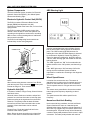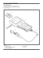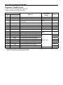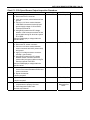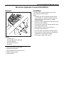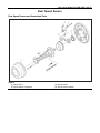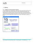
1
WORKSHOP MANUAL
NKR . NPR . NQR
ANTI-LOCK BRAKE SYSTEM
(ABS)
SECTION 5A4
HOME
ANTI-LOCK BRAKE SYSTEM (ABS) 5A4-1
SECTION 5A4
ANTI-LOCK BRAKE SYSTEM (ABS)
Service Precaution
CAUTION: Always use the correct fastener in the proper location. When you replace a fastener, use ONLY
the exact part number for that application. ISUZU will call out those fasteners that require a replacement
after removal. ISUZU will also call out the fasteners that require thread lockers or thread sealant. UNLESS
OTHERWISE SPECIFIED, do not use supplemental coatings (Paints, greases, or other corrosion inhibitors)
on threaded fasteners or fastener joint interfaces. Generally, such coatings adversely affect the fastener
torque and the joint clamping force, and may damage the fastener. When you install fasteners, use the
correct tightening sequence and specifications. Following these instructions can help you avoid damage to
parts and systems.
CONTENTS
PAGE
Service Precaution .......................................................................................................... 5A4 -1
General Description ........................................................................................................ 5A4 -5
System Components .................................................................................................. 5A4 -6
Electronic Hydraulic Control Unit (EHCU) ................................................................ 5A4 -6
Hydraulic Unit (HU) ..................................................................................................... 5A4 -6
ABS Warning Light ..................................................................................................... 5A4 -6
Wheel Speed Sensor .................................................................................................. 5A4 -6
Normal and Anti-lock Braking.................................................................................... 5A4 -6
Brake Pedal Travel...................................................................................................... 5A4 -7
Acronyms and Abbreviations .................................................................................... 5A4 -7
General Diagnosis ........................................................................................................... 5A4 -7
General Information.................................................................................................... 5A4 -7
ABS Service Precautions ........................................................................................... 5A4 -7
Computer System Service Precautions .................................................................... 5A4 -7
General Service Precautions ..................................................................................... 5A4 -8
Note on Intermittents.................................................................................................. 5A4 -8
Test Driving ABS Complaint Vehicles....................................................................... 5A4 -8
“ABS” Warning Light.................................................................................................. 5A4 -8
Normal Operation ....................................................................................................... 5A4 -8
Basic Diagnostic Flow Chart ..................................................................................... 5A4 -9
Basic Inspection Procedure....................................................................................... 5A4 -9
5A4-2 ANTI-LOCK BRAKE SYSTEM (ABS)
Tech 2 Scan Tool ........................................................................................................ 5A4 -10
Tech 2 Features .......................................................................................................... 5A4 -11
Getting Started ............................................................................................................ 5A4 -11
Operating Procedure (For Example) ......................................................................... 5A4 -12
DTC Modes .................................................................................................................. 5A4 -13
DTC Information Mode ............................................................................................... 5A4 -13
Plotting Snapshot Graph............................................................................................ 5A4 -14
Plotting Graph Flow Chart (Plotting graph after obtaining vehicle information) .. 5A4 -15
Flow Chart for Snapshot Replay (Plotting Graph) ................................................... 5A4 -16
Tech 2 Data Display .................................................................................................... 5A4 -17
Special Function ......................................................................................................... 5A4 -17
EHCU Connector Pin-out Checks.............................................................................. 5A4 -21
Circuit Diagram ........................................................................................................... 5A4 -22
Connector List ............................................................................................................ 5A4 -26
Part Location............................................................................................................... 5A4 -29
Symptom Diagnosis ........................................................................................................ 5A4 -30
Chart A-1 ABS Works Frequently But Vehicle Does Not Decelerate...................... 5A4 -30
Chart TA-1 ABS Works Frequently But Vehicle
Does Not Decelerate (Use TECH 2) ........................................................................... 5A4 -30
Chart A-2 Uneven Braking Occurs While ABS Works ............................................. 5A4 -31
Chart A-3, TA-3 The Wheels Are Locked................................................................... 5A4 -31
Chart A-4 Brake Pedal Feed Is Abnormal ................................................................. 5A4 -32
Chart A-5, TA-5 Braking Sound (From Hydraulic Unit)
Is Heard While Not Braking........................................................................................ 5A4 -33
Diagnostic Trouble Codes .............................................................................................. 5A4 -34
Diagnosis By “ABS” Warning Light Illumination Pattern ............................................ 5A4 -35
Diagnostic Trouble Codes (DTCs)............................................................................. 5A4 -35
Chart B-1-1 With the key in the ON position (Before starting the engine).
Warning light (W/L) is not activated. ......................................................................... 5A4 -39
Chart 1 (DTC 13/C0213) Vehicle Type Error.............................................................. 5A4 -40
Chart 2 (DTC 14/C0214) Low Power Voltage of
Rear Sensor or EHCU Abnormality ........................................................................... 5A4 -40
Chart 3 (DTC 15/C0215) Low Power Voltage OUT of Range ................................... 5A4 -41
Chart 4 (DTC 25/C0225) Exhaust Brake Cut Circuit Abnormality ........................... 5A4 -42
Chart 5 (DTC 33/C0233) Motor Drive Circuit Abnormality ....................................... 5A4 -42
ANTI-LOCK BRAKE SYSTEM (ABS) 5A4-3
Chart 6 (DTC 34/C0234) Abnormal Motor Rotation .................................................. 5A4 -42
Chart 7 (DTC 41/C0241) Solenoid Valve Power Supply Abnormality ..................... 5A4 -43
Chart 8 (DTC 43, 45/C0243, C0245) Solenoid Valve Circuit Abnormality ............... 5A4 -43
Chart 9 (DTC 51/C0251) FL Speed Sensor Circuit Abnormality .............................. 5A4 -43
Chart 10 (DTC 52/C0252) FR Speed Sensor Circuit Abnormality............................ 5A4 -43
Chart 11 (DTC 53/C0253) RL Speed Sensor Circuit Abnormality............................ 5A4 -44
Chart 12 (DTC 54/C0254) RR Speed Sensor Circuit Abnormality ........................... 5A4 -45
Chart 13 (DTC 61/C0261) Abnormal FL Speed Sensor Signal................................. 5A4 -46
Chart 14 (DTC 62/C0262) Abnormal FR Speed Sensor Signal ................................ 5A4 -48
Chart 15 (DTC 63/C0263) Abnormal RL Speed Sensor Signal ................................ 5A4- 50
Chart 16 (DTC 64/C0264) Abnormal RR Speed Sensor Signal................................ 5A4- 51
Chart 17 (DTC 65/C0265) Tire Size Error................................................................... 5A4- 52
Unit Inspection Procedure.............................................................................................. 5A4- 53
Chart C-1-1 FL Speed Sensor Output Inspection Procedure .................................. 5A4- 53
Chart C-1-2 FR Speed Sensor Output Inspection Procedure.................................. 5A4- 54
Chart C-1-3 RL Speed Sensor Output Inspection Procedure.................................. 5A4- 55
Chart C-1-4 RR Speed Sensor Output Inspection Procedure ................................. 5A4- 57
Chart TC-1 Sensor Output Inspection Procedure (Use TECH 2) ............................ 5A4- 58
Electronic Hydraulic Control Unit (EHCU)..................................................................... 5A4- 59
Removal....................................................................................................................... 5A4- 59
Installation................................................................................................................... 5A4- 59
Front Speed Sensor ........................................................................................................ 5A4- 60
Front Speed Sensor and Associated Parts .............................................................. 5A4- 60
Removal....................................................................................................................... 5A4- 60
Inspection and Repair ................................................................................................ 5A4- 60
Installation................................................................................................................... 5A4- 60
Front Speed Sensor Rotor.............................................................................................. 5A4- 61
Front Speed Sensor Rotor and Associated Parts.................................................... 5A4- 61
Removal....................................................................................................................... 5A4- 61
Inspection and Repair ................................................................................................ 5A4- 62
Installation................................................................................................................... 5A4- 62
Rear Speed Sensor ......................................................................................................... 5A4- 63
Rear Speed Sensor and Associated Parts................................................................ 5A4- 63
Removal....................................................................................................................... 5A4- 64
Inspection and Repair ................................................................................................ 5A4- 64
5A4-4 ANTI-LOCK BRAKE SYSTEM (ABS)
Installation................................................................................................................... 5A4- 64
Rear Speed Sensor Rotor ............................................................................................... 5A4- 65
Rear Speed Sensor Rotor and Associated Parts ..................................................... 5A4- 65
Removal....................................................................................................................... 5A4- 65
Inspection and Repair ................................................................................................ 5A4- 65
Installation................................................................................................................... 5A4- 65
Special Tools ................................................................................................................... 5A4- 67
ANTI-LOCK BRAKE SYSTEM (ABS) 5A4-5
General Description
determine when a wheel is about to stop turning and
adjust brake pressure to maintain best braking.
This system helps the drive maintain greater control of
the vehicle under heavy braking conditions.
The Anti-lock Brake System (ABS) works on all four
wheels. A combination of wheel speed sensor and
Electronic Hydraulic Control Unit (EHCU) can
9 ABS
6 DIAG
TO EHCU
CAB
10
ENGINE CONTROLLER
OR
EXH BRAKE CUT RELAY
4
TO EHCU
5
7
TO EHCU
ELECTRONIC HYDRAULIC
3
EHCU CONTROL UNIT(EHCU)
HYDRAULIC UNIT(HU)
1
2
4
5
8
Legend
(1) Hydraulic Line
(2) Electronic Line
(3) Electronic Hydraulic Control Unit (EHCU)
(4) Front Wheel Speed Sensor
(5) Rear Wheel Speed Sensor
(6) Diagnosis Connector
(7)
(8)
(9)
(10)
Load Sensing Proportioning Valve (LSPV)
Battery
ABS Warning Light
Brake Switch
5A4-6 ANTI-LOCK BRAKE SYSTEM (ABS)
System Components
ABS Warning Light
The Anti-lock Brake System consists of a Electronic
Hydraulic Control Unit (EHCU), four Wheel Speed
Sensors and Warning Light.
Electronic Hydraulic Control Unit (EHCU)
The EHCU consists of Electronic Brake Control
Module (EBCM) and Hydraulic Unit (HU).
The EHCU is located at the frame side, in front of rear
spring bracket.
The EHCU consists of ABS control circuits, fault
detector, and a fail-safe. It drives the hydraulic unit
according to the signal from each sensor, cancelling
ABS to return to normal braking when a malfunction
has occurred in the ABS.
The EHCU is self-diagnosing function which can
indicate faulty circuits during diagnosis.
CONNECTOR
EHCU
Tang lock
Push
Lever
Move lever outside
Vehicles equipped with the Anti-lock Brake System
has an amber “ABS” warning light in the instrument
panel. The “ABS” warning light will illuminate if a
malfunction in the Anti-lock Brake System is detected
by the Electronic Hydraulic Control Unit (EHCU). In
case of an electronic malfunction, the EHCU will turn
“ON” the “ABS” warning light and disable the Anti-lock
braking function.
The “ABS” light will turn “ON” for 2 seconds after the
ignition switch is to the “ON” position, and then will go
out.
If the “ABS” light comes “ON” and stays “ON” while
driving, the Anti-lock Brake System should be
inspected for a malfunction according to the diagnosis
procedure.
Wheel Speed Sensor
NOTE:
When disconnecting harness connector from EHCU,
push the tang lock of the connector (
portion) and
release the tang lock. Then move the lever.
Hydraulic Unit (HU)
It consists of a Motor, Plunger Pump, Solenoid Valves
and Check Valve.
Solenoid Valves: Reduces or holds the caliper fluid
pressure for each front disc brake or both rear drum
brakes according to the signal sent from the EHCU.
Reservoir: Temporarily holds the brake fluid that
returns from the front and rear wheel brake so that
pressure of front wheel brake can be reduced
smoothly.
Plunger Pump: Feeds the brake fluid held in the
reservoir to the master cylinder.
Motor: Drives the pump according to the signal from
EHCU. Check Valve: Controls the brake fluid flow.
It consists of a sensor and a rotor. The sensor is
attached to the knuckle on the front wheels and to the
bracket on the brake back plate on the rear wheels.
The front speed sensor is coil type and rear is Hall IC
type.
The sensor rotors press-fitted to front and rear wheel
hubs output pulse frequency depending on wheel
rotation.
The speed sensors find vehicle speed from its
frequency.
Normal and Anti-lock Braking
Under normal driving conditions, the Anti-lock Brake
System functions the same as a standard power
assisted brake system. However, with the detection of
wheel lock-up, a slight bump or kick-back will be felt in
the brake pedal. This pedal “bump” will be followed by
a series of short pedal pulsations which occurs in rapid
succession. The brake pedal pulsation will continue
ANTI-LOCK BRAKE SYSTEM (ABS) 5A4-7
until there is no longer a need for the anti-lock function
or until the vehicle is stopped. A slight ticking or
popping noise may be heard during brake applications
when the Anti-lock features is being used.
When the Anti-lock feature is being used, the brake
pedal may rise even as the brakes are being applied.
This is also normal. Maintaining a consist force on the
pedal will provide the shortest stopping distance.
Brake Pedal Travel
Vehicles equipped with the Anti-lock Brake System
may be stopped by applying normal force to the brake
pedal. Although there is no need to push the pedal
beyond the point where it stops or holds the vehicle, by
applying more force the pedal will continue to travel
toward the floor.
This extra brake pedal travel is normal.
Acronyms and Abbreviations
Several acronyms and abbreviations are commonly
used throughout this section:
ABS
Anti-lock Brake System
CKT
Circuit
DLC
Data Link Connector
DTC
Diagnostic Trouble Code
DVM
Digital Volt Meter (High Impedance Multimeter)
EHCU
Electronic Hydraulic Control Unit
FL
Front Left
FR
Front Right
GEN
Generator
HU
Hydraulic Unit
MV
Millivolts
RL
Rear Left
RR
Rear Right
RPS
Revolution per Second
SW
Switch
VDC
Volts DC
VAC
Volts AC
W/L
Warning Light
WSS
Wheel Speed Sensor
General Diagnosis
General Information
ABS malfunction can be classified into two types,
those which can be detected by the ABS warning light
and those which can be detected as a vehicle
abnormality by the driver.
In either case, locate the fault in accordance with the
“BASIC DIAGNOSTIC FLOWCHART” and repair.
Please refer to Section 5A for the diagnosis of
mechanical troubles such as brake noise, brake judder
(brake pedal or vehicle vibration felt when braking),
uneven braking, and parking brake trouble.
ABS Service Precautions
Required Tools and Items:
• Box Wrench
• Brake Fluid
• Special Tool
Some diagnosis procedures in this section require the
installation of a special tool.
5-8840-0285-0 (J-39200) High Impedance
Multimeter
When circuit measurements are requested, use a
circuit tester with high impedance.
Computer System Service Precautions
The Anti-lock Brake System interfaces directly with the
Electronic Hydraulic Control Unit (EHCU) which is a
control computer that is similar in some regards to the
Engine Control Module. These modules are designed
to withstand normal current draws associated with
vehicle operation. However, care must be taken to
avoid overloading any of the EHCU circuits. In testing
for opens or shorts, do not ground or apply voltage to
any of the circuits unless instructed to do so by the
appropriate diagnostic procedure. These circuits
should only be tested with a high impedance
multimeter 5-8840-0285-0 (J-39200) or special tools
as described in this section. Power should never be
removed or applied to any control module with the
ignition in the “ON” position. Before removing or
connecting battery cables, fuses or connectors, always
turn the ignition switch to the “OFF” position.
5A4-8 ANTI-LOCK BRAKE SYSTEM (ABS)
General Service Precautions
The following are general precautions which should be
observed when servicing and diagnosing the Anti-lock
Brake System and/or other vehicle systems. Failure to
observe these precautions may result in Anti-lock
Brake System damage.
• If welding work is to be performed on the vehicle
using an electric arc welder, the EHCU connector
should be disconnected before the welding
operation begins.
• The EHCU connector should never be connected
or disconnected with the ignition “ON”.
• The EHCU is not separately serviceable and must
be replaced as assemblies. Do not disassemble
any component which is designated as nonserviceable in this Section.
• If only rear wheels are rotated using jacks or drum
tester, the system will diagnose a speed sensor
malfunction and the “ABS” warning light will
illuminate. But actually no trouble exists. After
inspection stop the engine once and re-start it, then
make sure that the “ABS” warning light does not
illuminate.
If the battery has been discharged
The engine may stall if the battery has been
completely discharged and the engine is started via
jumper cables. This is because the Anti-lock Brake
System (ABS) requires a large quantity of electricity. In
this case, wait until the battery is recharged, or set the
ABS to a non-operative state by removing the fuse for
the ABS. After the battery has been recharged, stop
the engine and install the ABS fuse. Start the engine
again, and confirm that the ABS warning light does not
light.
Note on Intermittents
As with virtually any electronic system, it is difficult to
identify an intermittent failure. In such a case
duplicating the system malfunction during a test drive
or a good description of vehicle behavior from the
customer may be helpful in locating a “most likely”
failed component or circuit. The symptom diagnosis
chart may also be useful in isolating the failure. Most
intermittent problems are caused by faulty electrical
connections or wiring. When an intermittent failure is
encountered, check suspect circuits for:
• Suspected harness damage.
• Poor mating of connector halves or terminals not
fully seated in the connector body (backed out).
• Improperly formed or damaged terminals.
Test Driving ABS Complaint Vehicles
In case that there has been an malfunction in the
lighting pattern of “ABS” warning light, the fault can be
located in accordance with the “DIAGNOSIS BY “ABS”
WARNING LIGHT ILLUMINATION PATTERN”. In
case of such trouble as can be detected by the driver
as a vehicle symptom, however, it is necessary to give
a test drive following the test procedure mentioned
below, thereby reproducing the symptom for trouble
diagnosis on a symptom basis:
1. Start the engine and make sure that the “ABS” W/L
goes OFF. If the W/L remains ON, it means that
the Diagnostic Trouble Code (DTC) is stored.
Therefore, read the code and locate the fault.
2. Start the vehicle and accelerate to about 30km/h
(19 mph) or more.
3. Slowly brake and stop the vehicle completely.
4. Then restart the vehicle and accelerate to about 40
km/h (25 mph) or more.
5. Brake at a time so as to actuate the ABS and stop
the vehicle.
6. Be cautious of abnormality during the test. If the
W/L is actuated while driving, read the DTC and
locate the fault.
7. If the abnormality is not reproduced by the test,
make best efforts to reproduce the situation
reported by the customer.
8. If the abnormality has been detected, repair in
accordance with the “SYMPTOM DIAGNOSIS”.
NOTE:
• Be sure to give a test drive on a wide, even road
with little traffic.
• If an abnormality is detected, be sure to suspend
the test and start trouble diagnosis at once.
“ABS” Warning Light
When ABS trouble occurs and actuates when possible
the “ABS” warning light, the trouble code
corresponding to the trouble is stored in the EHCU.
Only the ordinary brake system is available when the
ABS is turned OFF. When the “ABS” warning light is
actuated, if the starter switch is set ON after setting it
OFF once, the EHCU checks up on the entire system
and, if there is no abnormality, judges ABS to work
currently and the warning light works normally even
though the trouble code is stored.
NOTE: Illumination of the “ABS” warning light indicates
that anti-lock braking is no longer available. Power
assisted braking without anti-lock control is still
available.
Normal Operation
“ABS” Warning Light
When the ignition is first moved from “OFF” to “ON”,
the amber “ABS” warning light will turn “ON” for 2
seconds and will turn “OFF”.
ANTI-LOCK BRAKE SYSTEM (ABS) 5A4-9
Basic Diagnostic Flow Chart
Step
1
2
3
4
5
6
Action
1. Customer complaint.
2. Questioning to customer.
3. Basic inspection (Refer to “Basic inspection procedure”)
Using TECH 2?
Make sure of DTC by TROUBLE CODE.
Is EHCU including DTC?
Check if the DTC is stored.
Is EHCU including DTC?
Test drive.
Is W/L lit?
1. Repair of faulty part.
2. Elimination of DTC.
3. Inspection of “ABS” W/L illumination pattern with ignition
SW “ON”.
4. Test drive.
Does repeat trouble?
1. Reconnect all components and ensure all components
are properly mounted.
2. Clear diagnostic trouble code.
Was this step finished?
Yes
Go to Step 2
No
Go to Step 3
Go to Step 5
Go to Step 4
Go to Step 5
Go to Step 4
Go to Step 5
Trouble diagnosis
based on symptom
(Refer to
“SYMPTOM
DIAGNOSIS”) Go
to Step 5
Go to Step 6
Repeat the
diagnosis of the
symptom or DTC
appears again Go
to Step 1
Finished
Go to Step 6
Yes
Go to Step 2
No
Replenish with
fluid.
Go to Step 2
Go to Step 3
Basic Inspection Procedure
1. Basic Inspection of Service Brake
Step
Action
1
Is the fluid level normal?
2
Does fluid leak?
3
Is the booster functioning normal?
Repair.
Go to Step 3
Go to Step 4
4
Is the pad and rotor normal?
Go to Step 5
5
Reconnect all components and ensure all components are
properly mounted.
Was this step finished?
2. Ground Inspection
Step
Action
1
Are ABS-related ground points ok?
2
Reconnect all components and ensure all components are
properly mounted.
Was this step finished?
Finished
Yes
Go to Step 2
Finished
Repair.
Go to Step 4
Repair.
Go to Step 5
Go to Step 5
No
Repair.
Go to Step 2
Go to Step 2
5A4-10 ANTI-LOCK BRAKE SYSTEM (ABS)
Tech 2 Scan Tool
From 98 MY, Isuzu dealer service departments are
recommended to use Tech 2. Please refer to Tech 2
scan tool user guide.
Legend
(1) PCMCIA Card
(2) RS 232 Loop Back Connector
(3) SAE 16/19 Adapter
(4) DLC Cable
(5) Tech-2
ANTI-LOCK BRAKE SYSTEM (ABS) 5A4-11
Tech 2 Features
1. Tech 2 is a 12 volt system. Do not apply 24 volt.
2. After connecting and/or installing the Vehicle
Communications Interface (VCI) module, PCMCIA
card and DLC connector to the Tech 2, connect
the tool to the vehicle DLC.
3. Make sure the Tech 2 is powered OFF when
removing or installing the PCMCIA card.
4. The PCMCIA card has a capacity of 10 Megabytes
which is 10 times greater than the memory of the
Tech 1 Mass Storage Cartridge.
5. The Tech 2 has the capability of two snapshots.
6. The PCMCIA card is sensitive to magnetism and
static electricity, so care should be taken in the
handling of the card.
7. The Tech 2 can plot a graph when replaying a
snapshot.
8. Always return to the Main Menu by pressing the
EXIT key several times before shutting down.
9. To clear Diagnostic Trouble Codes (DTCs), open
Application Menu and press “F1: Clear DTC Info”.
Getting Started
• Before operating the Isuzu PCMCIA card with the
Tech 2, the following steps must be performed:
1. The Isuzu 2000 Model Year System PCMCIA card
(1) inserts into the Tech 2 (5).
2. Connect the SAE 16/19 adapter (3) to the DLC
cable (4).
3. Connect the DLC cable to the Tech 2 (5).
4. Make sure the vehicle ignition is off.
5. Connect the Tech 2 SAE 16/19 adapter to the
vehicle DLC.
6. Turn on the vehicle ignition.
7. Power the Tech 2 ON and verify the Tech 2 power
up display.
Tech
2
Press [ENTER] to continue.
Software Version: X.XXX
NOTE: The RS232 Loop back connector is only to use
for diagnosis of Tech 2. Refer to user guide of the
Tech 2.
5A4-12 ANTI-LOCK BRAKE SYSTEM (ABS)
Operating Procedure (For Example)
The power up screen is displayed when you power up
the tester with the Isuzu systems PCMCIA card. Follow
the operating procedure below.
Tech
2
Press [ENTER] to continue.
Software Version: X.XXX
Vehicle Identification
Select one of the following
Vehicle Type (s)
(UE) Rodeo/Amigo, Wizard/MU
(TF ) LUV
(N∗) ELF, NPR, NQR
(Off-Road) Industrial Engine
3/4
(N∗) ELF, NPR, NQR
(N∗ENTER)
System Selection Menu
( 1 ) 2 0 0 1 ( N∗ ) E L F , N P R , N Q R
F0: Engine
F1: Chassis
(ENTER)
F2: Body
Main Menu
F0: Diagnostics
F1: Code Index
(F2 ENTER)
F2: View Capture Data
F3: Tool Options
Vehicle Identification
F4: Download / Upload Help
Select one of the following
Chassis
ABS
(F0)
Vehicle Identification
Select one of the following
Model Year(s)
(1) 2001
(Y) 2000
(X) 1999
(W) 1998
(1) 2001
1/2
ABS
(ABS/ASR ENTER)
1/4
(2000, ENTER)
ANTI-LOCK BRAKE SYSTEM (ABS) 5A4-13
Menu
• The following table shows which functions are used
for the available equipment versions.
Diagnostic Trouble Codes
F0: Read DTC Info Ordered By Priority
F1: Clear DTC Information
Chassis
(Y) 2000 (N∗) ELF, NPR, NQR
Electronic System: ABS
Partnumber
Identifier
8972521653
00(2WD)
20(4WD)
40(ABS/ASR)
60(12V vehicle)
F2: DTC Information
F3: Clear & Reset Vehicle Type
Partnumer
The following is a brief description of each of the sub
menus in DTC Info and DTC. The order in which they
appear here is alphabetical and not necessarily the
way they will appear on the Tech 2.
Confirm
DTC Modes
DTC Information Mode
Chassis
F0: Diagnostic Trouble Codes
F1: Data Display
F2: Snapshot
F3: Actuator Test
There are two options available in Tech 2 DTC mode
to display the enhanced information available. After
selecting DTC, the following menu appears.
• DTC Info
• Clear Info
Use the DTC info mode to search for a specific type of
stored DTC information. There are two choices. The
service manual may instruct the techinician to test for
DTCs in a certain manner. Always follow published
service procedures.
5A4-14 ANTI-LOCK BRAKE SYSTEM (ABS)
When CODE “13” is displayed (Vehicle Type Error)
Step
Action
1
Check harness.
Is it okay?
Diagnostic Trouble Codes
Value(s)
-
Yes
Erase vehicle
type with TECH
2 and reread
harness
information.
No
Replace the
harness.
Clear & Reset Vehicle Type
F0: Read DTC Info
F1: Clear DTC Info
Do you want clear &
F2: DTC Info
Reset Vehicle Type?
(F3: ENTER)
YES
NO
YES: Clear vehicle type and reread vehicle harness
information.
NO: Return
DTC Status
Current Diagnostic Trouble Codes
This selection will display all DTCs that have failed
during the present ignition cycle.
History Diagnostic Trouble Codes
This selection will display only DTCs that are stored in
the EHCU’s history memory.
Plotting Snapshot Graph
This test selects several necessary items from the
data list to plot graphs and makes data comparison on
a long term basis. This test can check ABS
performance and defect by graphing wheel speed
differences between right and left sides, and front and
rear sides obtained from the ABS data list menu.
For trouble diagnosis, you can collect graphic data
(snap shot) directly from the vehicle.
You can replay the snapshot data as needed.
Therefore, accurate diagnosis is possible, even though
the vehicle is not available.
ANTI-LOCK BRAKE SYSTEM (ABS) 5A4-15
Plotting Graph Flow Chart (Plotting graph after obtaining vehicle information)
5A4-16 ANTI-LOCK BRAKE SYSTEM (ABS)
Flow Chart for Snapshot Replay (Plotting Graph)
ANTI-LOCK BRAKE SYSTEM (ABS) 5A4-17
Tech 2 Data Display
Special Function
Use the Tech 2 data Values only after the ABS
Diagnostic System Check has been completed, no
DTC(s) were noted, and you have determined that the
on-board diagnostics are functioning properly. Tech 2
values from a properly-running engine may be used for
comparison with the engine you are diagnosing.
There are 12 different menus available for this test.
The state of each circuit can be tested by using these
menus. Especially when DTC cannot be detected, a
faulty circuit can be diagnosed by testing each circuit
by means of these menus.
Even when DTC has been detected, the circuit tests
using these menus could help discriminate between a
mechanical trouble and an electrical trouble.
In all cases test condition; Engine stops with the key
turned to the “ON” position. To be more specific, the
test is conducted with the brake pedal stepped on after
stepping once and releasing.
• Engine: Stop
• Ignition SW: ON
• Brake Pedal: ON-OFF-ON
If the Ignition SW was turned OFF or communication
was lost, make sure to apply the brake pedal ON-OFFON once again and then continue the test.
ABS Data
Ignition SW is “ON” position.
(For example)
Actuator Test
F0: ABS Relay Test
F1: Return Pump Relay Test
F2: Front Left Solenoid Valve Test
F3: Front Right Solenoid Valve Test
F4: Rear Left Solenoid Valve Test
F5: Rear Right Solenoid Valve Test
F6: ABS Check Light Test
F7: Exhaust Brake Cut Test
5A4-18 ANTI-LOCK BRAKE SYSTEM (ABS)
ABS Warning Lamp
Test condition: Engine stops with the key turned to the
“ON” position. To be more specific, the test is
conducted with the brake pedal stepped on after
stepping once and releasing.
• The circuit is normal if the warning light in the meter
panel comes on and goes out in accordance with
Tech 2’s instruction.
ABS Motor
Test condition: Engine stops with the key turned to the
“ON” position. To be more specific, the test is
conducted with the brake pedal stepped on after
stepping once and releasing.
Make sure of the working sound of the ABS motor.
The circuit is normal if the working sound of the ABS
motor is made in accordance with Tech 2’s instruction.
Actuator Test
Actuator Test
F0: ABS Relay Test
F1: Return Pump Relay Test
F2: Front Left Solenoid Valve Test
F3: Front Right Solenoid Valve Test
F4: Rear Left Solenoid Valve Test
F5: Rear Right Solenoid Valve Test
F7: Exhaust Brake Cut Test
ABS Relay
Test condition: Engine stops with the key turned to the
“ON” position. To be more specific, the test is
conducted with the brake pedal stepped on after
stepping once and releasing.
Make sure of the working sound of the ABS relay.
The circuit is normal if the working sound of the ABS
relay is made in accordance with Tech 2’s instruction.
F0: ABS Relay Test
F2: Front Left Solenoid Valve Test
F3: Front Right Solenoid Valve Test
F4: Rear Left Solenoid Valve Test
F5: Rear Right Solenoid Valve Test
F6: ABS Check Light Test
F7: Exhaust Brake Cut Test
Exhaust Brake Cut Relay
Test condition: Engine stops with the key turned to the
“ON” position. To be more specific, the test is
conducted with the brake pedal stepped on after
stepping once and releasing.
Make sure of the working sound of the exhaust brake
cut relay.
The circuit is normal if the working sound of the
exhaust brake cut relay is made in accordance with
Tech 2’s instruction.
Actuator Test
F1: Return Pump Relay Test
F2: Front Left Solenoid Valve Test
F3: Front Right Solenoid Valve Test
F4: Rear Left Solenoid Valve Test
F5: Rear Right Solenoid Valve Test
F6: ABS Check Light Test
F7: Exhaust Brake Cut Test
Actuator Test
F0: ABS Relay Test
F1: Return Pump Relay Test
F2: Front Left Solenoid Valve Test
F3: Front Right Solenoid Valve Test
F4: Rear Left Solenoid Valve Test
F5: Rear Right Solenoid Valve Test
F6: ABS Check Light Test
ANTI-LOCK BRAKE SYSTEM (ABS) 5A4-19
Hold Valve Test
Purpose: The purpose of this test is to detect brake
pipe and valve line harness wire wrong connections
and valve trouble.
This test will help you confirm the result of your repair
service including the removal/reinstallation of brake
pipe, valve line harness and valve.
Select a Iso Solenoid
from the Front Left Solenoid Valve Test
Function Menus.
Front Left Solenoid Valve Test
Actuator Test
Dump Solenoid
F0: ABS Relay Test
F1: Return Pump Relay Test
F3: Front Right Solenoid Valve Test
F4: Rear Left Solenoid Valve Test
F5: Rear Right Solenoid Valve Test
F6: ABS Check Light Test
F7: Exhaust Brake Cut Test
Test conditions: The ignition key is the “ON” position
with the four wheels lifted up. The brake pedal is
stepped on, released and stepped on again with the
parking brake released.
Test procedure:
1. Connect Tech 2 with the vehicle, and select
Special Function from the menus.
2. Select a Hold Valve Menu from the Special
Function Menus.
Actuator Test
F0: ABS Relay Test
F1: Return Pump Relay Test
F3: Front Right Solenoid Valve Test
F4: Rear Left Solenoid Valve Test
F5: Rear Right Solenoid Valve Test
F6: ABS Check Light Test
F7: Exhaust Brake Cut Test
3. Press the Hold Valve “ON” Soft Key with the brake
pedal stepped on.
4. Release the brake pedal.
5. Make sure that the Hold Valve “ON” aimed at by
Tech 2 and the wheel locked position are the
same. If different, check brake pipe, valve line
harness wiring and H/UNIT. Repair is needed if
abnormality is found.
6. Conduct Step 2 through Step 5 above on all the
four wheels.
CAUTION: When conducting this test, please
observe the following cautions.
1. Do not start the engine without fail.
2. Lift up the vehicle at the level floor.
• Secure a clearance from the floor surface
enough to allow the lifted tire to rotate.
3. Maintain the lift up.
4. Wipe the floor surface to remove water and oil
so that the surface may become unslippery.
5. Do not load the vehicle.
• When lifting up the vehicle, be sure to
observe the lifting up points. Refer to
vehicle lifting points in 0A section.
5A4-20 ANTI-LOCK BRAKE SYSTEM (ABS)
Release Valve Test
Purpose: The purpose of this test is to detect brake
pipe and valve line harness wire wrong connections
and valve trouble.
This test will help you confirm the result of your repair
service including the removal/reinstallation of brake
pipe, valve line harness and valve.
Select a Dump Solenoid
from the Front Left Solenoid Valve Test
Function Menus.
Front Left Solenoid Valve Test
Actuator Test
Iso Solenoid
F0: ABS Relay Test
F1: Return Pump Relay Test
F3: Front Right Solenoid Valve Test
F4: Rear Left Solenoid Valve Test
F5: Rear Right Solenoid Valve Test
F6: ABS Check Light Test
F7: Exhaust Brake Cut Test
Test conditions: The ignition key is in the “ON” position
with the four wheels lifted up. The brake pedal is
stepped on, released and stepped on again with the
parking brake released.
Test procedure:
1. Connect Tech 2 with the vehicle, and select
Special Function from the menus.
2. Select a Release Valve Menu from the Special
Function Menus.
Actuator Test
F0: ABS Relay Test
F1: Return Pump Relay Test
F3: Front Right Solenoid Valve Test
F4: Rear Left Solenoid Valve Test
F5: Rear Right Solenoid Valve Test
F6: ABS Check Light Test
F7: Exhaust Brake Cut Test
3. Press the Release Valve “ON” Soft Key with the
brake pedal stepped on.
4. Make sure that the Release Valve “ON” aimed at
by Tech 2 and the wheel released position are the
same. If different, check brake pipe, valve line
harness wiring and H/UNIT. Repair is needed if
abnormality is found.
5. Conduct Step 2 through Step 5 above on all the
four wheels.
CAUTION: When conducting this test, please
observe the following cautions.
1. Do not start the engine without fail.
2. Lift up the vehicle at the level floor.
• Secure a clearance from the floor surface
enough to allow the lifted tire to rotate.
3. Maintain the lift up.
4. Wipe the floor surface to remove water and oil
so that the surface may become unslippery.
5. Do not load the vehicle.
• When lifting up the vehicle, be sure to
observe the lifting up points. Refer to
vehicle lifting points in 0A section.
ANTI-LOCK BRAKE SYSTEM (ABS) 5A4-21
• Perform checks with high impedance digital
multimeter 5-8840-0285-0 (J-39200) or equivalent.
EHCU Connector Pin-out Checks
• Disconnect EHCU.
No.
1
Circuit to be Tested
EHCU Power Circuit
Key
Switch
Position
OFF
ON
Multimeter
Scale/Range
Measure
between Pin
VDC
VDC
3(+)-1(-)
3(+)-1(-)
OFF
VDC
2(+)-1(-)
OFF
VDC
24(+)-1(-)
Ω
Ω
VDC
1(+)-GND
23(+)-GND
7(+)-1(-)
2
EHCU Ground Circuit
3
EXHIN Circuit
OFF
OFF
ON
4
EXHOUT Circuit
ON
VDC
8(+)-1(-)
5
Brake Switch Signal
Circuit
OFF
OFF
VDC
VDC
8(+)-1(-)
16(+)-1(-)
OFF
VDC
16(+)-1(-)
ABS W/L Circuit
ON
VDC
6(+)-1(-)
FL Speed Sensor
OFF
OFF
OFF
VDC
kΩ
kΩ
6(+)-1(-)
10(+)-11(-)
10(+)-1(-)
OFF
VDC
10(+)-11(-)
OFF
OFF
kΩ
kΩ
32(+)-33(-)
32(+)-1(-)
OFF
VDC
32(+)-33(-)
6
7
8
FR Speed Sensor
Nominal Value
(24V Battery
Vehicle)
0-0.3V
9.5-16.5V
(16.5-34V)
9.5-16.5V
(16.5-34V)
9.5-16.5V
(16.5-34V)
Less than 0.01 Ω
Less than 0.01 Ω
9.5-16.5V
(16.5-34V)
9.5-16.5V
(16.5-34V)
0-0.3V
0-0.3V
9.5-16.5V
(16.5-34V)
9.5-16.5V
(16.5-34V)
0-0.3V
1-2kΩ
More than
1000kΩ
More than 200mV
1-2kΩ
More than
1000kΩ
More than 200mV
Note
Engine Run
Apply Brake
Pedal
Turn Wheel at
0.5RPS
Turn Wheel at
0.5RPS
5A4-22 ANTI-LOCK BRAKE SYSTEM (ABS)
Circuit Diagram-FOR 12VOLT
F-17
STOP LAMP
10A
3W
SW ; STOP LAMP
0.5G/Y
1
FL-4
ABS
60A
3R
RELAY ;
EXH.BRAKE
5W
MAIN
80A
8W 2
0.5G
2
3R
FL-1
8B
B-66
B-66
B-38
3W 1
5W
H-6
F-14
EXH.BRAKE
5 2B/R 15A
0.5LG
B-38
H-5
B-38
4
B-38
40
0.5LG/W
0.5W/L 2
RELAY;
CHARGE
FL-2
KEY SW
50A
1
2
J-16
J-16
RELAY ;
TAIL
0.3B
RELAY ;
EXH.B/CUT
(ABS)
SW ;
ENG.WARMING
0.3B
1
H-7
J-16
J-16
5
4
0.5LG/B
3W/B
P-5
3
J-16
KEY SW
OFF
0.5B
P-1
BATTERY
P-2
0.5LG/R
2
0.5LG/B
3
0.3B
1
0.3B
B-31
B-31
B-31
B-31
B-31
B-31
5
0.3B
6 0.5BR/R
4 0.5BR/R
0.3B
ACC
B
B-67
ON
B-67
3
0.5B/Y
F-12
3B/Y
GAUGE
BACK
10A
ST
0.5LG/B
METER
H-5
36
0.5B/Y
0.5B/Y
ABS
8
B-51
B-51
7
0.5B/Y
0.5LG/B
0.5B/Y
0.3W/V
2
0.5W
3W/B
0.5B/Y
5
3
B-69
B-35
4
B-35
2
J-50
SW ; NEUTRAL
(Neutral=ON)
1
0.5B/G
0.5LG/L
0.5LG/L
B-69
J-50
3
IND.LAMP ;
EXH.BRAKE
0.5LG/L 1
B-51
0.5LG/R
4
5
0.5BR/B
0.85B
3
0.5LG/B
J-18
2
2B
J-18
3
B-18
H-5
12
FRAME-LH (CENTER)
J-9
DIODE
SW ; CLUTCH
0.5LG/B 1
B-89
B-89
1
2 0.5LG/R
B-18
B-18
0.5B
0.5B
0.85B
B-1
B-7
10
J-18
2B
HEADLIGHT BRACKET (LH)
2
0.5B
17
RELAY ;
EXH.BRAKE
CONTROL
FRAME-LH (FRONT)
B-35
5
H-8
J-18
0.3B
B-52
B-35
3B 2
8
7
JOINT
B-29 CONNECTOR
0.5LG/W
0.3B
RELAY ;
ABS IND.
SW ; EXH.BRAKE
3B
3B
3B
3B
3B
2B
2B
2B
2
ANTI-LOCK BRAKE SYSTEM (ABS) 5A4-23
11
0.5G
2
0.5G
H-16
0.5G
H-5
3R
0.5G
0.5G
STOP
LAMP
(LH)
STOP
LAMP
(RH)
0.5G
0.5LG
EHCU ; ABS
0.5BR/R
16
3R
24
3R
2
3B
23
3B
1
15
H-8
8
0.5BR/R
0.5LG/B
0.3W/V
7
35
6
H-5
0.5B/Y
3
J-500 STOP LAMP
J-500 MOTOR +B
RL SIG J-500
0.5L
2
34
0.5Y
1
32
0.5V
1
33
0.5R/B
2
10
0.5P
1
11
0.5L
2
21
0.5R
4
12
0.5W
3
29
0.3W/B
33
4
0.3W/G
34
J-78
SPEED SENSOR
(RR,LH)
J-78
FL SIG J-500
J-75
J-500 MOTOR GND
FL GRD J-500
SPEED SENSOR
(FRT,LH)
J-75
J-500 VALVE GND
J-500 EXH.B/CUT
OUT
J-500 EXH.B/CUT
IN
FR SIG J-500
FR GRD J-500
J-74
SPEED SENSOR
(FRT,RH)
J-74
J-500 IND.
J-500 IG
RR 12V J-500
MODE1
RR SIG J-500
MODE2
J1850 J-500
MODE3
FRASH J-500
10
2
J-78
SPEED SENSOR
(RR,RH)
J-78
H-5
H-5
0.3W/G
3B
E-9
22
J-500 VALVE +B
H-14
0.5BR/R
RL 12V J-500
B-79
SW ; THERMO
(ENG.WARM)
ALDL
CONNECTOR
16 15 14 13 12 11 10 9
8 7 6 5 4 3 2 1
1
0.5BR/B 9
H-14
0.5BR/B 16
0.5BR/B
0.5BR/B
B-75
B-75
32
1
H-5
0.5LG
0.5LG
3
0.5LG
J-23
DIODE ;
FICD
J-23
1
J-23
0.5L
0.5LG
2
1
1
1
J-31
J-40
J-41
VSV ;
INT.THROTTLE
MAG.VALVE ;
EXH.BRAKE
J-41
2
2
0.5B
0.5B
J-40
2
3B
2B
VSV ;
FICD
J-31
0.5B
3B
0.3W/B
H-8
SW ; ACCEL
0.5LG/W 2
0.5B
0.5B
E-9
2B
0.5B
3B
0.5G/O
A/C
COMPRESSOR
5A4-24 ANTI-LOCK BRAKE SYSTEM (ABS)
Circuit Diagram-FOR 24VOLT
F-10
STOP LAMP
10A
5W
SW ; STOP LAMP
0.5G/Y
1
FL-4
ABS
40A
3R
F-14
FL-1
MAIN
60A
8W 2
0.5G
2
3R
RELAY ;
EXH.BRAKE
8B
B-66
B-66
B-38
3W 1
5W
H-6
EXH.BRAKE
5 2B/R 10A 0.5LG/W
0.5LG
B-38
H-8
B-38
8
4
B-38
0.5LG/W
0.5W/R 2
RELAY;
CHARGE
FL-2
KEY SW
60A
1
2
J-16
J-16
RELAY ;
TAIL
0.3B
RELAY ;
EXH.B/CUT
(ABS)
SW ;
ENG.WARMING
0.3B
1
H-7
KEY SW
OFF
P-5
J-16
J-16
5
4
0.5LG/B
3W/B
0.5LG/R
2
0.5LG/B
3
0.3B
1
B-31
B-31
B-31
B-31
B-31
B-31
5
0.3B
6 0.5BR/B
4 0.5BR/B
0.3B
ACC
B
B-67
ON
B-67
3
0.5B/Y
F-12
3B/Y
GAUGE
BACK
10A
0.5LG/B
METER
ABS
0.5B/Y 0.5B/Y
ST
0.5B/Y
8
0.5P
B-51
0.5B/Y
6
H-8
2
SW ; NEUTRAL
(Neutral=ON)
B-35
RELAY ;
ABS IND.
SW ; EXH.BRAKE
0.5LG/R
3
0.5LG/R 8
B-51
B-52
10
4
J-18
5
A/C
COMPRESSOR
0.85B
39
3
0.5LG/B
J-18
2
0.5B
J-18
0.5BR/R
1
17
B-18
H-8
DIODE
SW ; CLUTCH
B-89
B-89
3
2 0.5LG/R
B-18
B-18
0.5B
2B
0.85B
3B 2
8
7
0.5G/O
H-5
0.5B
B-1
J-9
10
J-18
0.5LG/B 1
FRAME-LH (CENTER)
2
0.5B
38
RELAY ;
EXH.BRAKE
CONTROL
B-7
B-35
5
H-5
0.5LG/R
0.5B/G
IND.LAMP ;
EXH.BRAKE
B-69
1
B-35
0.5BR/R
0.5B
E-11
0.3B
JOINT
B-29 CONNECTOR
4
B-35
B-69
H-14
HEADLIGHT BRACKET (LH)
3
0.5B
5
E-11
FRAME-LH (FRONT)
7
0.5B/Y
H-14
5
0.3B
B-51
0.5LG/W
2
0.3W/V
3W/B
0.5W
P-3
BATTERY
P-4
3
J-16
0.5B
P-1
BATTERY
P-2
3B
3B
3B
3B
3B
2B
2B
2B
2
ANTI-LOCK BRAKE SYSTEM (ABS) 5A4-25
11
0.5G
2
0.5G
H-16
0.5G
H-5
3R
STOP
LAMP
(LH)
THERMO SW ;
ENG.WARMING
RELAY ;
CERAMIC
HEATER
0.5BR 1
2
E-86
E-86
STOP
LAMP
(RH)
0.5G
0.5LG
0.5G
0.5G
0.5BR/B
EHCU ; ABS
16
24
J-500 STOP LAMP
J-500 MOTOR +B
H-200
3R
2
3B
23
3B
1
0.5BR/B
0.5BR/B
2
8
0.5LG/B
7
0.3W/V
5
6
H-8
0.5B/Y
3
RL SIG J-500
22
0.5L
2
34
0.5Y
1
32
0.5V
1
33
0.5R/B
2
10
0.5P
1
11
0.5L
2
21
0.5R
2
12
0.5W
1
29
0.3W/B
33
4
0.3W/G
34
J-149
SPEED SENSOR
(RR,LH)
J-149
J-500 VALVE +B
FL SIG J-500
J-75
J-500 MOTOR GND
FL GRD J-500
SPEED SENSOR
(FRT,LH)
J-75
J-500 VALVE GND
J-500 EXH.B/CUT
OUT
J-500 EXH.B/CUT
IN
3B
11
H-8
RL 12V J-500
FR SIG J-500
FR GRD J-500
J-74
SPEED SENSOR
(FRT,RH)
J-74
J-500 IND.
J-500 IG
RR 12V J-500
J-148
SPEED SENSOR
(RR,RH)
0.5BR/B
J-15
J-15
RELAY ;
ENG.WARMING CUT
J-15
1
2
0.5LG/W
14
0.5B/Y(NQR)
17
J-500 MODE2
J1850 J-500
J-500 MODE3
FRASH J-500
C/U ; ENGINE
18
0.5BR/W
0.5BR/W
H-5
21
B-79
1
2
32
0.5LG
H-5
0.5LG 14
0.5L/W 15
4
J-23
B-233 EXH.BRAKE
B-234 FICD
CHECKER B-234
DIAG B-234
14
0.3Y
29
0.3L
DIODE ;
FICD
J-23
J-23
3 0.5L/W
H-5
37
0.5LG
0.5L/G
J-23
2
0.5L/G
6
H-13
0.5LG
2
H-13
4
1
1
EX-1
J-31
EX-3
VSV ;
FICD
EX-1
MAG.VALVE ;
EXH.BRAKE
EX-3
2
2
0.5B
H-13
VSV ;
INT.THROTTLE
J-31
2
12
0.5B
H-5
H-5
0.3W/G
ALDL
CONNECTOR
8 7 6 5 4 3 2 1
B-75
B-75
J-148
16 15 14 13 12 11 10 9
B-233 QWS
SW ; ACCEL
0.5BR/R
1
RR SIG J-500
0.5B
0.5BR/R
J-15
0.5B/Y(NQR)
J-500 MODE1
0.5B
3B
3B
0.5B
3B
0.5B
4
15
0.5B
5
0.5B/Y(NQR)
0.3W/B
5A4-26 ANTI-LOCK BRAKE SYSTEM (ABS)
Connector List
ANTI-LOCK BRAKE SYSTEM (ABS) 5A4-27
Connector List
5A4-28 ANTI-LOCK BRAKE SYSTEM (ABS)
Connector List
ANTI-LOCK BRAKE SYSTEM (ABS) 5A4-29
Part Location
FUSE BOX ASM
F-12,F-14,F-17 (12V)
F-10,F-12,F-14 (24V)
STARTER SW
B-35,B-38 RELAY BOX
J-148 R/RH
SENSOR (24V)
RELAY BOX ASM
J-15 (24V),J-16,J-18 RELAY
B-17,B-18,J-23 DIODE
FL-1,FL-2,FL-4 FUSIBLE LINK
J-149 R/LH
SENSOR (24V)
J-78 R/RH,R/LH
SENSOR (12V)
B-233,B-234 ECU (24V)
B-29 JOINT CONNECTOR
(24V)
(12V)
H-16
H-5~H-8
J-500 ABS EHCU
J-74 F/RH SENSOR
BATTERY
J-9 EARTH ; FRAME
B-66 STOPLIGHT SW
(BRAKE SW)
B-79 ALDL CONNECTOR
B-1 EARTH ; FRAME (FR)
B-7 EARTH ; HEADLIGHT B/T
B-67 IGNITION SW "A"
J-75 F/LH SENSOR
B-51 ABS WARNING LIGHT (METER)
5A4-30 ANTI-LOCK BRAKE SYSTEM (ABS)
Symptom Diagnosis
The symptoms that cannot be indicated by the warning
light can be divided in the following five categories:
1. ABS works frequently but vehicle does not
decelerate.
2. Uneven braking occurs while ABS works.
3. The wheels lock during braking.
4. Brake pedal feel is abnormal
No.
1
2
3
4
5
5. Braking sound (from Hydraulic Unit) is heard while
not braking.
These are all attributable to problems which cannot be
detected by EHCU self-diagnosis. Use the customer
complaint and a test to determine which symptom is
present. Then follow the appropriate flow chart listed
below.
Symptom
ABS works frequently but vehicle does not decelerate.
Uneven braking occurs while ABS works.
The wheels are locked.
Brake pedal feel is abnormal.
Braking sound (from Hydraulic Unit) is heard while not
braking.
Diagnostic Flow Charts
Without TECH 2
With TECH 2
Chart A-1
Chart TA-1
Chart A-2
Chart TA-2
Chart A-3
Chart TA-3
Chart A-4
Chart A-5
Chart TA-5
Chart A-1 ABS Works Frequently But Vehicle Does Not Decelerate
Step
1
Action
Is braking force distribution normal between the front and
rear of the vehicle?
Yes
Go to Step 2
2
Are axle parts installed normally?
Go to Step 3
3
Is there play in each wheel speed sensor?
Go to Step 4
4
Is there damage, or powdered iron sticking to each wheel
speed sensor/sensor rotor?
Go to Step 5
5
Is the output of each wheel speed sensor normal? (Refer to
chart C-1 or TC-1)
Replace EHCU.
Go to Step 6
6
Reconnect all components and ensure all components are
properly mounted.
Was this step finished?
Repeat the “Basic
diagnostic flow
chart.”
No
Repair brake parts.
Go to Step 6
Repair axle parts.
Go to Step 6
Repair wheel
speed sensor.
Go to Step 6
Replace sensor or
sensor rotor.
Go to Step 6
Replace wheel
speed sensor or
repair harness.
Go to Step 6
Go to Step 6
Chart TA-1 ABS Works Frequently But Vehicle Does Not Decelerate (Use TECH 2)
Step
1
2
3
Action
1. Connect TECH 2.
2. WHEEL SENSORS make sure of the output conditions
of each sensor.
Is the output of each sensor normal?
Return to Chart A-1.
Was the Chart A-1 finished?
Reconnect all components, ensure all components are
properly mounted.
Was this step finished?
Yes
Go to Step 2
No
Replace wheel
speed sensor.
Go to Step 3
Go to Step 3
Go to Step 2
Repeat the “Basic
diagnostic flow
chart.”
Go to Step 3
ANTI-LOCK BRAKE SYSTEM (ABS) 5A4-31
Chart A-2 Uneven Braking Occurs While ABS Works
Step
1
Action
Is there play in each sensor?
Yes
Go to Step 2
2
Damage or powdered iron sticking to each sensor/sensor
rotor?
Go to Step 3
3
Is the output of each sensor normal? (Refer to chart C-1 or
TC-1)
Go to Step 4
4
Is brake pipe connecting order correct?
5
Reconnect all components, ensure all components are
properly mounted.
Was this step finished?
Replace EHCU.
Go to Step 5
Repeat the “Basic
diagnostic flow
chart.”
No
Repair.
Go to Step 5
Repair.
Go to Step 5
Replace sensor or
repair harness.
Go to Step 5
Reconnect brake
pipe correctly.
Go to Step 5
Go to Step 5
Chart A-3, TA-3 The Wheels Are Locked
Step
1
2
3
Action
Is ABS working?
Is vehicle speed under 10 km/h (6mph)?
Is sensor output normal? (Chart C-1 or TC-1)
Yes
Go to Step 2
Go to Step 3
Go to Step 4
4
Is hydraulic unit grounded properly?
Replace hydraulic
unit.
Go to Step 5
5
Reconnect all components, ensure all components are
properly mounted.
Was this step finished?
Repeat the “Basic
diagnostic flow
chart.”
No
Go to Step 4
Normal.
Replace sensor or
repair harness.
Go to Step 5
Correct.
Go to Step 5
Go to Step 5
5A4-32 ANTI-LOCK BRAKE SYSTEM (ABS)
Chart A-4 Brake Pedal Feed Is Abnormal
Step
1
2
Action
Is the stop light actuated when the brake pedal is depressed?
1. Turn the key off.
2. Disconnect EHCU connector.
3. Measure the voltage between J-500 EHCU connector
terminals 16 and 1, when brake pedal is depressed.
Is the voltage between 9 - 16 V?
Is stop light fuse 12V: F-17, 24V: F-10 normal?
Yes
Go to Step 2
Go to Step 4
No
Go to Step 3
Harness NG
between brake SW
and EHCU.
Go to Step 7
Go to Step 5
4
Is there continuity between J-500 EHCU connector terminal 1
to body ground?
Go to Step 6
5
Is the brake SW normal?
6
Is the check harness/connector for suspended
disconnection?
Hydraulic system
leakage or air entry
Go to Step 7
Replace fuse
12V: F-17,
24V: F-10.
Go to Step 7
Repair body
grounded harness.
Go to Step 7
Replace brake
SW.
Go to Step 7
Repair harness.
Go to Step 7
7
Reconnect all components, ensure all components are
properly mounted.
Was this step finished?
Repeat the “Basic
and diagnostic flow
chart.”
3
Repair stop light
harness.
Go to Step 7
Go to Step 7
ANTI-LOCK BRAKE SYSTEM (ABS) 5A4-33
Chart A-5, TA-5 Braking Sound (From Hydraulic Unit) Is Heard While Not Braking
Step
1
Action
Is this the first time the vehicle is being driven after starting
the engine?
2
Is vehicle speed under 10 km/h (6 mph)?
3
Check for the following condition:
• At the time of shift down or clutch operation.
• At the time of low µ drive (ice or snow road) or rough road
drive.
• At the time of high-speed turn.
• At the time of passing curb.
• At the time of operating electrical equipment switches.
• At the time of racing the engine.
Did it occur under any one condition above?
Is there play in each sensor/wheel speed sensor rotor?
4
5
Damage or powdered iron sticking to each sensor/wheel
speed sensor rotor?
6
Is each sensor output normal? (Refer to chart C-1 or TC-1).
7
Reconnect all components, ensure all components are
properly mounted.
Was this step finished?
Yes
It is self checking
sound.
Normal.
It is self checking
sound.
Normal.
ABS may
sometime be
actuated even
when brake pedal
is not applied.
No
Go to Step 2
Go to Step 5
Repair.
Go to Step 7
Go to Step 6
Repair.
Go to Step 7
Check
harness/connector
for suspected
disconnection.
If no disconnection
is found, replace
EHCU.
Go to Step 7
Repeat the “Basic
diagnostic flow
chart.”
Go to Step 3
Go to Step 4
Repair.
Go to Step 7
Go to Step 7
5A4-34 ANTI-LOCK BRAKE SYSTEM (ABS)
Diagnostic Trouble Codes
Choose and trace an appropriate flowchart by the
numbers listed below to find fault and repair.
Flash
out
12
13
14
*
Code
Serial
Communications
C0213
C0214
Diagnosis
Item (except
Wiring)
Chart No.
Normal
Vehicle Type Error
EHCU
1
Low Power Voltage of Rear Sensor or ECU
EHCU
2
Abnormality
15
C0215
Low Power Voltage
EHCU
3
25
C0225
Exhaust Brake Cut Circuit Abnormality
Relay or EHCU
4
33
C0233
Motor Drive Circuit Abnormality
EHCU
5
34
C0234
Abnormal Motor Rotation
EHCU
6
41
C0241
Solenoid Valve Power Supply Abnormality
EHCU
7
43
C0243
Solenoid Valve Circuit Abnormality
EHCU
8
45
C0245
Solenoid Valve Circuit Abnormality
51
C0251
FL Speed Sensor Circuit Abnormality
9
52
C0252
FR Speed Sensor Circuit Abnormality
10
53
C0253
RL Speed Sensor Circuit Abnormality
11
54
C0254
RR Speed Sensor Circuit Abnormality
12
Sensor, EHCU
61
C0261
Abnormal FL Speed Sensor Signal
13
62
C0262
Abnormal FR Speed Sensor Signal
14
63
C0263
Abnormal RL Speed Sensor Signal
15
64
C0264
Abnormal RR Speed Sensor Signal
16
65
C0265
Tire Size Error
Tire, Sensor, EHCU
17
Important: DTC 20 (Reference Voltage High) cannot be indicated by Tech 2. DTC 20 can be indicated and
confirmed by flashing using Diagnosis Switch.
ANTI-LOCK BRAKE SYSTEM (ABS) 5A4-35
Diagnosis BY “ABS” Warning Light
Illumination Pattern
In the event that there is abnormality in the “ABS”
warning light illumination pattern while the key is in the
No.
1
Condition
Warning light is
actuated normally
ON position or if the warning light is actuated during
driving, trouble should be diagnosed on a illumination
pattern basis as follows:
“ABS” Warning Light Illumination Pattern
Diagnostic
Normal
2
Warning light is not lit
Warning light lighting circuit
trouble→Go to Chart B-1
3
Warning light is
actuated while driving
Diagnostic trouble codes
are stored.
Display diagnostic trouble
codes and diagnose on a
code basis according to the
flow charts.
Diagnostic Trouble Codes (DTCs)
When the warning light in the meter remains ON, the
EHCU stores the fault identification and disables the
ABS.
1. How to start DTC display:
• Confirm that the vehicle has come to a
complete stop (with the wheels standing still)
and that the brake pedal is not depressed.
(Unless these two conditions are satisfied, DTC
display cannot be started.)
• With the key switch OFF and short B-79
diagnosis connector terminal 12 to ground.
Then turn the key switch ON.
• DTCs can be displayed also by TECH 2.
5A4-36 ANTI-LOCK BRAKE SYSTEM (ABS)
The DLC (for Tech 2) is located behind the driver side lower cluster panel
2. DTC display:
• DTC is displayed by blinking warning light.
• Double-digit display.
• First, normal DTC 12 is displayed three times
and then any other DTCs are displayed three
times. (If no other DTCs have been stored, the
display of DTC 12 will be repeated.)
3. How to erase code:
• Conduct brake switch ON/OFF operation 6 or
more times within 3 seconds of self-diagnosis
startup.
• The code cannot be erased if more than 3
seconds have passed since self-diagnosis
startup, or if self-diagnosis has started with
brake switched on (brake pedal depressed).
• DTCs can be erased also by Tech 2.
ANTI-LOCK BRAKE SYSTEM (ABS) 5A4-37
4. An example of DTC display
Display of DTC 23
After displaying DTC 12 three times, one DTC after
another is displayed, starting with the most recent one.
(However, display is discontinued after about 5
minutes.)
The DTC 12 is displayed repeatedly. (display is
discontinued after about 5 minutes)
5A4-38 ANTI-LOCK BRAKE SYSTEM (ABS)
5. How to display vehicle model:
1) Turn the key switch OFF.
2) Short the diagnosis connector terminal 12 to
ground.
3) Slightly push the brake pedal.
4) Turn the key switch ON.
5) ABS warning light illuminates.
6) Illuminating number of times indicates the
vehicle model.
Vehicle model
NKR, NPR
NQR
Illuminating number of times
1
8
ANTI-LOCK BRAKE SYSTEM (ABS) 5A4-39
Chart B-1-1 With the key in the ON position (Before starting the engine). Warning light
(W/L) is not activated.
Step
1
2
3
4
5
6
7
8
9
10
Action
Is W/L fuse F-12 disconnected?
Is W/L burnt out?
1. Turn the key off.
2. Disconnect EHCU connectors.
3. Turn the key on.
4. Using DVM, measure the voltage between
J-500 EHCU connector terminals 6 and 1.
Does the DVM display a voltage within the
specified value?
Check the continuity between J-500 EHCU
connector terminal 1 and body ground.
Is there continuity?
Replace the fuse.
Is action complete?
Replace the W/L bulb.
Is action complete?
Locate and repair open circuit, poor connection
or short circuit in the ignition feed circuit.
Is action complete?
Locate and repair open circuit, poor connection
or short circuit in the ground circuit.
Is action complete?
1. Check the harness for suspected
disconnection.
2. If no fault found, replace the EHCU.
Is action complete?
1. Reconnect all components, ensure all
components are properly mounted.
2. Clear diagnostic trouble code.
Was this step finished?
Value(s)
12V: 9.5-16.5V
24V: 16.5-34V
Yes
Go to Step 5
Go to Step 6
Go to Step 4
No
Go to Step 2
Go to Step 3
Go to Step 7
-
Go to Step 9
Go to Step 8
-
Go to Step 10
-
-
Go to Step 10
-
-
Go to Step 10
-
-
Go to Step 10
-
-
Go to Step 10
-
-
Go to “Basic
diagnostic flow
chart.”
-
5A4-40 ANTI-LOCK BRAKE SYSTEM (ABS)
Chart 1 (DTC13/C0213) Vehicle Type Error
Step
1
2
3
Action
1. Disconnect EHCU connector.
2. Turn the key on.
3. Measure the voltage at terminal 14, 15,
and 17.
1. Turn the key off and connect EHCU.
2. Connect the TECH 2.
3. Clear the vehicle type.
4. Does the warning light turn off?
Confirm the vehicle type.
Is the vehicle type okay?
Value(s)
NQR:
All terminal
battery voltage
NKR, NPR:
All terminal 0V
-
Yes
Go to Step 2
No
Go to Step 5
Go to Step 3
Replace the
EHCU.
Go to Step 3
-
Go to Step 4
Troubleshooting
completed.
Go to Step 3
Replace the
EHCU.
Repeat Step 3
-
4
Clear the DTC.
-
5
Repair harness.
Does the warning light turn off?
-
Replace the
EHCU.
Go to Step 3
Chart 2 (DTC14/C0214) Low Power Voltage of Rear Sensor or EHCU Abnormality
Step
1
2
3
4
5
6
Action
Perform chart 11 and 12.
1. Turn the key off.
2. Disconnect the EHCU connector.
3. Measure continuity between the body
ground and J-500 connector terminal 1, 23.
Is there continuity?
1. Connect the EHCU connector.
2. Clear DTC.
3. Turn the key from off to on and perform
diagnosis procedure.
Does the DTC repeat?
Repair the open/short circuit or malfunction at
connection of connector.
Is this step completed?
Replace the EHCU.
Is this step completed?
1. Install all parts. Verify each part is properly
installed.
2. Clear DTC.
Is this step completed?
Value(s)
-
Yes
Go to Step 2
Go to Step 3
No
Go to Step 1
Go to Step 4
-
Go to Step 5
Go to Step 6
-
Go to Step 6
-
-
Go to Step 6
-
-
Go to “Basic
diagnostic flow
chart”.
Go to Step 6
ANTI-LOCK BRAKE SYSTEM (ABS) 5A4-41
Chart 3 (DTC15/C0215) EHCU Voltage OUT of Range
Step
1
2
3
4
5
6
7
8
Action
Is the battery voltage okay?
1. Turn the key off.
2. Disconnect the EHCU connector.
3. Start the engine.
4. Measure voltage between J-500 connector
terminal 2 and J-500 connector terminal 1,
23.
Is the voltage within the specified value?
Locate the malfunction of connection in the
circuit.
Is the circuit malfunction specified?
Repair the malfunction and perform diagnosis
procedure.
Does the DTC repeat?
Charge or replace the battery.
Is this step completed?
Repair open/short circuit or malfunction at
connection of connector between J-500
connector terminal 2 and fusible link FL-4.
Is this step completed?
Replace the EHCU.
Is this step completed?
1. Install all parts. Verify each part is properly
installed.
2. Clear DTC.
Is this step completed?
Value(s)
12 V vehicle:
10-16 V
24 V vehicle:
17-33.5 V
Yes
Go to Step 2
Go to Step 3
No
Go to Step 5
Go to Step 6
-
Go to Step 4
Go to Step 8
-
Go to Step 7
Go to Step 8
-
Go to Step 8
-
-
Go to Step 8
-
-
Go to Step 8
-
-
Go to “Basic
diagnostec flow
chart”.
Go to Step 8
5A4-42 ANTI-LOCK BRAKE SYSTEM (ABS)
Chart 4 (DTC25/C0225) Exhaust Brake Cut Circuit Abnormality
Step
1
2
3
4
Action
1. Disconnect EHCU connector.
2. Start the engine.
3. Measure voltage between EHCU terminals
8 and 1.
Is the voltage within the specified value?
Measure voltage between EHCU terminals 7
and 1.
Is the voltage within the specified value?
Short EHCU terminal 8 to 1.
Is the voltage at EHCU terminal 7 less than 1.5
V?
Measure resistance of the exhaust brake cut
relay coil.
5
Measure voltage at coil power side of relay box
connector. (key at on position)
Is the voltage within the specified value?
6
Turn the exhaust brake switch on.
Does the exhaust brake indicator light turn on?
Value(s)
12 V vehicle:
More than 5 V
24 V vehicle:
More than 10 V
Yes
Go to Step 2
No
Go to Step 4
12 V vehicle:
More than 5 V
24 V vehicle:
More than 10 V
-
Go to Step 3
Go to Step 6
Replace the
EHCU.
Replace the
exhaust brake
cut relay.
12 V vehicle:
60-120 ohms
24 V vehicle:
210-310 ohms
12 V vehicle:
10-16 V
24 V vehicle:
20-32 V
Go to Step 5
Replace the
exhaust brake
cut relay.
Check harness
between EHCU
terminal 8 and
exhaust brake
cut relay.
Repair as
necessary.
Repair harness
of EHCU
terminal 7.
Repair harness
and/or power
line.
Go to exhaust
brake diagnosis
procedure.
Value(s)
12 V vehicle:
10-16 V
24 V vehicle:
20-32 V
Yes
Go to Step 2
No
Go to Step 3
-
Replace the
EHCU.
Repair the
harness.
-
Repair the
harness.
Replace the
ABS fusible link
(12V: 60A,
24V: 40A).
-
Chart 5 (DTC33/C0233) Motor Drive Circuit Abnormality
Step
1
2
3
Action
1. Disconnect EHCU connector.
2. Measure voltage between EHCU terminals
24 and 1.
Is the voltage within the specified value?
Measure continuity between EHCU terminals
23 and 1.
Is there continuity?
Check the ABS fusible link (12V: 60A, 24V:
40A).
Is it okay?
Chart 6 (DTC 34/C0234) Abnormal Motor Rotation
• Replace EHCU.
ANTI-LOCK BRAKE SYSTEM (ABS) 5A4-43
Chart 7 (DTC41/C0241) Solenoid Valve Power Supply Abnormality
Step
1
2
Action
1. Disconnect EHCU connector.
2. Measure voltage between EHCU terminals
2 and 1.
Is the voltage within the specified value?
Check the ABS fusible link (12V: 60A, 24V:
40A).
Is it okay?
Value(s)
12 V vehicle:
10-16 V
24 V vehicle:
20-32 V
Yes
Replace the
EHCU.
No
Go to Step 2
-
Repair the
harness.
Replace the
ABS fusible link
(12V: 60A,
24V: 40A).
Chart 8 (DTC 43, 45/C0243, C0245) Solenoid Valve Circuit Abnormality
• Replace EHCU.
Chart 9 (DTC51/C0251) FL Speed Sensor Circuit Abnormality
Step
1
2
Action
1. Disconnect EHCU connector.
2. Measure resistance between EHCU
terminals 32 and 33.
Is the resistance within the specified value?
1. Disconnect the FL speed sensor
connector.
2. Measure the FL speed sensor resistance.
Is the resistance okay?
Value(s)
1-2 k ohms
Yes
Replace the
EHCU.
No
Go to Step 2
-
Repair the
harness.
Replace the FL
speed sensor.
Value(s)
1-2 k ohms
Yes
Replace the
EHCU.
No
Go to Step 2
-
Repair the
harness.
Replace the FR
speed sensor.
Chart 10 (DTC52/C0252) FR Speed Sensor Circuit Abnormality
Step
1
2
Action
1. Disconnect EHCU connector.
2. Measure resistance between EHCU
terminals 10 and 11.
Is the resistance within the specified value?
1. Disconnect the FR speed sensor
connector.
2. Measure the FR speed sensor resistance.
Is the resistance okay?
5A4-44 ANTI-LOCK BRAKE SYSTEM (ABS)
Chart 11 (DTC53/C0253) RL Speed Sensor Circuit Abnormality
Step
1
2
3
4
5
6
7
Action
1. Disconnect EHCU connector.
2. Disconnect RL speed sensor connector.
3. Measure continuity between EHCU
terminal 22 and positive side of chassis
harness connector connected to RL speed
sensor.
Is there continuity?
Measure continuity between EHCU terminals
22 and 1.
Is there continuity?
1. Start the engine.
2. Measure voltage between EHCU terminals
22 and 1.
Is the voltage within the specified value?
Measure continuity between EHCU terminal 34
and positive side of chassis harness connector
connected to RL speed sensor.
Is there continuity?
Measure continuity between EHCU terminals
34 and 1.
Is there continuity?
1. Start the engine.
2. Measure voltage between EHCU terminals
34 and 1.
Is the voltage within the specified value?
Check the RL speed sensor (Refer to chart C1-3 or TC-1).
Does the DVM display a voltage within the
specified value?
Value(s)
-
Yes
Go to Step 2
No
Repair the
harness.
-
Go to Step 3
Repair the
harness.
Less than 2 V
Go to Step 4
Repair the
harness.
-
Go to Step 5
Repair the
harness.
-
Go to Step 6
Repair the
harness.
Less than 2 V
Go to Step 7
Repair the
harness.
0.2-4.5 V
Replace the
EHCU.
Replace the RL
speed sensor.
ANTI-LOCK BRAKE SYSTEM (ABS) 5A4-45
Chart 12 (DTC54/C0254) RR Speed Sensor Circuit Abnormality
Step
1
2
3
4
5
6
7
Action
1. Disconnect EHCU connector.
2. Disconnect RR speed sensor connector.
3. Measure continuity between EHCU
terminal 21 and positive side of chassis
harness connector connected to RR speed
sensor.
Is there continuity?
Measure continuity between EHCU terminals
21 and 1.
Is there continuity?
1. Start the engine.
2. Measure voltage between EHCU terminals
21 and 1.
Is the voltage within the specified value?
Measure continuity between EHCU terminal 12
and positive side of chassis harness connector
connected to RR speed sensor.
Is there continuity?
Measure continuity between EHCU terminals
12 and 1.
Is there continuity?
1. Start the engine.
2. Measure voltage between EHCU terminals
12 and 1.
Is the voltage within the specified value?
Check the RR speed sensor (Refer to chart c1-4 or TC-1).
Does the DVM display a voltage within the
specified value?
Value(s)
-
Yes
Go to Step 2
No
Repair the
harness.
-
Go to Step 3
Repair the
harness.
Less than 2 V
Go to Step 4
Repair the
harness.
-
Go to Step 5
Repair the
harness.
-
Go to Step 6
Repair the
harness.
Less than 2 V
Go to Step 7
Repair the
harness.
0.2-4.5 V
Replace the
EHCU.
Replace the RR
speed sensor.
5A4-46 ANTI-LOCK BRAKE SYSTEM (ABS)
Chart 13 (DTC 61/C0261) Abnormal FL Speed Sensor Signal
Step
1
2
3
4
5
6
7
8
9
10
11
12
13
14
15
16
Action
Is there play in the FL wheel bearing?
Is there play in the FL speed sensor/sensor
rotor?
Is there powdered iron sticking to FL speed
sensor/sensor rotor?
Check the FL speed sensor. (Refer to Chart C1-1 or TC-1)
Is the FL sensor output normal?
Is there a broken tooth or indentation in the
sensor rotor?
Using DVM, measure the resistance between
J-500 EHCU connector terminal 33 and
ground.
Does the DVM display a resistance within the
specified value?
1. Clear diagnostic trouble code.
2. Test drive and perform system self-check.
Does repeat trouble?
Is there damage or indentation in the speed
sensor?
1. Disconnect FL sensor connector.
2. Using DVM, measure the resistance
between J-75 sensor connector terminal 2
and ground.
Does the DVM display a resistance within the
specified value?
Adjust wheel bearing preload.
Is action complete?
Repair or replace speed sensor/sensor rotor.
Is action complete?
Repair speed sensor/sensor rotor.
Is action complete?
Replace sensor rotor.
Is action complete?
Replace FL speed sensor.
Is action complete?
Check the FL speed sensor circuit. Refer to
Chart 9.
Is action complete?
Check for a poor connection and an open
circuit on the harness between EHCU and
sensor connectors.
Refer to “Note on Intermittents” described in
earlier this section.
Is action complete?
Value(s)
-
Yes
Go to Step 10
Go to Step 11
No
Go to Step 2
Go to Step 3
-
Go to Step 12
Go to Step 4
-
Go to Step 5
Go to Step 8
-
Go to Step 13
Go to Step 6
1000 k ohms or
more
Go to Step 7
Go to Step 9
-
Go to Step 18
Go to Step 16
-
Go to Step 14
Go to Step 15
1000 k ohms or
more
Go to Step 17
Go to Step 14
-
Go to Step 19
-
-
Go to Step 19
-
-
Go to Step 19
-
-
Go to Step 19
-
-
Go to Step 19
-
-
Verify repair
-
Go to Step 19
-
ANTI-LOCK BRAKE SYSTEM (ABS) 5A4-47
Step
17
18
19
Action
1. Locate open circuit, poor connection or
short circuit on the harness between EHCU
and sensor connectors.
2. Repair the harness.
Is action complete?
Replace EHCU.
Is action complete?
1. Reconnect all components, ensure all
components are properly mounted.
2. Clear diagnostic trouble code.
Was this step finished?
Value(s)
-
Yes
Go to Step 19
No
Go to Step 19
-
Go to Step 19
-
-
Go to “Basic
diagnostic flow
chart.”
Go to Step 19
5A4-48 ANTI-LOCK BRAKE SYSTEM (ABS)
Chart 14 (DTC 62/C0262) Abnormal FR Speed Sensor Signal
Step
1
2
3
4
5
6
7
8
9
10
11
12
13
14
15
16
Action
Is there play in the FR wheel bearing?
Is there play in the FR speed sensor/sensor
rotor?
Is there powdered iron sticking to FR speed
sensor/sensor rotor?
Check the FR speed sensor. (Refer to Chart
C-1-2 or TC-1)
Is the FR sensor output normal?
Is there a broken tooth or indentation in the
sensor rotor?
Using DVM, measure the resistance between
J-500 EHCU connector terminal 11 and
ground.
Does the DVM display a resistance within the
specified value?
1. Clear diagnostic trouble code.
2. Test drive and perform system self-check.
Does repeat trouble?
Is there damage or indentation in the speed
sensor?
1. Disconnect FR sensor connector.
2. Using DVM, measure the resistance
between J-74 sensor connector terminal 2
and ground.
Does the DVM display a resistance within the
specified value?
Adjust wheel bearing preload.
Is action complete?
Repair or replace speed sensor/sensor rotor.
Is action complete?
Repair speed sensor/sensor rotor.
Is action complete?
Replace sensor rotor.
Is action complete?
Replace FR speed sensor.
Is action complete?
Check the FR speed sensor circuit. Refer to
Chart 10.
Is action complete?
Check for a poor connection and an open
circuit on the harness between EHCU and
sensor connectors.
Refer to “Note on Intermittents” described in
earlier this section.
Is action complete?
Value(s)
-
Yes
Go to Step 10
Go to Step 11
No
Go to Step 2
Go to Step 3
-
Go to Step 12
Go to Step 4
-
Go to Step 5
Go to Step 8
-
Go to Step 13
Go to Step 6
1000 k ohms or
more
Go to Step 7
Go to Step 9
-
Go to Step 18
Go to Step 16
-
Go to Step 14
Go to Step 15
1000 k ohms or
more
Go to Step 17
Go to Step 14
-
Go to Step 19
-
-
Go to Step 19
-
-
Go to Step 19
-
-
Go to Step 19
-
-
Go to Step 19
-
-
Verify repair
-
-
Go to Step 19
-
ANTI-LOCK BRAKE SYSTEM (ABS) 5A4-49
Step
17
18
19
Action
1. Locate open circuit, poor connection or
short circuit on the harness between EHCU
and sensor connectors.
2. Repair the harness.
Is action complete?
Replace EHCU.
Is action complete?
1. Reconnect all components, ensure all
components are properly mounted.
2. Clear diagnostic trouble code.
Was this step finished?
Value(s)
-
Yes
Go to Step 19
No
Go to Step 19
-
Go to Step 19
-
-
Go to “Basic
diagnostic flow
chart.”
Go to Step 19
5A4-50 ANTI-LOCK BRAKE SYSTEM (ABS)
Chart 15 (DTC 63/C0263) Abnormal RL Speed Sensor Signal
Step
1
2
3
4
5
6
7
8
9
10
11
12
13
14
15
16
Action
Is there play in the RL wheel bearing?
Is there play in the RL speed sensor/sensor
rotor?
Is there powdered iron sticking to RL speed
sensor/sensor rotor?
Check the RL speed sensor. (Refer to Chart C1-3 or TC-1)
Is the RL sensor output normal?
Is there a broken tooth or indentation in the
sensor rotor?
1. Clear diagnostic trouble code.
2. Test drive and perform system self-check.
Does repeat trouble?
Is there damage or indentation in the speed
sensor?
Adjust wheel bearing preload.
Is action complete?
Repair or replace speed sensor/sensor rotor.
Is action complete?
Repair speed sensor/sensor rotor.
Is action complete?
Replace sensor rotor.
Is action complete?
Replace RL speed sensor.
Is action complete?
Check the RL speed sensor circuit. Refer to
Chart 11.
Is action complete?
Check for a poor connection and an open
circuit on the harness between EHCU and
sensor connectors.
Refer to “Note on Intermittents” described in
earlier this section.
Is action complete?
Replace EHCU.
Is action complete?
1. Reconnect all components, ensure all
components are properly mounted.
2. Clear diagnostic trouble code.
Was this step finished?
Value(s)
-
Yes
Go to Step 8
Go to Step 9
No
Go to Step 2
Go to Step 3
-
Go to Step 10
Go to Step 4
-
Go to Step 5
Go to Step 7
-
Go to Step 11
Go to Step 6
-
Go to Step 15
Go to Step 14
-
Go to Step 12
Go to Step 13
-
Go to Step 16
-
-
Go to Step 16
-
-
Go to Step 16
-
-
Go to Step 16
-
-
Go to Step 16
-
-
Verify repair
-
-
Go to Step 16
-
-
Go to Step 16
-
-
Go to “Basic
diagnostic flow
chart.”
Go to Step 16
ANTI-LOCK BRAKE SYSTEM (ABS) 5A4-51
Chart 16 (DTC 64/C0264) Abnormal RR Speed Sensor Signal
Step
1
2
3
4
5
6
7
8
9
10
11
12
13
14
15
16
Action
Is there play in the RR wheel bearing?
Is there play in the RR speed sensor/sensor
rotor?
Is there powdered iron sticking to RR speed
sensor/sensor rotor?
Check the RR speed sensor. (Refer to Chart
C-1-4 or TC-1)
Is the RR sensor output normal?
Is there a broken tooth or indentation in the
sensor rotor?
1. Clear diagnostic trouble code.
2. Test drive and perform system self-check.
Does repeat trouble?
Is there damage or indentation in the speed
sensor?
Adjust wheel bearing preload.
Is action complete?
Repair or replace speed sensor/sensor rotor.
Is action complete?
Repair speed sensor/sensor rotor.
Is action complete?
Replace sensor rotor.
Is action complete?
Replace RR speed sensor.
Is action complete?
Check the RR speed sensor circuit. Refer to
Chart 12.
Is action complete?
Check for a poor connection and an open
circuit on the harness between EHCU and
sensor connectors.
Refer to “Note on Intermittents” described in
earlier this section.
Is action complete?
Replace EHCU.
Is action complete?
1. Reconnect all components, ensure all
components are properly mounted.
2. Clear diagnostic trouble code.
Was this step finished?
Value(s)
-
Yes
Go to Step 8
Go to Step 9
No
Go to Step 2
Go to Step 3
-
Go to Step 10
Go to Step 4
-
Go to Step 5
Go to Step 7
-
Go to Step 11
Go to Step 6
-
Go to Step 15
Go to Step 14
-
Go to Step 12
Go to Step 13
-
Go to Step 16
-
-
Go to Step 16
-
-
Go to Step 16
-
-
Go to Step 16
-
-
Go to Step 16
-
-
Verify repair
-
-
Go to Step 16
-
-
Go to Step 16
-
-
Go to “Basic
diagnostic flow
chart.”
Go to Step 16
5A4-52 ANTI-LOCK BRAKE SYSTEM (ABS)
Chart 17 (DTC65/C0265) Tire Size Error
Step
1
2
Action
Does the tire size match the vehicle
specification?
Check wear and inflation of the tire.
Are they okay?
Value(s)
-
Yes
Go to Step 2
-
Go to Step 3
3
Are the sensor rotors normal?
-
Go to Step 4
4
Test run the vehicle.
Does the malfunction repeat.
-
Replace the
EHCU.
No
Replace the
abnormal tire.
Repair or
replace the
abnormal tire.
Replace the
abnormal
sensor rotor.
Recheck the
DTC.
ANTI-LOCK BRAKE SYSTEM (ABS) 5A4-53
Unit Inspection Procedure
DIAGNOSIS” and “DIAGNOSIS BY ‘ABS’ WARNING
LIGHT ILLUMINATION PATTERN”:
This section describes the following inspection
procedures referred to during “SYMPTOM
Speed Sensor Output Inspection
without TECH 2
Chart C-1-1 to C-1-4
with TECH 2
Chart TC-1
Chart C-1-1 FL Speed Sensor Output Inspection Procedure
Step
1
2
3
4
5
Action
1. Turn the key off.
2. Disconnect EHCU connector.
3. Jack up the vehicle, with all wheels off the
ground.
4. Measure the AC voltage between J-500
EHCU connector terminals 32 and 33 while
turning FL wheel at a speed of 0.5 RPS.
Does the DVM display a voltage within the
specified value?
1. Disconnect FL sensor connector.
2. Using DVM, measure the resistance
between J-75 sensor connector terminals 1
and 2.
Does the DVM display a resistance within the
specified value?
1. Locate open circuit, poor connection or
short circuit on the harness between EHCU
and sensor connectors.
2. Repair the harness.
Is action complete?
Replace FL sensor.
Is action complete?
1. Reconnect all components, ensure all
components are properly mounted.
2. Clear diagnostic trouble code.
Was this step finished?
Value(s)
200 mV or more
Yes
Go to Step 5
No
Go to Step 2
1.0-2.0 k ohms
Go to Step 4
Go to Step 3
-
Go to Step 5
-
-
Go to Step 5
-
-
Go to “Basic
diagnostic flow
chart.”
Go to Step 5
5A4-54 ANTI-LOCK BRAKE SYSTEM (ABS)
Chart C-1-2 FR Speed Sensor Output Inspection Procedure
Step
1
2
3
4
5
Action
1. Turn the key off.
2. Disconnect EHCU connector.
3. Jack up the vehicle, with all wheels off the
ground.
4. Measure the AC voltage between J-500
EHCU connector terminals 10 and 11 while
turning FR wheel at a speed of 0.5 RPS.
Does the DVM display a voltage within the
specified value?
1. Disconnect FR sensor connector.
2. Using DVM, measure the resistance
between J-74 sensor connector terminals 1
and 2.
Does the DVM display a resistance within the
specified value?
1. Locate open circuit, poor connection or
short circuit on the harness between EHCU
and sensor connectors.
2. Repair the harness.
Is action complete?
Replace FR sensor.
Is action complete?
1. Reconnect all components, ensure all
components are properly mounted.
2. Clear diagnostic trouble code.
Was this step finished?
Value(s)
200 mV or more
Yes
Go to Step 5
No
Go to Step 2
1.0-2.0 k ohms
Go to Step 4
Go to Step 3
-
Go to Step 5
-
-
Go to Step 5
-
-
Go to “Basic
diagnostic flow
chart.”
Go to Step 5
ANTI-LOCK BRAKE SYSTEM (ABS) 5A4-55
Chart C-1-3 RL Speed Sensor Output Inspection Procedure
Step
1
2
3
4
5
Action
1. Turn the key off.
2. Disconnect EHCU connector.
3. Jack up the vehicle, with all wheels off the
ground.
4. Connect a 120 ohms resistor between
J-500 EHCU connector terminal 22 and
ground. Apply voltage of 12V to EHCU
connector terminal 22.
5. Using DVM, measure the DC voltage
between J-500 connector terminal 22 and
ground while turning RL wheel at a speed
of 0.5 RPS.
Does the DVM display a voltage within the
specified value?
1. Turn the key off.
2. Disconnect RL sensor connector.
3. Connect a 120 ohms resistor between
sensor connector terminal 2 (sensor side)
and ground.
4. Apply 12V voltage at sensor connector
terminal 1 (sensor side).
5. Using DVM, measure the DC voltage
between sensor connector terminal 2
(sensor side) and ground while turning RL
wheel at a speed of 0.5 RPS.
Does the DVM display a voltage within the
specified value?
1. Locate open circuit, poor connection short
circuit on the harness between EHCU and
sensor connectors.
2. Repair the harness.
Is action complete?
Replace RL sensor.
Is action complete?
1. Reconnect all components, ensure all
components are properly mounted.
2. Clear diagnostic trouble code.
Was this step finished?
Value(s)
0.2-4.5V
Yes
Go to Step 5
No
Go to Step 2
0.2-4.5V
Go to Step 3
Go to Step 4
-
Go to Step 5
-
-
Go to Step 5
-
-
Go to “Basic
diagnostic flow
chart.”
Go to Step 5
5A4-56 ANTI-LOCK BRAKE SYSTEM (ABS)
Legend
(1) Battery
(2) DVM
(3) Resistor
(4) Speed Sensor
ANTI-LOCK BRAKE SYSTEM (ABS) 5A4-57
Chart C-1-4 RR Speed Sensor Output Inspection Procedure
Step
1
2
3
4
5
Action
1. Turn the key off.
2. Disconnect EHCU connector.
3. Jack up the vehicle, with all wheels off the
ground.
4. Connect a 120 ohms resistor between
J-500 EHCU connector terminal 21 and
ground.
5. Using DVM, measure the DC voltage
between J-500 connector terminal 21 and
ground while turning RR wheel at a speed
of 0.5 RPS.
Does the DVM display a voltage within the
specified value?
1. Turn the key off.
2. Disconnect RR sensor connector.
3. Connect a 120 ohms resistor between
sensor connector terminal 2 (sensor side)
and ground.
4. Apply 12V voltage at sensor connector
terminal 1 (sensor side).
5. Using DVM, measure the DC voltage
between sensor connector terminal 2
(sensor side) and ground while turning RR
wheel at a speed of 0.5 RPS.
Does the DVM display a voltage within the
specified value?
1. Locate open circuit, poor connection short
circuit on the harness between EHCU and
sensor connectors.
2. Repair the harness.
Is action complete?
Replace RR sensor.
Is action complete?
1. Reconnect all components, ensure all
components are properly mounted.
2. Clear diagnostic trouble code.
Was this step finished?
Value(s)
0.2-4.5V
Yes
Go to Step 5
No
Go to Step 3
0.2-4.5V
Go to Step 3
Go to Step 4
-
Go to Step 5
-
-
Go to Step 5
-
-
Go to “Basic
diagnostic flow
chart.”
Go to Step 5
5A4-58 ANTI-LOCK BRAKE SYSTEM (ABS)
Legend
(1) Battery
(2) DVM
(3) Resistor
(4) Speed Sensor
Chart TC-1 Sensor Output Inspection Procedure (Use TECH 2)
Step
1
2
3
4
Action
1. Connect TECH 2.
2. Check the minimum speed of each sensor by WHEEL
SENSORS.
Is the sensor speed more than 5km/h (3mph)?
Check the sensor harness for suspected disconnection
(check while shaking harness/connector).
Is the sensor harness connection normal?
Check the minimum speed of each sensor by WHEEL
SENSORS.
Is the sensor speed more than 5 km/h (3mph)?
Check the sensor rotor.
Is the sensor rotor normal?
Yes
Go to Step 2
No
Go to Step 6
Replace speed
sensor.
Go to Step 3
Go to Step 4
Repair.
Go to Step 3
Go to Step 5
5
Check the minimum speed of each sensor by WHEEL
SENSORS.
Is sensor speed more than 5 km/h (3 mph)?
Repair harness or
connector between
EHCU and speed
sensor.
Go to Step 6
6
Reconnect all components, ensure all components are
properly mounted.
Was this step finished?
Repeat the “Basic
diagnostic flow
chart.”
Go to Step 6
Replace sensor
rotor.
Go to Step 5
Go to Step 6
Go to Step 6
ANTI-LOCK BRAKE SYSTEM (ABS) 5A4-59
Electronic Hydraulic Control Unit (EHCU)
Removal
Installation
1
4
3
5
2
Legend
(1) Brake Pipe
(2) EHCU Bracket Fix Bolt & Nut
(3) EHCU Bracket
(4) Harness Connector
(5) EHCU
1. Disconnect battery ground cable.
2. Disconnect brake pipes.
3. Remove EHCU bracket fix bolts & nut.
4. Remove EHCU bracket.
5. Remove EHCU.
To install, follow the removal steps in the reverse
order, noting the following points.
NOTE:
• If welding work is to be performed on the vehicle
using an electric arc welder, the EHCU should be
removed from the vehicle before the welding
operation begins.
• Do not put a radio equipment etc, that emits strong
radio wave near the EHCU.
• Do not wet the control unit. If wetted, wipe off water
immediately and dry it fully.
• Never loosen any screw on the control unit.
• Do not paint the control unit.
• Prevent possible electrostatic discharge damage.
• Do not touch the control unit pin type terminal with
a metalic tip of a screwdriver or tester.
• Do not apply voltage to the terminal.
5A4-60 ANTI-LOCK BRAKE SYSTEM (ABS)
Front Speed Sensor
Front Speed Sensor and Associated Parts
Legend
(1) Speed Sensor Connector
(2) Sensor Cable Fixing Bolt
(3) Sensor Cable Fixing Bolt
Removal
1. Remove speed sensor connector.
2. Remove sensor cable fixing bolts.
3. Remove the speed sensor fixing bolt.
4. Remove speed sensor.
Inspection and Repair
1. Check the speed sensor pole piece for presence of
foreign materials; remove any dirt, etc.
2. Check the pole piece for damage; replace speed
sensor if necessary.
3. Check the speed sensor cable for short or open
circuit, and replace with a new one if necessary.
To check for cable short or open, bend or stretch
the cable while checking for continuity.
(4) Sensor Fixing Bolt
(5) Speed Sensor
(6) Front
Installation
1. Install speed sensor and take care not to hit the
speed sensor pole piece during installation.
2. Install speed sensor fixing bolt and tighten the
fixing bolt to the specified torque.
Torque: 22 N⋅⋅m (2.2kgf⋅⋅m/16lb⋅⋅ft)
3. Install speed sensor cable fixing bolts and tighten
the fixing bolt to the specified torque.
Torque
Bolts (2): 22 N⋅⋅m (2.2kgf⋅⋅m/16lb⋅⋅ft)
Bolts (3): 45 N⋅⋅m (4.6kgf⋅⋅m/33lb⋅⋅ft)
NOTE: Confirm that a white or yellow line marked on
the cable is not twisted when connecting the speed
sensor cable.
4. Connect speed sensor connector.
ANTI-LOCK BRAKE SYSTEM (ABS) 5A4-61
Front Speed Sensor Rotor
Front Speed Sensor Rotor and Associated Parts
Legend
(1) Disk Brake Assembly
(2) Hub Cap
(3) Cotter Pin
(4) Hub Nut
(5) Washer
(6)
(7)
(8)
(9)
(10)
Hub and Disc Assembly
Speed Sensor Rotor
Inner Bearing and Outer Bearing
Oil Seal
Spacer
Removal
1. Remove disc brake assembly and support the
caliper assembly so that the brake hose is not
stretched or damaged.
2. Remove hub cap.
3. Remove cotter pin and hub nut.
4. Remove washer.
5. Remove hub and disc assembly.
6. Remove speed sensor rotor.
7. Remove inner bearing, oil seal spacer.
5A4-62 ANTI-LOCK BRAKE SYSTEM (ABS)
Inspection and Repair
1. Check the speed sensor rotor for damage
including tooth chipping, and if damaged, replace
the speed sensor rotor.
Installation
1. Using a bench press, install speed sensor rotor.
2. Install spacer onto the knuckle spindle.
3. Apply grease into the outer and inner bearings and
install bearings in the hub.
4. Install oil seal into hub and disc assembly and
install hub and disc assembly on to the knuckle
spindle.
Preload Adjustment
Adjust the wheel bearing as follows:
1. Tighten the nut until you are unable to manually
rotate the hub and disc assembly.
2. Loosen the nut.
3. Attach a spring balancer to one stud. Gradually
retighten the nut until the hub and disc assembly
bearing is adjusted to the specified preload.
• Hub bearing preload
New Hub Bearing 9.8-24.5N (1-2.5kgf/2.2-5.5lbf)
Reused Hub Bearing 4.9-19.6N (0.5-2kgf/1.14.4lbf)
4. Install a cotter pin through the nut and knuckle and
bend it over.
• If the notch in the nut does not line up with the
cotter pin hole in the knuckle, tighten the nut
until it does. Do not loosen the nut to line up a
notch and the knuckle hole.
5. Apply grease into the hub cap and install it.
• 0.4N (40g/0.09lbf)
6. Install the disc brake assembly and tighten two
bolts to the specified torque.
• Torque: 221 N⋅⋅m (22.5kgf⋅⋅m/163lb⋅⋅ft)
ANTI-LOCK BRAKE SYSTEM (ABS) 5A4-63
Rear Speed Sensor
Rear Speed Sensor and Associated Parts
Legend
(1) Brake Drum
(2) Speed Sensor Fixing Bolt
(3) Speed Sensor
(4) Speed Sensor Bracket
5A4-64 ANTI-LOCK BRAKE SYSTEM (ABS)
Removal
Inspection and Repair
1. Check the speed sensor for presence of foreign
materials; remove any dirt, etc.
2. Check the speed sensor for damage, and replace
the speed sensor if necessary.
3. Check the speed sensor harness for a short or an
open, and replace with a new one if necessary. To
check for harness short or open, bend or stretch
the cable while checking for continuity.
Installation
Legend
(1) Speed Sensor Connector
(2) Front
(3) Speed Sensor
(4) Rear Axle
1. Disconnect speed sensor connector.
2. Remove brake drum.
3. Remove speed sensor fixing bolt.
4. Remove speed sensor.
5. Remove speed sensor bracket.
1. Install speed sensor bracket and tighten the nut to
the specified torque.
Torque:
GVW Range 12,000 lbs. and 14,500 lbs. model
108 N⋅⋅m (11kgf⋅⋅m/80lb⋅⋅ft)
GVW Range 17,950 lbs. model
157 N⋅⋅m (16kgf⋅⋅m/116lb⋅⋅ft)
2. Install the speed sensor and take care not to hit
the speed sensor during installation.
3. Install the speed sensor fixing bolt and tighten it to
the specified torque.
Torque: 18 N⋅⋅m (1.8kgf⋅⋅m/13lb⋅⋅ft)
4. Install brake drum and tighten bolts to the specified
torque.
Torque: 13 N⋅⋅m (1.3kgf⋅⋅m/9.5lb⋅⋅ft)
5. Connect speed sensor connector.
NOTE: Confirm that the harness is not twisted when
connecting the speed sensor connector.
ANTI-LOCK BRAKE SYSTEM (ABS) 5A4-65
Rear Speed Sensor Rotor
Rear Speed Sensor Rotor and Associated Parts
Legend
(1) Brake Drum
(2) Axle Shaft
(3) Outer Oil Seal
(4) Lock Washer
(5) Bearing Nut
Removal
1. Remove brake drum.
2. Remove axle shaft.
3. Remove outer oil seal, using a screwdriver.
4. Remove lock washer.
5. Remove bearing nut with a hub bearing nut
wrench.
6. Remove hub assembly from axle case.
7. Remove outer bearing from hub assembly.
8. Remove speed sensor rotor from hub assembly.
9. Remove inner bearing and inner oil seal from axle
case.
(6)
(7)
(8)
(9)
(10)
Outer Bearing
Rear Hub
Speed Sensor Rotor
Inner Bearing
Inner Oil Seal
Inspection and Repair
1. Check the speed sensor rotor for damage
including tooth chipping. If damaged, replace
speed sensor rotor.
Installation
1. Using a bench press, install speed sensor rotor.
NOTE: Do not reuse the sensor rotor.
2. Install spacer on to the axle case.
3. Apply grease into the outer and inner bearings and
install bearings in the hub.
4. Install outer oil seal into hub.
5A4-66 ANTI-LOCK BRAKE SYSTEM (ABS)
5. Install hub assembly onto the axle case.
6. Set the lock nut with the notched line facing out.
Preload Adjustment
1) Turn the hub to the left and right several times
to establish bearing conformity.
2) Use the bearing nut wrench to tighten the
bearing nut until the hub can not be manually
rotated.
3) Loosen the bearing nut until hub rotates easily.
4) Set the spring balancer to the wheel pin in the
position shown in the illustration.
5) Measure the hub bearing preload by carefully
pulling on the spring balancer and noting the
indicator reading.
Hub Bearing Preload (At Wheel Pin)
42-52 N (4.3-5.3kgf/9.4-11.6lbf)
6) Rotate the hub several times to the right and
left.
7) Measure the bearing preload a second time.
8) Align the axle case groove with the closest
bearing nut slit.
NOTE: If it is difficult to align the axle case and bearing
nut, slightly tighten the bearing nut.
7. Install the lock washer with the lock washer tabs
inserted to the axle case grooves.
Install the lock bolts to prevent the bearing nut
from loosening.
Check that the lock washer tabs are inserted to the
axle case grooves.
8. Apply grease to the outer oil seal lip inner and
outer circumferences and install outer oil seal.
9. Clean the axle shaft.
Apply gear oil to the axle shaft spline.
Insert the axle shaft into the axle case.
Take care not to damage the oil seal.
10. Tighten the axle shaft nuts to the specified torque
a little at a time.
Torque: 46 N⋅⋅m (4.7kgf⋅⋅m/34lb⋅⋅ft)
11. Install brake drum.
ANTI-LOCK BRAKE SYSTEM (ABS) 5A4-67
Special Tools
ILLUSTRATION
TOOL NO. TOOL NAME
5-8840-0385-0
(J-35616)
Connector test adapter kit
5-8840-0285-0
(J-39200)
High impedance multimeter
(1) PCMCIA Card
(2) RS232 Loop Back
Connector
(3) SAE 16/19 Adapter
(4) DLC Cable
(5) Tech 2
LGBRK-WE-0101
You are requested to order this manual using the
manual number that is shown above.
This manual is applicable for vehicles in all countries
except the USA and Canada.
All rights reserved. This manual may not be
reproduced in whole or in part, without the permission
in writing of ISUZU MOTORS LIMITED.
Issued by
ISUZU MOTORS LIMITED
INTERNATIONAL SERVICE DEPARTMENT
Tokyo, Japan
First edition Jan., 2001
LGBRK-WE-0101
PRINTED IN JAPAN