1
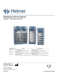
Freezer Service Manual
i.Series™ and Horizon Series™
Model Group
i.Series
Horizon Series
Plasma Storage
iPF120, iPF125 (Version D)
HPF120, HPF125 (Version D)
Laboratory
iLF120, iLF125 (Version D)
HLF120, HLF125 (Version D)
HELMER SCIENTIFIC
14400 Bergen Boulevard
Noblesville, IN 46060 USA
PH +1.317.773.9073
FAX +1.317.773.9082
USA and Canada 800.743.5637
360144-D/B
0086
ISO 13485:2003 CERTIFIED
Document History
Revision
Date
CO
Supersession
Revision Description
A
11 DEC 2012
8187
n/a
Initial release.
B
22 APR 2013
8300
B supersedes A
Revised electrical schematics for Horizon Series freezer.
* Date submitted for Change Order review. Actual release date may vary.
360144-D/B
i
Contents
Section I: General Information. . . . . . . . . . . . . . . . . . . . . . . . . . . . . . . . . . . . . . . . . 6
1 About this Manual . . . . . . . . . . . . . . . . . . . . . . . . . . . . . . . . . . . . . . . . . . . . . . . . . . . . . . . . . . . 6
1.1
1.2
1.3
Intended Audience. . . . . . . . . . . . . . . . . . . . . . . . . . . . . . . . . . . . . . . . . . . . . . . . . . . . . . . . . . . . . . . . . . . . . . 6
Model References. . . . . . . . . . . . . . . . . . . . . . . . . . . . . . . . . . . . . . . . . . . . . . . . . . . . . . . . . . . . . . . . . . . . . . 6
Copyright and Trademark. . . . . . . . . . . . . . . . . . . . . . . . . . . . . . . . . . . . . . . . . . . . . . . . . . . . . . . . . . . . . . . . 6
2Safety . . . . . . . . . . . . . . . . . . . . . . . . . . . . . . . . . . . . . . . . . . . . . . . . . . . . . . . . . . . . . . . . . . . . . 6
2.1Labels. . . . . . . . . . . . . . . . . . . . . . . . . . . . . . . . . . . . . . . . . . . . . . . . . . . . . . . . . . . . . . . . . . . . . . . . . . . . . . . 6
2.2 Avoiding Injury. . . . . . . . . . . . . . . . . . . . . . . . . . . . . . . . . . . . . . . . . . . . . . . . . . . . . . . . . . . . . . . . . . . . . . . . . 6
3 Configuration. . . . . . . . . . . . . . . . . . . . . . . . . . . . . . . . . . . . . . . . . . . . . . . . . . . . . . . . . . . . . . . 7
3.1
3.2
3.3
3.4
Model and Input Power. . . . . . . . . . . . . . . . . . . . . . . . . . . . . . . . . . . . . . . . . . . . . . . . . . . . . . . . . . . . . . . . . . 7
Control System. . . . . . . . . . . . . . . . . . . . . . . . . . . . . . . . . . . . . . . . . . . . . . . . . . . . . . . . . . . . . . . . . . . . . . . . 7
3.2.1i.C³® Control System. . . . . . . . . . . . . . . . . . . . . . . . . . . . . . . . . . . . . . . . . . . . . . . . . . . . . . . . . . . . . . 7
3.2.2 Horizon Series Control System . . . . . . . . . . . . . . . . . . . . . . . . . . . . . . . . . . . . . . . . . . . . . . . . . . . . . 8
Temperature Probes. . . . . . . . . . . . . . . . . . . . . . . . . . . . . . . . . . . . . . . . . . . . . . . . . . . . . . . . . . . . . . . . . . . . 8
3.3.1 Fill Temperature Probe Bottle. . . . . . . . . . . . . . . . . . . . . . . . . . . . . . . . . . . . . . . . . . . . . . . . . . . . . . . 8
3.3.2 Install Additional Probe Through Top Port . . . . . . . . . . . . . . . . . . . . . . . . . . . . . . . . . . . . . . . . . . . . . 8
Chart Recorder. . . . . . . . . . . . . . . . . . . . . . . . . . . . . . . . . . . . . . . . . . . . . . . . . . . . . . . . . . . . . . . . . . . . . . . . 9
3.4.1 Chart Recorder Access . . . . . . . . . . . . . . . . . . . . . . . . . . . . . . . . . . . . . . . . . . . . . . . . . . . . . . . . . . . 9
3.4.2 Install Chart Paper. . . . . . . . . . . . . . . . . . . . . . . . . . . . . . . . . . . . . . . . . . . . . . . . . . . . . . . . . . . . . . . 9
4 References and Compliance. . . . . . . . . . . . . . . . . . . . . . . . . . . . . . . . . . . . . . . . . . . . . . . . . . 10
4.1
4.2
4.3
Alarm Reference. . . . . . . . . . . . . . . . . . . . . . . . . . . . . . . . . . . . . . . . . . . . . . . . . . . . . . . . . . . . . . . . . . . . . . 10
Regulatory Compliance. . . . . . . . . . . . . . . . . . . . . . . . . . . . . . . . . . . . . . . . . . . . . . . . . . . . . . . . . . . . . . . . . 10
WEEE Compliance. . . . . . . . . . . . . . . . . . . . . . . . . . . . . . . . . . . . . . . . . . . . . . . . . . . . . . . . . . . . . . . . . . . . 10
5Warranty. . . . . . . . . . . . . . . . . . . . . . . . . . . . . . . . . . . . . . . . . . . . . . . . . . . . . . . . . . . . . . . . . . 11
5.1
5.2
Rel.i™ Product Warranty USA and Canada. . . . . . . . . . . . . . . . . . . . . . . . . . . . . . . . . . . . . . . . . . . . . . . . . . 11
5.1.1 Rapid Resolution . . . . . . . . . . . . . . . . . . . . . . . . . . . . . . . . . . . . . . . . . . . . . . . . . . . . . . . . . . . . . . . . 11
5.1.2Compressor. . . . . . . . . . . . . . . . . . . . . . . . . . . . . . . . . . . . . . . . . . . . . . . . . . . . . . . . . . . . . . . . . . . . 11
5.1.3Parts. . . . . . . . . . . . . . . . . . . . . . . . . . . . . . . . . . . . . . . . . . . . . . . . . . . . . . . . . . . . . . . . . . . . . . . . . . 11
5.1.4Labor . . . . . . . . . . . . . . . . . . . . . . . . . . . . . . . . . . . . . . . . . . . . . . . . . . . . . . . . . . . . . . . . . . . . . . . . . 11
5.1.5 Additional Warranty Information. . . . . . . . . . . . . . . . . . . . . . . . . . . . . . . . . . . . . . . . . . . . . . . . . . . . . 11
Outside of USA and Canada. . . . . . . . . . . . . . . . . . . . . . . . . . . . . . . . . . . . . . . . . . . . . . . . . . . . . . . . . . . . . 12
Section II: i.Series™ Models. . . . . . . . . . . . . . . . . . . . . . . . . . . . . . . . . . . . . . . . . 13
6 Product Configuration. . . . . . . . . . . . . . . . . . . . . . . . . . . . . . . . . . . . . . . . . . . . . . . . . . . . . . . 13
6.1
6.2
6.3
6.4
6.5
6.6
6.7
Install Battery for Backup Power. . . . . . . . . . . . . . . . . . . . . . . . . . . . . . . . . . . . . . . . . . . . . . . . . . . . . . . . . . 13
Automatic Defrost Cycle. . . . . . . . . . . . . . . . . . . . . . . . . . . . . . . . . . . . . . . . . . . . . . . . . . . . . . . . . . . . . . . . 14
External Monitoring Devices. . . . . . . . . . . . . . . . . . . . . . . . . . . . . . . . . . . . . . . . . . . . . . . . . . . . . . . . . . . . . 14
6.3.1 Connect to Remote Alarm Interface. . . . . . . . . . . . . . . . . . . . . . . . . . . . . . . . . . . . . . . . . . . . . . . . . 14
Move Drawers, Shelves, and Baskets. . . . . . . . . . . . . . . . . . . . . . . . . . . . . . . . . . . . . . . . . . . . . . . . . . . . . . 15
Move Slides and Brackets. . . . . . . . . . . . . . . . . . . . . . . . . . . . . . . . . . . . . . . . . . . . . . . . . . . . . . . . . . . . . . . 16
Level the Freezer . . . . . . . . . . . . . . . . . . . . . . . . . . . . . . . . . . . . . . . . . . . . . . . . . . . . . . . . . . . . . . . . . . . . . 16
Optional Adapter Kits for Medication Dispensing Locks. . . . . . . . . . . . . . . . . . . . . . . . . . . . . . . . . . . . . . . . 16
360144-D/B
ii
7 Settings. . . . . . . . . . . . . . . . . . . . . . . . . . . . . . . . . . . . . . . . . . . . . . . . . . . . . . . . . . . . . . . . . . . 17
7.1
7.2
7.3
7.4
7.5
7.6
7.7
Home Screen . . . . . . . . . . . . . . . . . . . . . . . . . . . . . . . . . . . . . . . . . . . . . . . . . . . . . . . . . . . . . . . . . . . . . . . . 17
7.1.1 Home Screen Functions. . . . . . . . . . . . . . . . . . . . . . . . . . . . . . . . . . . . . . . . . . . . . . . . . . . . . . . . . . 17
Temperature Settings . . . . . . . . . . . . . . . . . . . . . . . . . . . . . . . . . . . . . . . . . . . . . . . . . . . . . . . . . . . . . . . . . . 18
Temperature Calibration . . . . . . . . . . . . . . . . . . . . . . . . . . . . . . . . . . . . . . . . . . . . . . . . . . . . . . . . . . . . . . . . 19
7.3.1 Control Sensor Offset. . . . . . . . . . . . . . . . . . . . . . . . . . . . . . . . . . . . . . . . . . . . . . . . . . . . . . . . . . . . 19
7.3.2 Calibrate Chamber Temperature Probes. . . . . . . . . . . . . . . . . . . . . . . . . . . . . . . . . . . . . . . . . . . . . 21
7.3.3 Calibrate Compressor and Evaporator Probe . . . . . . . . . . . . . . . . . . . . . . . . . . . . . . . . . . . . . . . . . 21
7.3.4 Factory Default Settings. . . . . . . . . . . . . . . . . . . . . . . . . . . . . . . . . . . . . . . . . . . . . . . . . . . . . . . . . . 22
7.3.5 Restore Factory Default Settings. . . . . . . . . . . . . . . . . . . . . . . . . . . . . . . . . . . . . . . . . . . . . . . . . . . 23
7.3.6 Change Factory Settings. . . . . . . . . . . . . . . . . . . . . . . . . . . . . . . . . . . . . . . . . . . . . . . . . . . . . . . . . 23
Test Alarms. . . . . . . . . . . . . . . . . . . . . . . . . . . . . . . . . . . . . . . . . . . . . . . . . . . . . . . . . . . . . . . . . . . . . . . . . . 23
7.4.1 Automatic Chamber Temperature Alarm Test. . . . . . . . . . . . . . . . . . . . . . . . . . . . . . . . . . . . . . . . . . 23
7.4.2 Manual Chamber Alarm Test . . . . . . . . . . . . . . . . . . . . . . . . . . . . . . . . . . . . . . . . . . . . . . . . . . . . . . 24
7.4.3 Power Failure Alarm Test. . . . . . . . . . . . . . . . . . . . . . . . . . . . . . . . . . . . . . . . . . . . . . . . . . . . . . . . . 25
7.4.4 Door Open Alarm Test . . . . . . . . . . . . . . . . . . . . . . . . . . . . . . . . . . . . . . . . . . . . . . . . . . . . . . . . . . . 25
Upgrade System Firmware. . . . . . . . . . . . . . . . . . . . . . . . . . . . . . . . . . . . . . . . . . . . . . . . . . . . . . . . . . . . . . 25
Calibrate the Touchscreen. . . . . . . . . . . . . . . . . . . . . . . . . . . . . . . . . . . . . . . . . . . . . . . . . . . . . . . . . . . . . . . 25
View Manufacturer and Product Information. . . . . . . . . . . . . . . . . . . . . . . . . . . . . . . . . . . . . . . . . . . . . . . . . 26
8Maintenance. . . . . . . . . . . . . . . . . . . . . . . . . . . . . . . . . . . . . . . . . . . . . . . . . . . . . . . . . . . . . . . 26
8.1
8.2
8.3
Recharge Refrigerant . . . . . . . . . . . . . . . . . . . . . . . . . . . . . . . . . . . . . . . . . . . . . . . . . . . . . . . . . . . . . . . . . . 26
Check Monitoring System Battery. . . . . . . . . . . . . . . . . . . . . . . . . . . . . . . . . . . . . . . . . . . . . . . . . . . . . . . . . 26
Clean the Freezer. . . . . . . . . . . . . . . . . . . . . . . . . . . . . . . . . . . . . . . . . . . . . . . . . . . . . . . . . . . . . . . . . . . . . 27
8.3.1 Condenser Grill . . . . . . . . . . . . . . . . . . . . . . . . . . . . . . . . . . . . . . . . . . . . . . . . . . . . . . . . . . . . . . . . 27
8.3.2Exterior. . . . . . . . . . . . . . . . . . . . . . . . . . . . . . . . . . . . . . . . . . . . . . . . . . . . . . . . . . . . . . . . . . . . . . . 27
8.3.3Interior . . . . . . . . . . . . . . . . . . . . . . . . . . . . . . . . . . . . . . . . . . . . . . . . . . . . . . . . . . . . . . . . . . . . . . . 27
8.3.4 Door Gaskets. . . . . . . . . . . . . . . . . . . . . . . . . . . . . . . . . . . . . . . . . . . . . . . . . . . . . . . . . . . . . . . . . . 27
8.3.5 Clean and Refill Probe Bottles. . . . . . . . . . . . . . . . . . . . . . . . . . . . . . . . . . . . . . . . . . . . . . . . . . . . . 27
8.3.6i.C³® Touchscreen. . . . . . . . . . . . . . . . . . . . . . . . . . . . . . . . . . . . . . . . . . . . . . . . . . . . . . . . . . . . . . . 28
8.4 Defrost the Unit Cooler. . . . . . . . . . . . . . . . . . . . . . . . . . . . . . . . . . . . . . . . . . . . . . . . . . . . . . . . . . . . . . . . . 28
8.5 Unit Cooler Removal and Installation . . . . . . . . . . . . . . . . . . . . . . . . . . . . . . . . . . . . . . . . . . . . . . . . . . . . . . 28
8.5.1 Remove the Unit Cooler Cover . . . . . . . . . . . . . . . . . . . . . . . . . . . . . . . . . . . . . . . . . . . . . . . . . . . . 29
8.5.2 Install the Unit Cooler Cover . . . . . . . . . . . . . . . . . . . . . . . . . . . . . . . . . . . . . . . . . . . . . . . . . . . . . . 29
8.6 Access Control Cartridge Removal and Installation . . . . . . . . . . . . . . . . . . . . . . . . . . . . . . . . . . . . . . . . . . . 30
8.6.1 Cartridge Removal. . . . . . . . . . . . . . . . . . . . . . . . . . . . . . . . . . . . . . . . . . . . . . . . . . . . . . . . . . . . . . 30
8.6.2 Cartridge Installation . . . . . . . . . . . . . . . . . . . . . . . . . . . . . . . . . . . . . . . . . . . . . . . . . . . . . . . . . . . . 30
8.7Supplies. . . . . . . . . . . . . . . . . . . . . . . . . . . . . . . . . . . . . . . . . . . . . . . . . . . . . . . . . . . . . . . . . . . . . . . . . . . . . 31
9 Troubleshooting. . . . . . . . . . . . . . . . . . . . . . . . . . . . . . . . . . . . . . . . . . . . . . . . . . . . . . . . . . . . 32
9.1
9.2
9.3
9.4
9.5
General Operation Problems. . . . . . . . . . . . . . . . . . . . . . . . . . . . . . . . . . . . . . . . . . . . . . . . . . . . . . . . . . . . . 32
Chamber Temperature Problems . . . . . . . . . . . . . . . . . . . . . . . . . . . . . . . . . . . . . . . . . . . . . . . . . . . . . . . . . 33
Alarm Activation Problems . . . . . . . . . . . . . . . . . . . . . . . . . . . . . . . . . . . . . . . . . . . . . . . . . . . . . . . . . . . . . . 34
Testing Problems. . . . . . . . . . . . . . . . . . . . . . . . . . . . . . . . . . . . . . . . . . . . . . . . . . . . . . . . . . . . . . . . . . . . . . 38
Condensation and Icing Problems . . . . . . . . . . . . . . . . . . . . . . . . . . . . . . . . . . . . . . . . . . . . . . . . . . . . . . . . 38
10Parts . . . . . . . . . . . . . . . . . . . . . . . . . . . . . . . . . . . . . . . . . . . . . . . . . . . . . . . . . . . . . . . . . . . . . 39
10.1Front . . . . . . . . . . . . . . . . . . . . . . . . . . . . . . . . . . . . . . . . . . . . . . . . . . . . . . . . . . . . . . . . . . . . . . . . . . . . . . . 39
10.1.1 Access Control Option. . . . . . . . . . . . . . . . . . . . . . . . . . . . . . . . . . . . . . . . . . . . . . . . . . . . . . . . . . . 40
10.1.2 Control System and Display. . . . . . . . . . . . . . . . . . . . . . . . . . . . . . . . . . . . . . . . . . . . . . . . . . . . . . . 40
10.2Top. . . . . . . . . . . . . . . . . . . . . . . . . . . . . . . . . . . . . . . . . . . . . . . . . . . . . . . . . . . . . . . . . . . . . . . . . . . . . . . . . 41
10.3Rear. . . . . . . . . . . . . . . . . . . . . . . . . . . . . . . . . . . . . . . . . . . . . . . . . . . . . . . . . . . . . . . . . . . . . . . . . . . . . . . . 42
10.3.1 Electrical Box. . . . . . . . . . . . . . . . . . . . . . . . . . . . . . . . . . . . . . . . . . . . . . . . . . . . . . . . . . . . . . . . . . 43
360144-D/B
iii
10.4Interior. . . . . . . . . . . . . . . . . . . . . . . . . . . . . . . . . . . . . . . . . . . . . . . . . . . . . . . . . . . . . . . . . . . . . . . . . . . . . . 44
10.4.1 Unit Cooler. . . . . . . . . . . . . . . . . . . . . . . . . . . . . . . . . . . . . . . . . . . . . . . . . . . . . . . . . . . . . . . . . . . . 45
10.4.2Storage. . . . . . . . . . . . . . . . . . . . . . . . . . . . . . . . . . . . . . . . . . . . . . . . . . . . . . . . . . . . . . . . . . . . . . . 46
10.4.3 Door and Hinge . . . . . . . . . . . . . . . . . . . . . . . . . . . . . . . . . . . . . . . . . . . . . . . . . . . . . . . . . . . . . . . . 47
11Schematics. . . . . . . . . . . . . . . . . . . . . . . . . . . . . . . . . . . . . . . . . . . . . . . . . . . . . . . . . . . . . . . . 48
11.1 iPF and iLF Models; 120 and 125 Configurations. . . . . . . . . . . . . . . . . . . . . . . . . . . . . . . . . . . . . . . . . . . . . 48
Section III: Horizon Series™ Models. . . . . . . . . . . . . . . . . . . . . . . . . . . . . . . . . . . 50
12 Product Configuration. . . . . . . . . . . . . . . . . . . . . . . . . . . . . . . . . . . . . . . . . . . . . . . . . . . . . . . 50
12.1 Install Battery for Backup Power. . . . . . . . . . . . . . . . . . . . . . . . . . . . . . . . . . . . . . . . . . . . . . . . . . . . . . . . . . 50
12.2 Schedule Defrost Events. . . . . . . . . . . . . . . . . . . . . . . . . . . . . . . . . . . . . . . . . . . . . . . . . . . . . . . . . . . . . . . . 50
12.2.1 Set Current Time . . . . . . . . . . . . . . . . . . . . . . . . . . . . . . . . . . . . . . . . . . . . . . . . . . . . . . . . . . . . . . . 51
12.2.2 Set Defrost Time. . . . . . . . . . . . . . . . . . . . . . . . . . . . . . . . . . . . . . . . . . . . . . . . . . . . . . . . . . . . . . . . 51
12.2.3 Schedule a Defrost Event. . . . . . . . . . . . . . . . . . . . . . . . . . . . . . . . . . . . . . . . . . . . . . . . . . . . . . . . . 51
12.3 External Monitoring Devices. . . . . . . . . . . . . . . . . . . . . . . . . . . . . . . . . . . . . . . . . . . . . . . . . . . . . . . . . . . . . 52
12.3.1 Connect to Remote Alarm Interface. . . . . . . . . . . . . . . . . . . . . . . . . . . . . . . . . . . . . . . . . . . . . . . . . 52
12.4 Move Drawers, Shelves, and Baskets. . . . . . . . . . . . . . . . . . . . . . . . . . . . . . . . . . . . . . . . . . . . . . . . . . . . . . 53
12.5 Move Slides and Brackets. . . . . . . . . . . . . . . . . . . . . . . . . . . . . . . . . . . . . . . . . . . . . . . . . . . . . . . . . . . . . . . 54
12.6 Level the Freezer . . . . . . . . . . . . . . . . . . . . . . . . . . . . . . . . . . . . . . . . . . . . . . . . . . . . . . . . . . . . . . . . . . . . . 54
12.7 Optional Adapter Kits for Medication Dispensing Locks. . . . . . . . . . . . . . . . . . . . . . . . . . . . . . . . . . . . . . . . 54
13 Settings. . . . . . . . . . . . . . . . . . . . . . . . . . . . . . . . . . . . . . . . . . . . . . . . . . . . . . . . . . . . . . . . . . . 55
13.1 Monitor and Controller Interface. . . . . . . . . . . . . . . . . . . . . . . . . . . . . . . . . . . . . . . . . . . . . . . . . . . . . . . . . . 55
13.2 Freezer Setpoint. . . . . . . . . . . . . . . . . . . . . . . . . . . . . . . . . . . . . . . . . . . . . . . . . . . . . . . . . . . . . . . . . . . . . . 56
13.3 Temperature Alarm Setpoints . . . . . . . . . . . . . . . . . . . . . . . . . . . . . . . . . . . . . . . . . . . . . . . . . . . . . . . . . . . . 56
13.3.1 High Temperature Alarm. . . . . . . . . . . . . . . . . . . . . . . . . . . . . . . . . . . . . . . . . . . . . . . . . . . . . . . . . . 57
13.3.2 Low Temperature Alarm. . . . . . . . . . . . . . . . . . . . . . . . . . . . . . . . . . . . . . . . . . . . . . . . . . . . . . . . . . 57
13.4 Temperature Calibration Setpoints . . . . . . . . . . . . . . . . . . . . . . . . . . . . . . . . . . . . . . . . . . . . . . . . . . . . . . . . 57
13.4.1 Monitor Offset. . . . . . . . . . . . . . . . . . . . . . . . . . . . . . . . . . . . . . . . . . . . . . . . . . . . . . . . . . . . . . . . . . 58
13.4.2 Control Sensor Offset. . . . . . . . . . . . . . . . . . . . . . . . . . . . . . . . . . . . . . . . . . . . . . . . . . . . . . . . . . . . 59
13.4.3Hysteresis. . . . . . . . . . . . . . . . . . . . . . . . . . . . . . . . . . . . . . . . . . . . . . . . . . . . . . . . . . . . . . . . . . . . . 60
13.5 Test Alarms. . . . . . . . . . . . . . . . . . . . . . . . . . . . . . . . . . . . . . . . . . . . . . . . . . . . . . . . . . . . . . . . . . . . . . . . . . 60
13.5.1 Chamber Temperature Alarm. . . . . . . . . . . . . . . . . . . . . . . . . . . . . . . . . . . . . . . . . . . . . . . . . . . . . . 60
13.5.2 Power Failure Alarm. . . . . . . . . . . . . . . . . . . . . . . . . . . . . . . . . . . . . . . . . . . . . . . . . . . . . . . . . . . . . 60
13.5.3 Door Open Alarm. . . . . . . . . . . . . . . . . . . . . . . . . . . . . . . . . . . . . . . . . . . . . . . . . . . . . . . . . . . . . . . 61
14Maintenance. . . . . . . . . . . . . . . . . . . . . . . . . . . . . . . . . . . . . . . . . . . . . . . . . . . . . . . . . . . . . . . 61
14.1 Recharge Refrigerant . . . . . . . . . . . . . . . . . . . . . . . . . . . . . . . . . . . . . . . . . . . . . . . . . . . . . . . . . . . . . . . . . . 61
14.2 Check Monitoring System Battery. . . . . . . . . . . . . . . . . . . . . . . . . . . . . . . . . . . . . . . . . . . . . . . . . . . . . . . . . 62
14.3 Clean the Freezer. . . . . . . . . . . . . . . . . . . . . . . . . . . . . . . . . . . . . . . . . . . . . . . . . . . . . . . . . . . . . . . . . . . . . 62
14.3.2Exterior. . . . . . . . . . . . . . . . . . . . . . . . . . . . . . . . . . . . . . . . . . . . . . . . . . . . . . . . . . . . . . . . . . . . . . . 62
14.3.3Interior . . . . . . . . . . . . . . . . . . . . . . . . . . . . . . . . . . . . . . . . . . . . . . . . . . . . . . . . . . . . . . . . . . . . . . . 62
14.3.4 Door Gaskets. . . . . . . . . . . . . . . . . . . . . . . . . . . . . . . . . . . . . . . . . . . . . . . . . . . . . . . . . . . . . . . . . . 62
14.3.5 Clean and Refill Probe Bottle. . . . . . . . . . . . . . . . . . . . . . . . . . . . . . . . . . . . . . . . . . . . . . . . . . . . . . 62
14.4 Unit Cooler Removal and Installation . . . . . . . . . . . . . . . . . . . . . . . . . . . . . . . . . . . . . . . . . . . . . . . . . . . . . . 63
14.4.1 Remove the Unit Cooler Cover . . . . . . . . . . . . . . . . . . . . . . . . . . . . . . . . . . . . . . . . . . . . . . . . . . . . 64
14.4.2 Install the Unit Cooler Cover . . . . . . . . . . . . . . . . . . . . . . . . . . . . . . . . . . . . . . . . . . . . . . . . . . . . . . 64
14.5 Access Control Cartridge Removal and Installation . . . . . . . . . . . . . . . . . . . . . . . . . . . . . . . . . . . . . . . . . . . 65
14.5.1 Cartridge Removal. . . . . . . . . . . . . . . . . . . . . . . . . . . . . . . . . . . . . . . . . . . . . . . . . . . . . . . . . . . . . . 65
14.5.2 Cartridge Installation . . . . . . . . . . . . . . . . . . . . . . . . . . . . . . . . . . . . . . . . . . . . . . . . . . . . . . . . . . . . 66
14.6Supplies. . . . . . . . . . . . . . . . . . . . . . . . . . . . . . . . . . . . . . . . . . . . . . . . . . . . . . . . . . . . . . . . . . . . . . . . . . . . . 66
360144-D/B
iv
15 Troubleshooting. . . . . . . . . . . . . . . . . . . . . . . . . . . . . . . . . . . . . . . . . . . . . . . . . . . . . . . . . . . . 67
15.1
15.2
15.3
15.4
General Operation Problems. . . . . . . . . . . . . . . . . . . . . . . . . . . . . . . . . . . . . . . . . . . . . . . . . . . . . . . . . . . . . 67
Chamber Temperature Problems . . . . . . . . . . . . . . . . . . . . . . . . . . . . . . . . . . . . . . . . . . . . . . . . . . . . . . . . . 67
Alarm Activation Problems . . . . . . . . . . . . . . . . . . . . . . . . . . . . . . . . . . . . . . . . . . . . . . . . . . . . . . . . . . . . . . 70
Condensation and Icing Problems . . . . . . . . . . . . . . . . . . . . . . . . . . . . . . . . . . . . . . . . . . . . . . . . . . . . . . . . 72
16Parts . . . . . . . . . . . . . . . . . . . . . . . . . . . . . . . . . . . . . . . . . . . . . . . . . . . . . . . . . . . . . . . . . . . . . 73
16.1Front . . . . . . . . . . . . . . . . . . . . . . . . . . . . . . . . . . . . . . . . . . . . . . . . . . . . . . . . . . . . . . . . . . . . . . . . . . . . . . . 73
16.1.1 Access Control Option. . . . . . . . . . . . . . . . . . . . . . . . . . . . . . . . . . . . . . . . . . . . . . . . . . . . . . . . . . . 74
16.1.2 Control System Display Parts. . . . . . . . . . . . . . . . . . . . . . . . . . . . . . . . . . . . . . . . . . . . . . . . . . . . . . 74
16.2Top. . . . . . . . . . . . . . . . . . . . . . . . . . . . . . . . . . . . . . . . . . . . . . . . . . . . . . . . . . . . . . . . . . . . . . . . . . . . . . . . . 75
16.3Rear. . . . . . . . . . . . . . . . . . . . . . . . . . . . . . . . . . . . . . . . . . . . . . . . . . . . . . . . . . . . . . . . . . . . . . . . . . . . . . . . 75
16.3.1 Electrical Box. . . . . . . . . . . . . . . . . . . . . . . . . . . . . . . . . . . . . . . . . . . . . . . . . . . . . . . . . . . . . . . . . . 76
16.4Interior. . . . . . . . . . . . . . . . . . . . . . . . . . . . . . . . . . . . . . . . . . . . . . . . . . . . . . . . . . . . . . . . . . . . . . . . . . . . . . 77
16.4.1 Unit Cooler. . . . . . . . . . . . . . . . . . . . . . . . . . . . . . . . . . . . . . . . . . . . . . . . . . . . . . . . . . . . . . . . . . . . 78
16.4.2Storage. . . . . . . . . . . . . . . . . . . . . . . . . . . . . . . . . . . . . . . . . . . . . . . . . . . . . . . . . . . . . . . . . . . . . . . 79
16.4.3 Door and Hinge . . . . . . . . . . . . . . . . . . . . . . . . . . . . . . . . . . . . . . . . . . . . . . . . . . . . . . . . . . . . . . . . 80
17Schematics. . . . . . . . . . . . . . . . . . . . . . . . . . . . . . . . . . . . . . . . . . . . . . . . . . . . . . . . . . . . . . . . 81
17.1 HPF and HLF Models; 120 and 125 Configurations. . . . . . . . . . . . . . . . . . . . . . . . . . . . . . . . . . . . . . . . . . . 81
360144-D/B
v
General Information
Section I: General Information
1
About this Manual
1.1
Intended Audience
This manual is intended for use by end users of the freezer and authorized service technicians.
1.2
Model References
Generic references are used throughout this manual to group models that contain similar features. For
example, “125 models” refers to all models of that size (iPF125, HPF125, iLF125, HLF125). This manual
covers all upright freezers, which may be identified singly, by their size, or by their respective “Series.”
1.3
Copyright and Trademark
Helmer®, i.Series®, i.C³®, Horizon Series™, and Rel.i™ are registered trademarks or trademarks of
Helmer, Inc. in the United States of America. Copyright © 2013 Helmer, Inc. All other trademarks and
registered trademarks are the property of their respective owners.
Helmer, Inc., doing business as (DBA) Helmer Scientific and Helmer.
2Safety
Includes general safety information for freezer operation.
2.1Labels
2.2
Caution: Risk of damage
to equipment or danger to
operator
Caution: Unlock all casters
Caution: Hot surface
Earth / ground terminal
Caution: Shock/electrical
hazard
Protective earth / ground
terminal
Avoiding Injury
► Review safety instructions before installing, using, or maintaining the equipment.
► Do not open multiple, loaded drawers at the same time.
► Do not move a unit whose load exceeds 900 lbs (408 kg).
► Before moving unit, ensure casters are free of debris.
► Never physically restrict any moving component.
► Avoid removing electrical service panels and access panels unless so instructed.
► Use supplied power cords only.
!
360144-D/B
Caution
Decontaminate parts prior to sending for service or repair. Contact Helmer or your
distributor for decontamination instructions and a Return Authorization Number.
6
General Information
3
Configuration
3.1
Model and Input Power
Note
Service information varies depending on the model and power requirements.
This information appears on the product specification label, located on the rear of the freezer below the
electrical box. The model also appears on a label located in the chamber on the upper side of the right
wall.
REF
SN
IPF125
2000000
Version D
www.helmerinc.com
A
REF
IPF125
B
C
SN
2000000
i.Series®
Version D
Pharmacy Freezer
Weight 551 lb
/ 250 kg
C
2012
14400 Bergen Boulevard
Noblesville, IN USA
www.helmerinc.com
Voltage
HZ
Amps
Power
230 V
60
4.3 A
0.99 kW
D
US
Certified
UL 61010-1/CSA 61010-1
0086
Refrigerant Type: 404A
Made in USA
Left: Chamber label. Right: Product Specification label.
3.2
Label
Description
A
Model (REF)
B
Serial number
C
Version
D
Power requirements
Control System
Note
Service information varies depending on the control system.
Helmer freezers have one of two control systems installed. The type of control system varies by model.
3.2.1i.C³® Control System
i.Series freezers are equipped with the i.C³ monitoring and control system. The i.C³ system combines
temperature control and monitoring into a single interface.
360144-D/B
7
General Information
3.2.2
Horizon Series Control System
Horizon Series freezers feature the Horizon combined monitor and temperature controller. The Horizon
Series system controls chamber temperature and monitors and displays operational information.
3.3
Temperature Probes
Number and location of probes varies by model. External probes may be introduced through existing top
ports and immersed in existing probe bottles.
For each probe bottle, use:
► Approximately 4 oz (120 ml) of product simulation solution (1:1 ratio of water to propylene glycol).
Left: Probe bottle with temperature and chart recorder probes. Right: Top access port.
3.3.1
Fill Temperature Probe Bottle
Note
1
2
3
4
3.3.2
360144-D/B
Temperature probes are fragile; handle with care.
Remove all probes from bottle and remove bottle from bracket.
Remove cap and fill with approximately 4 oz (120 ml) of product simulation solution.
Install cap and place bottle in bracket.
Replace probes, immersing at least 2” (50 mm) in solution.
Install Additional Probe Through Top Port
1 Peel back putty to expose port.
2 Insert probe through port into chamber.
3 Insert probe into bottle.
4 Replace putty, ensuring a tight seal.
8
General Information
3.4
Chart Recorder
If installed, refer to the Temperature Chart Recorder Operation and Service Manual on CD.
The chart recorder has a battery system, enabling a period of continuous operation if power is lost.
Battery life varies by manufacturer as well as voltage level remaining. Providing full power is available,
backup power for the temperature chart recorder is available for up to 14 hours.
Prior to use:
► Install battery.
► Add paper.
► Calibrate chart recorder to match upper chamber temperature.
3.4.1
Chart Recorder Access
Open door by either pressing and releasing, or by pulling door open.
3.4.2
Install Chart Paper
1 Press and hold C button. When stylus begins to move left, release button. The LED flashes to
indicate current temperature range.
2 When stylus stops moving, remove chart knob then move knob up and away.
3 Place chart paper on chart recorder.
4 Gently lift stylus and rotate paper so current time line corresponds to time line groove.
5 Hold chart paper and reinstall chart knob.
Note
► For accurate temperature reading, ensure that current time is aligned with
time line groove when chart knob is tightened.
► Do not overtighten knob.
6 Confirm temperature range is set to the correct value.
7 Press and hold C button. When stylus begins to move right, release button.
8 Confirm stylus is marking temperature correctly.
360144-D/B
9
General Information
4
References and Compliance
4.1
Alarm Reference
If an alarm condition is met, an alarm activates. Some alarms are visual only; others are visual and
audible. Some alarms are sent through the remote alarm interface.
The table indicates if an alarm is audible (A), visual (V), or sent through the remote alarm interface (R).
Alarm
4.2
Alarm Type
High Temperature
A, V, R
Low Temperature
A, V, R
Compressor Temperature
A, V, R (i.Series)
Door Open (Time)
A, V, R
Power Failure
A, V, R
Low Battery
V (i.Series)
No Battery
A, V, R (i.Series)
Probe Failure
A, V, R
Communication Failure
A, V, R (i.Series)
Regulatory Compliance
This device complies with the requirements of directive 93/42/EEC concerning Medical Devices, as amended by 2007/47/EC.
Sound level is less than 70 dB(A).
EC
REP
4.3
0086
Emergo Europe
Molenstraat 15
2513 BH
The Hague, Netherlands
WEEE Compliance
The WEEE (waste electrical and electronic equipment) symbol (right) indicates
compliance with European Union Directive WEEE 2002/96/EC and
applicable provisions. The directive sets requirements for labeling and
disposal of certain products in affected countries.
When disposing of this product in countries affected by this directive:
► Do not dispose of this product as unsorted municipal waste.
► Collect this product separately.
► Use collection and return systems available locally.
For more information on the return, recovery, or recycling of this product, contact your local distributor.
360144-D/B
10
General Information
5Warranty
5.1
Rel.i™ Product Warranty USA and Canada
For technical service needs, please contact Helmer at 800-743-5637 or www.helmerinc.com. Have the
model and serial number available when calling.
5.1.1
Rapid Resolution
When a warranty issue arises it is our desire to respond quickly and appropriately. The service department
at Helmer is there for you. Helmer will oversee the handling of your warranty service from start to finish. Therefore, Helmer must give advance authorization for all service calls and/or parts needs relating to a
warranty issue. Any repeat service calls must also be authorized as well. This allows for proper diagnosis
and action. Helmer will not be responsible for charges incurred for service calls made by third parties prior
to authorization from Helmer. Helmer retains the right to replace any product in lieu of servicing it in the field.
5.1.2Compressor
For the warranty period listed below, Helmer will supply the refrigeration compressor, if it is determined
to be defective, at no charge, including freight. Helmer will not be liable for installation, refrigerant, or
miscellaneous charges required to install the compressor beyond the first year of the warranty period.
► i.Series model compressor warranty period is five (5) years.
► Horizon Series model compressor warranty period is three (3) years.
5.1.3Parts
For a period of two (2) years, Helmer will supply at no charge, including freight, any part that fails
due to defects in material or workmanship under normal use, with the exception of expendable items.
Expendable items such as glass, filters, light bulbs, and door gaskets are excluded from this warranty
coverage. Inspection of defective parts by Helmer will be final in determining warranty status. Warranty
procedures must be followed in all events.
5.1.4Labor
For a period of one (1) year, Helmer will cover repair labor costs (including travel) and the cost of
refrigerant and supplies necessary to perform authorized repairs. Repair service must be performed by
an authorized Helmer service agency following the authorization process detailed above. Alternatively,
your facility’s staff may work with a Helmer technician to make repairs. Labor costs for repairs made by
unauthorized service personnel, or without the assistance of a Helmer technician, will be the responsibility
of the end user.
5.1.5
Additional Warranty Information
The time periods set forth above begin two (2) weeks after the original date of shipment from Helmer.
Warranty procedures set forth above must be followed in all events.
There are no warranties which extend beyond the description ON the face
hereof. This warranty is exclusive and in lieu of all other warranties, express
or implied, including without limitation any warranty of merchantability or
fitness for a particular purpose. No warranties of merchantability or fitness
for particular purpose shall apply.
The liability, if any, of Helmer for direct damages whether arising from a
breach of any sales agreement, breach of warranty, negligence, or indemnity,
strict liability or other tort, or otherwise with respect to the goods or any
360144-D/B
11
General Information
services is limited to an amount not to exceed the price of the particular goods
or services giving rise to the liability. In no event shall Helmer be liable for
any indirect, incidental, consequential, or special damages, including without
limitation damages related to lost revenues or profits, or loss of products.
This warranty does not cover damages caused in transit, during installation by accident, misuse, fire, flood, or
acts of God. Further, this warranty will not be valid if Helmer determines that the failure was caused by a lack
of performing recommended equipment maintenance (per Helmer manual) or by using the product in a manner
other than for its intended use. Installation and calibration are not covered under this warranty agreement.
5.2
Outside of USA and Canada
Consult your local distributor for warranty information.
360144-D/B
12
i.Series™ Models
Section II: i.Series™ Models
6
Product Configuration
6.1
Install Battery for Backup Power
The monitoring system and chart recorder each have a battery system, enabling a period of continuous
operation if power is lost.
Note
The monitoring system will start on battery power alone. If the freezer was
previously not connected to AC power and the battery is switched on, the
monitoring system will begin running on battery power.
Battery life varies by manufacturer as well as voltage level remaining. Providing full power is available
and no battery-related alarms are active, backup power for the monitoring system is available for up to 20
hours (the Low Battery alarm will activate after approximately 18 hours of battery use).
!
Caution
► Before installing or replacing batteries, switch the power and battery OFF.
Disconnect the freezer from AC power.
► When installing a replacement battery, use only a battery which meets the
specifications outlined in chapter 8.7 (Supplies).
Note
If AC power is lost, the monitoring system will automatically disable some
features to prolong battery power. Data collection will continue until battery
power is depleted.
The battery is located on the top of the freezer.
Models
iPF and iLF
Battery
(1) rechargeable 12 V lead acid sealed battery
Battery is switched off for shipping. Switch battery on to provide monitoring system with backup power in
the event of AC power failure.
360144-D/B
13
i.Series™ Models
6.2
Automatic Defrost Cycle
The number of programmed defrost events is dependent on environmental conditions and the frequency
of usage. The recommended number of daily defrost cycles is 3 to 4, at even intervals. Defrost events
should take place when the freezer door is opened infrequently.
Note
Depending on the high temperature alarm setpoint and the actual temperature
increase during the defrost cycle, frequent door openings may trigger repeated
high temperature alarms.
The i.C³ monitoring and control system can perform a maximum of four defrost cycles per day. For
information in setting the system time and the time at which each defrost cycle occurs, refer to the i.C³
User Guide.
Defrost Event
Note
6.3
On/Off
Default Time
1
On
12:00 AM
2
On
8:00 AM
3
On
4:00 PM
4
Off
6:00 PM
There must be a minimum of 4 hours between defrost cycles.
External Monitoring Devices
The remote alarm interface is a relay switch with 3 terminals:
► Common (COM)
► Normally Open (NO)
► Normally Closed (NC)
Terminals are dry contacts and do not supply voltage. Interface circuit is either normally open or normally
closed, depending on terminals used.
Requirements for your alarm system determine which alarm wires must connect to terminals.
Note
Do not connect any monitoring device that exceeds the maximum load capacity.
The terminals on the remote alarm interface have the following maximum load capacity:
► 0.5 A at 125 V (AC): 1 A at 250 V (DC)
6.3.1
360144-D/B
Connect to Remote Alarm Interface
1 Switch AC ON/OFF switch OFF. Switch battery switch OFF.
2 On the electrical box, locate the remote alarm terminals.
3 Connect remote alarm wires to appropriate terminals, according to requirements for your alarm
system.
4 Use a cable tie to relieve strain on alarm wires (as necessary).
5 Switch AC ON/OFF switch ON. Switch battery switch ON.
6 Touch Mute to disable the high temperature alarm while freezer reaches operating temperature.
14
i.Series™ Models
6.4
Move Drawers, Shelves, and Baskets
Storage features.
!
Caution
► Before moving drawers, ensure they are completely empty for safe lifting.
► Maximum basket, drawer, or shelf load is 100 lbs (46 kg).
Note
Before moving storage components, protect stored items in freezer from
extended exposure to adverse temperature.
Remove a Drawer or Basket
1 Pull drawer or basket out until it stops.
2 Tilt the front of the drawer or basket upward.
3 Pull drawer or basket free of the slides.
Install a Drawer or Basket
1 Align end guides on drawer or basket with the slides.
2 Gently push drawer or basket into chamber until it stops.
3 Pull drawer or basket out until it stops; check for smooth operation.
Remove a Shelf
1 With one hand, lift front edge of the shelf from the front brackets.
2 With the other hand, reach under the shelf and bump rear edge of the shelf upward to disengage rear
brackets.
Install a Shelf
1 Insert shelf into chamber, placing it on brackets.
2 Gently bump rear edge of the shelf downward to engage brackets.
3 Pulling shelf forward gently; shelf should not disengage from rear brackets.
360144-D/B
15
i.Series™ Models
6.5
Move Slides and Brackets
Remove Drawer Slides
1 Using a screwdriver, remove front bracket retainers.
2 Tap front brackets upward to disengage standards.
3 Remove slides from standards.
Install Drawer Slides
1 Insert slides into standard at appropriate height.
2 Tap front brackets downward to engage standards.
3 Using a screwdriver, install front bracket retainers.
Remove Shelf Brackets
1 Using a screwdriver, remove front bracket retainers.
2 Tap front brackets upward to disengage standards.
3 Remove front brackets from standards.
Install Shelf Brackets
1 Insert front brackets into standard at appropriate height.
2 Tap front brackets downward to engage standards.
3 Using a screwdriver, install front bracket retainers.
6.6
Level the Freezer
Note
► Leveling feet are optional.
► Helmer recommends the use of leveling feet.
► A bubble level may be used to ensure the freezer is level.
Leveling feet must be adjusted to provide unit cooler drainage.
Front-to-Back
1 Using a wrench, raise or lower leveling feet.
2 When freezer is properly leveled, bottom of the unit cooler will slope downward from front to back
(toward the condensate drain line).
Side-to-Side
1 Using a wrench, raise or lower leveling feet.
2 When freezer is properly leveled, bottom of the unit cooler will be horizontal (parallel to the floor).
6.7
Optional Adapter Kits for Medication Dispensing Locks
Contact Helmer Technical Service or your distributor for service documentation pertaining to medication
dispensing locks.
360144-D/B
16
i.Series™ Models
7
Settings
Through the i.C³ monitoring and control system, current settings may be viewed and changed. To view
settings, touch Home, i.C³ APPS, Settings. Use a touch-drag motion to scroll up or down to display
additional settings.
Note
► If the Settings screen is password protected or if viewing settings for the first
time, enter factory default password of “1234”.
► When there is no interaction for two minutes, the Temperature Setpoint
screen closes and returns to the Home screen.
► Default values for general settings, alarm settings, and display settings are
available in the i.C³ User Guide.
► Changing temperature settings affects operation of the freezer. Do not
change settings unless instructed in product documentation or by Helmer
Technical Service.
The i.C³ temperature monitor and controller is programmed at the factory. To change a setting, first enter
the Settings mode, then the setting. The method for accessing the Settings mode for each setting varies.
7.1
Home Screen
The Home screen appears when:
► The Home button is touched from any other screen
► There is no interaction for two minutes on any screen other than those used to enter a password
7.1.1
Home Screen Functions
Note
►
►
►
►
►
►
►
►
360144-D/B
Refer to the i.C³ User Guide for options available on all i.C³ screens.
View current temperature readings
View the current system time and date
Access any of the five customizable applications (touch i.C³ APPS for additional applications)
View detailed information about current or previous alarm events or door open data
View whether the monitoring system is running on battery power
Mute audible alarms
Turn the chamber light on and off
View a graph of the chamber temperature
17
i.Series™ Models
7.2
Temperature Settings
Temperature setpoint values are programmed at the factory. Setpoints can be viewed and changed
through the i.C³ monitoring and control system. To view temperature setpoints, touch Home, i.C³ APPS,
Settings. Details for each setpoint are displayed.
Temperature Controller Programs screen.
Note
Default chamber temperature setpoint is -30.0 ºC.
Change the setpoint if:
► Your organization requires a chamber temperature other than -30.0 ºC.
► The normal chamber temperature is too high or low (after completing preventive maintenance and
applicable troubleshooting tasks).
Confirm:
► Freezer has been placed per location requirements in the operation manual.
► Preventive maintenance has been completed per operation manual.
► Troubleshooting items associated with chamber temperature have been reviewed (if necessary).
Note
If the Settings screen is password protected or if viewing settings for the first
time, enter factory default password of “1234”.
Perform the following:
1 Touch i.C³ APPS, i.C³ Settings.
2 Enter the Settings password.
3 Touch Temperature Setpoints.
4 Touch + or – on the Temperature Setpoint spin box.
► The setpoint is the temperature at which the freezer operates.
Example
► Current setpoint is -30.0 ºC
► Target temperature is -25.0 ºC
► Setpoint adjustment value is +5.0 ºC
5 Touch + or – on the Hysteresis Setpoint spin box.
► The hysteresis setpoint is the allowable fluctuation in temperature, relative to the temperature setpoint.
► A lower hysteresis setpoint will limit the temperature variation to a smaller range.
► A higher setpoint will allow the temperature to vary across a larger range.
Note
360144-D/B
Hysteresis is factory-preset and should not be changed unless directed by
Helmer Technical Service.
18
i.Series™ Models
6 Touch + or – on the Delay on Start-Up spin box.
► Compressor startup is delayed to allow the i.C³ monitoring and control system to start first.
7 Touch + or – on the Duty Cycle of Control Relay during Probe Failure spin box.
► The duty cycle is the percentage of time the compressor will run in the event of a temperature
control probe failure.
8 Touch plus + or – on the Defrost Time spin box.
► The defrost time is the maximum allowable duration which the defrost probe will heat the
evaporator. This value is set to prevent the chamber temperature from increasing excessively
due to a long defrost cycle.
Setting
Initial Factory Value
Temperature Setpoint
-30.0 ºC
Hysteresis Setpoint
2.0 ºC
Delay on Start-Up
2 minutes
Duty Cycle of Control Relay during Probe Failure 100%
Defrost Time
7.3
15 minutes
Temperature Calibration
Temperature calibration values are programmed at the factory. Calibration values can be viewed and
changed through the i.C³ monitoring and control system. To view calibration settings, touch Home, i.C³
APPS, Settings. Details for each setting are displayed.
Temperature Calibration screen.
Note
7.3.1
► If the Settings screen is password protected or if viewing settings for the first
time, enter factory default password of “1234”.
► When there is no interaction for two minutes, the Temperature Setpoint
screen closes and returns to the Home screen.
► Control Sensor and Control Sensor Offset, Evaporator Defrost and
Evaporator Defrost Offset, and Compressor Probe Temperature calibration
settings are factory-preset and should not be changed unless directed by
Helmer Technical Service.
Control Sensor Offset
The temperature controller senses unit cooler temperature through a probe in the unit cooler. The unit
cooler temperature typically varies from the chamber temperature, so an offset value is used by the
control system to compensate for the difference.
The temperature controller adjusts chamber temperature around the freezer setpoint by activating the
compressor when the unit cooler probe registers above the setpoint.
360144-D/B
19
i.Series™ Models
Obtain:
► Independent thermometer, calibrated and traceable per national standards.
► Tape, to attach thermometer to temperature probe.
Perform the following:
1 Remove probes from upper probe bottle.
2 Unscrew cap from bottle.
3 Tape independent thermometer to temperature probe and place in bottle. Probe and thermometer
should be immersed at least 2” (50 mm).
4 Close door and allow chamber temperature to stabilize for 10 minutes.
5 Observe independent thermometer temperature for 10 minutes and determine temperature range.
6 From the range, calculate the average temperature.
7 Remove thermometer and probe from bottle and remove tape.
8 Replace bottle cap, ensuring a tight fit.
9 Place probes in bottle, immersing at least 2” (50 mm).
10 Determine the change in value to reach desired setpoint.
Example
► Current setpoint is -30.0 ºC
► Average temperature is -25.0 ºC
► Offset adjustment value is +5.0 ºC
Enter the new offset value:
1 Touch Home, i.C³ APPS, Settings.
2 Enter the Settings password.
3 Touch Temperature Calibration.
4 Touch + or – on the Control Sensor spin box.
► Value is factory-preset to match the temperature measured in the unit cooler (at the control
sensor) by an independent thermometer.
Note
Control Sensor and Control Sensor Offset are factory-preset and should not be
changed unless directed by Helmer Technical Service.
5 Touch + or – on the Control Sensor Offset spin box.
► The offset should be equal to the difference between the freezer setpoint and the average
temperature measured by an independent thermometer (at the upper probe bottle).
► Raise the offset value to lower chamber temperature; lower the offset value to raise chamber
temperature.
Example
► Measured temperature (at the upper probe bottle) is -28.0 ºC
► Current setpoint is -30.0 ºC
► Offset adjustment value is +2.0 ºC
6 Touch Home to return to home screen.
360144-D/B
20
i.Series™ Models
7.3.2
Calibrate Chamber Temperature Probes
Verify temperature probes are reading chamber temperature correctly by comparing chamber probe
readings to temperature read by an independent thermometer. If chamber temperature probes are not
reading correctly, change the value displayed on the monitor.
Note
► If the variance is within acceptable limits for your organization, changing
probe settings is optional.
► Probes in the bottles are connected to the monitoring system and sense
chamber temperature. These probes do not affect freezer setpoint.
► Default setting for chamber temperature probes is -30.0 ºC.
► Value is factory-preset.
► Value can be changed from -50.0 ºC to +50.0 ºC.
Obtain:
► Independent thermometer, calibrated and traceable per national standards.
► Tape, to attach thermometer to temperature probe.
Calibrate probes:
1 Remove probe from the upper probe bottle.
2 Unscrew the cap from the bottle.
3 Tape the thermometer to the temperature probe, and place them in the bottle. The probe and
thermometer should be immersed at least 2” (50 mm).
4 Close the door and allow the chamber temperature to stabilize for 10 minutes.
5 Observe and note the thermometer temperature.
6 Touch, i.C³ APPS, Settings, Temperature Calibration.
7 Touch + or – on the Upper Temperature spin box to increase or decrease the value to match the
measured value. The message “New Setting Saved” appears next to the spin box.
Note
8
9
10
11
7.3.3
After saving the new temperature value, the displayed temperature may not
match the new value. This is normal.
Replace the probe in probe bottle.
Remove thermometer and probe from bottle and remove tape.
Replace bottle cap, ensuring a tight fit.
Place probe in bottle, immersing at least 2” (50 mm).
Calibrate Compressor and Evaporator Probe
The compressor and evaporator temperature probes have been factory-calibrated. Changing the
calibration settings is not typically necessary and should not be performed unless directed by Helmer
Technical Service.
360144-D/B
21
i.Series™ Models
7.3.4
Factory Default Settings
Settings listed below may be simultaneously returned to factory default values.
Note
The factory default settings may not be the same as the settings that were
factory-calibrated before the freezer was shipped.
Setting
Restored Value
Home Screen Application Icons
i.C³ APPS, Temperature Alarm Test,
Temperature Graph, Information Logs,
Download
Display Brightness
High (3 symbols)
Password (for Settings screen)
1234
Sounds
On
Alarm Volume
9
Alarm Tone
On
Temperature Calibration Values
Values previously entered during setup
Unit ID
Serial number entered at factory
Date Format
MM/DD/YYYY
Day
Not affected (maintained in real-time clock)
Month
Year
Time Format
12-hour
Minute
Not affected (maintained in real-time clock)
Hour
AM/PM
360144-D/B
Language
Language previously selected during setup
Temperature Units
ºC
Password Protection (for Settings screen)
On
Temperature Graph Screensaver
On
Access Control (optional) as Home Page
On
High Temperature Alarm Setpoint
-20.0 ºC
High Temperature Alarm Time Delay
0 minutes
Low Temperature Alarm Setpoint
-35.0 ºC
Low Temperature Alarm Time Delay
0 minutes
Power Failure Alarm Time Delay
1 minute
Probe Failure Alarm Time Delay
0 minutes
Door Open (Time) Alarm Time Delay
3 minutes
Compressor Temperature Alarm Setpoint
50.0 ºC
Compressor Temperature Alarm Time Delay
0 minutes
Chamber Setpoint
-30.0 ºC
Chamber Hysteresis
2.0 ºC
Delay on Start-Up
2 minutes
Control Relay Probe Failure Duty Cycle
100%
Defrost Event #1 On/Off
On
Defrost Event #1 Start Time
12:00 AM
22
i.Series™ Models
Setting
Restored Value
Defrost Event #2 On/Off
On
Defrost Event #2 Start Time
8:00 AM
Defrost Event #3 On/Off
On
Defrost Event #3 Start Time
4:00 PM
Defrost Event #4 On/Off
Off
Defrost Event #4 Start Time
6:00 PM
Defrost Time/Defrost Safety Operation Time
15 minutes
7.3.5
Restore Factory Default Settings
1 Touch Home, i.C³ APPS, Settings, Restore Factory Settings.
2 A “Are you sure you want to restore factory settings?” message appears. Do one of the following:
► Touch Yes. The message screen closes and factory settings are restored.
► Touch No. The message screen closes and factory settings are not restored.
7.3.6
Change Factory Settings
Several of the freezer operating parameters are configured at the factory. The settings listed below are
set at the factory, and may be changed at the direction of Helmer Technical Service.
Setting
Description
Temperature Controller Page
Enable or disable the temperature controller screen
Factory settings may be viewed and changed. Contact Helmer Technical Service to verify if changing
factory settings is necessary, and for instructions in accessing Factory Settings screen.
7.4
Test Alarms
Test alarms to ensure they are working correctly. The freezer has alarms for chamber temperature,
compressor temperature, door open (time), power failure, low battery, and power failure.
7.4.1
Automatic Chamber Temperature Alarm Test
Note
► Test can be aborted by touching Cancel Test.
► Test takes less than 5 minutes.
► If the temperature alarm test does not automatically complete within 2
minutes, restart the i.C³ monitoring system.
When performing an automatic temperature alarm test, the Peiltier device heats or cools the temperature
probe until the high or low alarm setpoint is reached. An event is added to the Event Log to indicate a
temperature alarm was activated. The Alarm Test icon is displayed on the Temperature Graph to indicate
the temperature alarm was test-induced.
360144-D/B
23
i.Series™ Models
Test the low alarm:
1 Identify current setting for low alarm setpoint.
2 Touch Home, i.C³ APPS, Temperature Alarm Test.
3 Touch Low Alarm Test.
4 “Peltier Test Probe Cooling” message appears.
5 When displayed temperature reaches the alarm setpoint, temperature reading turns red.
6 When completed, “Test Complete” appears.
7 Touch Home, i.C³ APPS, Information Logs, Event Log. Touch the event to view event details.
8 Observe the temperature at the time of the low temperature alarm event. Compare this to the alarm
setpoint. If values do not match, refer to chapter 9 (Troubleshooting).
Test the high alarm:
1 Identify current setting for high alarm setpoint.
2 Touch Home, i.C³ APPS, Temperature Alarm Test.
3 Touch High Alarm Test.
4 “Peltier Test Probe Warming” message appears.
5 When displayed temperature reaches the alarm setpoint, the temperature reading turns red.
6 When completed, “Test Complete” appears.
7 Touch Home, i.C³ APPS, Information Logs, Event Log. Touch the event to view event details.
8 Observe the temperature at the time of the high temperature alarm event. Compare this to the alarm
setpoint. If values do not match, refer to chapter 9 (Troubleshooting).
Cancel the test:
1 Touch Home, i.C³ APPS, Temperature Alarm Test.
2 Touch Cancel Test.
Note
7.4.2
When cancelling an automatic test, the message indicating the test is in progress
clears immediately. If a setpoint was reached before the test was cancelled, the
alarm activates and clears as described earlier.
Manual Chamber Alarm Test
Note
Before testing alarms, protect items in freezer from extended exposure to
adverse temperature.
Obtain:
► (1) 4 oz (125 ml) glass of product simulation solution (propylene glycol).
Note
Temperature probes are fragile; handle with care.
Test the high alarm:
1 Identify setting for high alarm setpoint.
2 Place the glass of product simulation solution in the freezer.
3 When the product simulation solution has stabilized at the chamber temperature, remove the solution
from the freezer.
4 Remove the chamber temperature probe from the probe bottle and insert into the product simulation
solution.
5 While stirring probe in the product simulation solution, observe the temperature on the i.C³ display at
which the high temperature alarm sounds.
6 Compare the temperature at which the alarm sounds to the high alarm setpoint. If values do not
match, refer to chapter 9 (Troubleshooting).
360144-D/B
24
i.Series™ Models
7 Remove probe from product simulation solution.
8 Place temperature probe in probe bottle, immersing it at least 2” (50 mm).
7.4.3
Power Failure Alarm Test
Note
During a power failure, the power failure alarm sounds and the battery provides
power to the monitoring system.
1 Change Power Failure delay setting to 0 minutes.
a Touch Home, Settings, Alarm Settings.
b Touch + or – on the Power Failure spin box to change the value to 0.
2 Switch AC ON/OFF switch OFF. Power failure alarm will activate immediately.
3 Switch AC ON/OFF switch ON. Power failure alarm will clear and audible alarm will cease.
4 Change Power Failure time delay to the original setting.
7.4.4
Door Open Alarm Test
1 Change Door Open (Time) delay setting to 0 minutes.
a Touch Home, Settings, Alarm Settings.
b Touch + or – on the Door Open (Time) spin box to change the value to 0.
2 Open door. Alarm will activate immediately.
3 Close door. Alarm will clear and audible alarm will cease.
4 Change the Door Open (Time) setting to the original setting.
7.5
Upgrade System Firmware
Helmer may occasionally issue updates for the i.C³ firmware. Follow upgrade instructions included with
the firmware update.
7.6
Calibrate the Touchscreen
The i.C³ touchscreen has been calibrated at the factory to ensure that when the screen is touched,
the desired key touch is selected. If the i.C³ touchscreen or display circuit board is replaced after the
freezer has been shipped from the factory, the touchscreen must be recalibrated. If the screen must be
recalibrated, contact Helmer Technical Service to obtain the calibration file.
Calibrate the screen:
1 Insert the flash memory device with the calibration program into the USB port on the i.C³ bezel. The
flash memory device can be inserted while any screen displayed on the i.C³.
2 Wait 15 to 30 seconds for the calibration file to load.
3 When the calibration screen appears, remove the flash memory device from the USB port.
4 Follow the on-screen instructions, touching the crosshair icons as they appear on the screen.
Note
For accurate calibration results and to avoid damage to the touchscreen, touch
the crosshairs with the eraser end of a pencil.
5 After all crosshairs have been touched, the i.C³ will reboot and display the language screen.
Note
360144-D/B
► For accurate calibration results and to avoid damage to the touchscreen,
touch the crosshairs with the eraser end of a pencil.
► If the screen was unintentionally touched outside of any of the crosshair
icons, the screen may be recalibrated using the process outlined above.
25
i.Series™ Models
7.7
View Manufacturer and Product Information
View version information for contacting Helmer.
1 Touch i.C³ APPS, Contact Helmer.
2 Manufacturer contact information appears.
3 Software version appears.
8Maintenance
Note
8.1
► Refer to the operation manual for the preventive maintenance schedule.
► Before performing maintenance, protect items in freezer from extended
exposure to adverse temperature.
► Allow freezer temperature to stabilize at setpoint after performing serivce or
after extended door opening.
Recharge Refrigerant
!
Caution
► Review all safety instructions prior to recharging refrigerant. Refer to chapter
2 (Safety).
► Maintenance should only be performed by trained refrigeration technicians.
Note
Use only non-CFC R-404A refrigerant.
Full initial refrigerant charge varies by model and power requirements, which can be found on the product
specification label.
Model
120 and 125 models
Power
Requirements
Initial Charge
Any
29.0 oz (822 g)
Obtain:
► Refrigerant
► Calibrated pressure gauge (0 lbs/in² to 220 lbs/in² (0 kPa to 1520 kPa))
Add refrigerant:
1 Attach pressure gauge to the fittings on the refrigeration lines.
2 Monitor the low side (suction) pressure through a full compressor cycle.
3 Measure the pressure at the end of the next cycle, immediately before the compressor stops.
Note
Pressure varies depending on ambient air temperature.
4 Add refrigerant. Check the pressure on the high side and the low side.
► Low side = 2 lbs/in² to 4 lbs/in² (14 kPa to 28 kPa)
► High side = 180 lbs/in² to 220 lbs/in² (1241 kPa to 1520 kPa)
5 Remove pressure gauge.
8.2
Check Monitoring System Battery
On all i.C³ screens, the Battery icon will appear in the header bar when the system is running on battery
power and the screen brightness will automatically be reduced. The monitoring system will automatically
disable some features to extend battery life.
360144-D/B
26
i.Series™ Models
Check the battery:
1 Switch AC ON/OFF switch OFF.
a Screen should continue to display information with reduced brightness.
b Battery icon will appear on the screen.
c If the display is blank, replace battery.
2 Switch AC ON/OFF switch ON.
Note
8.3
Clean the Freezer
8.3.1
Condenser Grill
!
Caution
Use a battery which meets specifications outlined in chapter 8.7 (Supplies).
Disconnect freezer from AC power when cleaning.
In environments where freezer is exposed to excessive lint or dust, condenser grill may require cleaning
more frequently than stated in preventive maintenance schedule.
Clean the condenser grill using a soft brush and a vacuum cleaner.
8.3.2Exterior
Clean glass surfaces with soft cotton cloth and glass cleaner. Clean exterior surfaces with soft cotton
cloth and non-abrasive liquid cleaner.
8.3.3Interior
Clean painted surfaces with mild detergent. Clean stainless steel surfaces with a general-purpose
laboratory cleaner suitable for stainless steel.
8.3.4
Door Gaskets
Clean with soft cloth and mild soap and water solution.
8.3.5
Clean and Refill Probe Bottles
Note
A kit that includes a probe bottle and propylene glycol is available from Helmer.
Obtain:
► Fresh water-bleach solution (not provided)
► 1:9 ratio of bleach to water
► Bleach is 5% solution of commercial sodium hypochlorite (NaOCl)
► Equivalent oxidizing cleaner/disinfectant approved by your organization may be substituted
► 4 oz (120 ml) of product simulation solution per bottle
► Solution is a 1:1 ratio of water to propylene glycol
Clean and refill bottles:
1 Remove probe from bottle.
2 Remove bottle from bracket.
3 Clean bottle with water-bleach solution.
4 Fill bottle with 4 oz (120 ml) of product simulation solution.
5 Cap bottle tightly to minimize evaporation.
6 Place bottle in bracket.
7 Replace probe, immersing at least 2” (50 mm).
360144-D/B
27
i.Series™ Models
8.3.6i.C³® Touchscreen
Clean touchscreen with a soft, dry cotton cloth.
8.4
Defrost the Unit Cooler
Defrost events may be scheduled to occur at specific times. A defrost event can be triggered on demand
without affecting a programmed defrosting schedule.
1 Touch i.C³ APPS, Temperature Setpoints.
2 Touch the Manual Defrost: Start button.
► The Defrost icon will appear for the duration of the defrost cycle.
3 To cancel, touch the Manual Defrost: Stop button.
8.5Unit Cooler Removal and Installation
If unit cooler cover is not removed as detailed in this procedure the drain port may be damaged. Improper
drainage may result in excessive icing and freezer’s inability to maintain temperature.
Required tools:
► 5/16” socket wrench
► Tool to push putty away from the drain tube
C
A
D
B
E
F
G
Drain tube, fan, and heater components.
Label
360144-D/B
Description
A
Unit cooler cover
B
Drain port
C
Drain fan
D
Fan tube
E
Heater wires
F
Heating element
G
Drain tube
28
i.Series™ Models
8.5.1
Remove the Unit Cooler Cover
1 Switch AC ON/OFF switch OFF. Switch battery switch OFF.
2 On the back of the cabinet, peel the putty back to expose the drain tube (G) and drain heater (F).
!
Caution
The condensate evaporator and water evaporation tray are hot.
3 Verify the heating element is cool. Remove the screws and loosen the pipe straps securing the drain
tube to the cabinet.
4 Remove the drain heater from the drain tube.
5 Remove the drain tube (G) by pulling it downward. The drain tube should separate from the fan tube
(D) at the 90º elbow, leaving the fan tube (D) attached to the fan (C).
a Separate the drain hose inside the cabinet from the unit cooler drain port (B).
b Gently twist the drain hose from left to right to separate it from the unit cooler drain port.
c Pivot the drain tube and drain hose upward then remove the assembly from the cabinet.
6 Remove top drawer, basket, or shelf from the chamber.
Note
For iPF models, remove the Cold-Shield panel. Loosen 3 screws securing the
panel to the cabinet then slide the panel to free it from the screws.
7 Remove the unit cooler cover (A).
a Hold unit cooler cover in place to prevent it from dropping.
b Use the socket wrench to remove 4 screws securing the unit cooler cover.
c Carefully lower unit cooler cover to avoid damage to the fan wiring.
8.5.2
Install the Unit Cooler Cover
1 Verify unit cooler wiring is connected and routed correctly.
a Wiring should be routed above copper tube inside the unit cooler.
b Reconnect wires if they have separated.
2 Attach unit cooler cover.
a Lift unit cooler cover into place.
b Front edge of the cover should be behind the unit cooler case.
c Use the socket wrench to install 4 screws to secure the unit cooler cover.
3 Insert the drain tube and drain hose through the hole in the cabinet.
a Push drain tube and drain hose upward at an angle, toward the unit cooler drain port.
b Pivot the drain tube and drain hose downward then push the assembly upward.
c In the chamber, push the drain hose onto the drain hose.
4 Attach the drain tube to the fan tube.
5 Insert the drain line heater in the drain tube.
a Insert the heater at an upward angle.
b The black heating element should no longer be visible.
6 On the back of the cabinet, press putty around the drain tube and drain line heater.
7 Reinstall top drawer, basket, or shelf if previously removed.
Note
For iPF models, reinstall the Cold-Shield panel.
8 Reattach the pipe straps to secure the drain tube to the cabinet.
9 Switch AC ON/OFF switch ON. Switch battery switch ON.
10 Touch Mute to disable the high temperature alarm while freezer reaches operating temperature.
360144-D/B
29
i.Series™ Models
8.6
Access Control Cartridge Removal and Installation
The Access Control lock cartridge is a serviceable assembly installed on the cabinet.
Required tools:
► Wire cutter
► #2 Phillips screwdriver
8.6.1
Cartridge Removal
1 Switch AC ON/OFF switch OFF. Switch battery switch OFF.
2 Open freezer door and prop the door open.
► If door is locked, use the key to override the Access Control lock, then open door.
3 Use a screwdriver to remove 3 screws securing the Access Control cartridge cover.
4 Remove cover.
Remove
5 Cut the zip tie securing the bundled wires to the cartridge. Separate the spade connectors.
6 Use a screwdriver to remove 2 screws securing the cartridge assembly.
Cut zip tie
Remove
7 Remove cartridge assembly.
8.6.2
360144-D/B
Cartridge Installation
1 Insert upper screw through:
► Upper hole in cartridge body
► Metal latch bushing
► Door latch
► Nylon latch bushing
2 Insert lower screw through:
► Lower hole in cartridge body
► Nylon spacer
3 Place the cartridge against the cabinet and align the screws with the holes in the cabinet.
30
i.Series™ Models
4 Hand-thread 2 screws into the holes in the cabinet.
Latch
Nylon latch
bushing
Metal latch
bushing
Nylon spacer
Hand-thread
screws
Note
Ensure wires are not pinched between the cartridge and the cabinet.
5 Using a screwdriver, tighten the screws.
6 Connect the electrical wires from the cabinet to the wires from the cartridge.
7 Bundle the excess wiring and secure it to the back of the cartridge with a zip tie.
Note
Latch must be in the unlocked position (rotated toward the back of freezer) before
installing cartridge cover.
8 Install the Access Control cartridge cover.
a Place the cover over the cartridge and align the screw holes with the holes in the cabinet.
b Hand-thread 3 screws into the holes in the cabinet.
c Using a screwdriver, tighten the screws.
9 Close freezer door.
10 Switch AC ON/OFF switch ON. Switch battery switch ON.
11 Touch Mute to disable the high temperature alarm while freezer reaches operating temperature.
8.7Supplies
Refrigerant: non-CFC, R-404A
Chart paper: 220419 (52 sheets)
Propylene glycol solution: 400922-2
LED lamp: 400954-1, ≈ 1.3 W
(1) 12 V, 7 Ah rechargeable sealed lead acid battery: 120628
(1) 9 V non-rechargeable alkaline (or equivalent): 120218
360144-D/B
31
i.Series™ Models
9
Troubleshooting
!
9.1
Caution
General Operation Problems
Problem
Possible Cause
Action
Debris in the drawer
slides.
► Pull the drawer out and confirm the slides are free
of debris. Clean if necessary.
Drawer slides are not
lubricated.
► Using a multi-purpose grease, lubricate the
bearings in the slides.
Ice buildup in the
drawer slides.
► Pull the drawer out and confirm the slides are free
of ice. De-ice if necessary.
Drawer is misaligned
or not level.
► Confirm both slides for the drawer are mounted at
the same height.
Drawer slide is faulty.
► Confirm the slide is operating correctly. Replace if
necessary.
Debris in the hinges.
► Confirm the hinges are free of debris. Clean the
hinges if necessary.
Door hinges are not
lubricated.
► Using a general-purpose grease, lubricate the
pivots in the hinges.
Hinge cam is faulty.
► Confirm the hinge cam is not damaged. Replace
the cam if necessary.
The monitor display is
hard to read.
Screen brightness is
set too low.
► Change the screen brightness.
The alarm monitor is
not responding.
Digital electronics are
locked because of an
interruption in power.
► Reset the monitoring system.
“Probe Failure” is
displayed on the
monitor.
Defrost probe or
temperature probe
wiring is an open
circuit.
► Check the continuity of the probe wiring and
connections. Secure the connections if necessary.
► Confirm the probe is providing resistance in the
range of 86 Ω to 110 Ω. Replace the probe if
necessary.
A drawer does not
slide easily.
The door does not
open easily.
360144-D/B
Review all safety instructions prior to troubleshooting. Refer to chapter 2 (Safety).
32
i.Series™ Models
9.2
Chamber Temperature Problems
Problem
Possible Cause
Action
The chamber
temperature displayed
is higher or lower
than the actual
temperature.
Chamber temperature
probe(s) is not
calibrated.
► Check the chamber temperature calibration.
Change the calibration if necessary.
Connections for the
chamber temperature
probe are loose.
► Test the chamber probe connections. Secure the
connections if necessary.
Temperature probe
wiring is an open
circuit.
► Check the continuity of the probe wiring. Replace
the probe if necessary.
Probe bottle is empty,
or the amount of
solution is too low.
► Check the level of product simulation solution in
the bottle. Clean and refill the bottle if necessary.
Solution in the probe
bottle is frozen.
► Refill the bottle with new solution.
Digital electronics are
locked because of an
interruption in power.
► Reset the monitoring system.
Monitor is not
calibrated.
► Confirm the temperature probe is reading correctly. Calibrate the chamber probe if necessary.
A component is
► Contact Helmer Technical Service.
faulty or internal
connections are loose.
360144-D/B
The chamber
temperature meets
an alarm condition,
but the appropriate
temperature alarm is
not active.
Temperature alarm
► Check the current setpoints for the temperature
setpoint was changed.
alarms. Change the setpoints if necessary.
The compressor runs
continuously.
Freezer setpoint is set ► Confirm the setpoint is set within the operating
too low.
range and change it if necessary.
Temperature control
probe in the unit
cooler is faulty.
► Replace the probe if necessary.
Temperature monitor/
control board is faulty.
► Confirm the temperature controller or monitor/
control board is operating correctly. Replace it if
necessary.
Compressor starting
relay is faulty.
► Confirm the relay is operating correctly. Replace
the relay if necessary.
Defrost timer is faulty.
► Replace the defrost timer.
33
i.Series™ Models
Problem
Possible Cause
The chamber
temperature does not
stabilize at the freezer
setpoint.
Temperature monitor/
control board is faulty.
Action
► Confirm the temperature controller or monitor/
control board is operating correctly. Replace it if
necessary.
Condensing unit fan is ► Check the condensing unit fan connections.
not running.
Replace the fan motor if necessary.
Unit cooler fan is not
running.
► Check the voltage to the fan when door switch is
activated. Replace the fan motor or door switch if
necessary.
Compressor motor
has seized.
► Replace the compressor.
Temperature control
probe is faulty.
► Replace the probe if necessary.
Refrigerant level is too ► Check the refrigeration lines for leaks and repair
low.
them if necessary. Check the refrigerant level.
Recharge the refrigerant if necessary.
Compressor starting
relay is faulty.
► Confirm the relay is operating correctly. Replace
the relay if necessary.
Condenser grill is
dirty.
► Check the condenser grill. Clean it if necessary.
Circulation in the
chamber is not
adequate.
► Check if there are any items that may obstruct air
flow and remove them if necessary.
Ambient air
► Confirm freezer location meets requirements. Refer
temperature around
to the operation manual.
the freezer is too high.
A component is
► Contact Helmer Technical Service.
faulty or internal
connections are loose.
Evaporator is covered
with ice and is not
exchanging heat.
9.3
► Initiate a freezer defrost cycle.
Alarm Activation Problems
Problem
The freezer is in
an alarm condition,
but alarms are not
audible.
Possible Cause
Action
Alarm system is faulty. ► Confirm the circuit board and line connections are
functioning correctly.
Monitor/control board
is faulty.
► Replace parts with those included in the control
board kit, or replace the monitor/control board.
Speaker is faulty.
► Replace the speaker.
A component is
► Contact Helmer Technical Service.
faulty or internal
connections are loose.
Audible alarms are
muted.
360144-D/B
► Verify that audible alarms are not muted. If time
remaining is greater than 5 minutes, change MUTE
timer value to 5 minutes and wait until timer resets.
34
i.Series™ Models
Problem
Possible Cause
Action
The freezer meets an
alarm condition, but
the appropriate alarm
is not active.
Monitor/control board
is faulty.
► Replace parts with those included in the control
board kit, or replace the monitor/control board.
Alarm setpoint was
changed.
► Check the current setpoints for the alarms.
A component is
► Contact Helmer Technical Service.
faulty or internal
connections are loose.
The High Temperature
alarm activates when
the door is opened,
then clears shortly
after the door is
closed.
Connections for the
chamber temperature
probe are loose.
► Test the chamber temperature probe connections.
Secure the connections if necessary.
Chamber probe is
faulty.
► Test the probe. Replace the probe if necessary.
Unit cooler fan
continues to run while
the door is open.
► Test the door switch and unit cooler fan
connections. Secure the connections if necessary.
Replace the door switch or fan motor if necessary.
Probe bottle is empty.
► Check the level of product simulation solution in
the bottle. Clean and refill bottle if necessary.
High temperature
alarm setpoint is set
too low.
► Check the setpoint. Change the setpoint if
necessary.
A component is
► Contact Helmer Technical Service.
faulty or internal
connections are loose.
The freezer is
Outlet connection is
connected to power,
faulty.
but the AC Power
Power cord is faulty.
Failure alarm is active.
► Verify power at the outlet. Repair the original
outlet or connect to a different outlet if necessary.
► Confirm the power cord is connected securely. Secure the power cord if necessary.
ON/OFF AC power
switch located inside
the front lower panel
is faulty.
► Replace the ON/OFF AC power switch.
ON/OFF AC power
switch is OFF.
► Turn the ON/OFF AC power switch to the ON
position.
A component is
► Contact Helmer Technical Service.
faulty or internal
connections are loose.
A component is
► Contact Helmer Technical Service.
faulty or internal
connections are loose.
Circuit breaker is
tripped.
360144-D/B
► Reset or replace the circuit breaker.
35
i.Series™ Models
Problem
The Door Open
alarm is activating
sporadically.
Possible Cause
Doors are not closing
completely.
Action
► Confirm the hinge cams are not damaged. Replace the cams if necessary.
Doors are closing but
► Confirm the door gasket seals completely. not sealing completely.
Replace the door gasket if necessary.
Connections for the
door switch are faulty.
► Test the switch connections. Secure the
connections if necessary.
Door switch is faulty.
► Replace the door switch.
Temperature monitor/
controller board is
faulty.
► Replace parts with those included in the control
board kit, or replace the monitor/control board.
Door Open Timeout
is set to zero, causing
the alarm to activate
immediately when the
door is opened.
► Check the time delay for the Door Open alarm.
Change the time delay if necessary.
All alarms are
Alarm system is faulty. ► Confirm the circuit board and line connections are
activating sporadically.
functioning correctly.
Monitor/control board
is faulty.
► Replace parts with those included in the control
board kit, or replace the monitor/control board.
A component is
► Contact Helmer Technical Service.
faulty or internal
connections are loose.
Compressor is
overheating due to
lack of airflow.
► Check the condenser grill. Clean if necessary.
► Confirm freezer location meets requirements.
Condenser alarm
setpoint is too low.
► Confirm the alarm setpoint is set at the expected
or correct value.
Refrigerant level is too ► Check refrigeration lines for leaks and repair if
low.
necessary. Check the refrigerant level. Recharge
refrigerant if necessary.
360144-D/B
36
i.Series™ Models
Problem
The condenser alarm
is active.
Possible Cause
Action
Refrigerant level is too ► Check refrigeration lines for leaks and repair if
low.
necessary. Check refrigerant level. Recharge if
low.
Connections for
► Test the probe connections. Secure the
the condenser
connections if necessary.
temperature probe are
loose.
Condenser
temperature probe is
faulty.
► Test the probe. Replace the probe if necessary.
Condenser fins are
dirty.
► Clean as necessary, or order new ones from
Helmer or your distributor.
Compressor is
overheating due to a
lack of air flow.
► Check the condenser grill and clean if necessary.
► Confirm the freezer is correctly located. Refer to
the operation manual.
Condenser probe is
not calibrated.
► Confirm the condenser probe is reading correctly. Calibrate the probe if necessary.
Condenser alarm
setpoint is too low.
► Confirm the alarm setpoint is at the appropriate
value.
Condenser fan motor
is faulty.
► Replace the condenser fan motor.
A component is
► Contact Helmer Technical Service.
faulty or internal
connections are loose.
An alarm activated,
but the temperature
recorded at activation
does not match the
alarm setpoint.
Monitor settings are
not calibrated.
► Confirm the temperature probe is reading correctly. Calibrate the probe if necessary.
Temperature changed
slightly around the
time of activation.
► No action necessary.
The No Battery
alarm is activating
sporadically.
Battery voltage level
on the backup battery
for the monitoring
system is low.
► Replace the backup battery for the monitoring
system.
The High Temperature Upper chamber
alarm is activating
temperature probe is
sporadically.
not immersed in the
product simulation
solution.
► Confirm the probe bottle is full of solution, and the
probe is placed in the bottle correctly.
A component is
► Contact Helmer Technical Service.
faulty or internal
connections are loose.
Upper chamber
temperature probe is
not calibrated.
360144-D/B
► Confirm the upper temperature probe is reading
correctly. Calibrate the probe if necessary.
37
i.Series™ Models
9.4
Testing Problems
Problem
The automatic
temperature tests do
not work.
Possible Cause
Action
Connections for the
chamber temperature
probe are loose.
► Test the chamber temperature probe connections.
Secure the connections if necessary.
Chamber temperature
probe is faulty.
► Test the chamber temperature probe. Replace the
probe if necessary.
Monitor/control board
is faulty.
► Replace parts with those included in the control
board kit, or replace the monitor/control board.
High Alarm setpoint
► Confirm the alarm setpoints are set at the
is set significantly
expected or correct values.
higher than the default ► Test the temperature alarms manually.
value, or the Low
Alarm setpoint is set
significantly lower
than the default value.
A component is
► Contact Helmer Technical Service.
faulty or internal
connections are loose.
9.5
Condensation and Icing Problems
Problem
There is excessive
water in the water
evaporation tray
inside the lower
compartment in the
back of the unit.
Possible Cause
Action
Humid air is entering
the chamber
► Confirm the freezer is level, and the door is
aligned, closing tightly, and sealing correctly.
Correct issues as necessary.
Heater in the water
evaporation tray is
faulty.
► Confirm the heater is hot and is drawing the
correct current (approximately 0.21 A to 0.35 A).
Replace the heater if necessary.
There is excessive ice Humid air is entering
in the chamber.
the chamber.
► Confirm the freezer is level, and the door is
aligned, closing tightly, and sealing correctly.
Correct issues as necessary.
Unit cooler drain
line is damaged or
restricted.
► Confirm the unit cooler drain line is free of debris
and is not restricted. Remove debris if necessary.
Drain line is plugged.
► Confirm the drain tube is free of debris. Remove
debris if necessary.
External drain fan is
faulty.
► Confirm the external drain fan is running. Hold a
piece of paper in front of the fan and confirm that
the paper is being drawn toward the freezer.
► Confirm the connections are secure. Tighten
connections if necessary.
► Replace the drain line fan if necessary.
Connection between
► Confirm the connection is secure. Tighten the
the unit cooler and the
connection if necessary.
drain line is loose.
There is excessive
moisture on the door.
360144-D/B
Humid air is entering
the chamber.
► Confirm the freezer is level, and the door is
aligned, closing tightly, and sealing correctly.
Relative humidity
around freezer is too
high.
► Confirm freezer location meets requirements.
38
i.Series™ Models
Problem
Possible Cause
Action
After a defrost cycle,
no water flows into
the water evaporation
tray.
Not enough time has
elapsed since the end
of the defrost cycle.
► Allow approximately 20 minutes after the end
of the defrost cycle to check for water in the
evaporation tray.
Drain line is plugged.
► Confirm the drain tube is free of debris. Remove
debris if necessary.
Drain line heater is
faulty.
► Confirm the drain line heater is warm to the touch. Contact Helmer Technical Service to resolve
issues as necessary.
Defrost heater on the
evaporator in the unit
cooler is not working.
► Check for ice buildup on the evaporator by looking
through the fan grill with a flashlight. If there is
significant ice buildup inside or behind the unit
cooler, initiate a defrost cycle of the freezer.
Defrost heater on the
evaporator in the unit
cooler is faulty.
► Confirm the drain line heater is hot and is drawing
the appropriate current during a defrost event
(approximately 3.3 A to 5.5 A).
► Replace the defrost heater if necessary.
10Parts
Note
► Before replacing parts, protect items in freezer from extended exposure to
adverse temperature.
► Allow freezer temperature to stabilize at setpoint after replacing parts or after
extended door opening.
10.1Front
A
B
C
D
E
F
G
Left: iPF120 freezer. Right: Chart recorder and door.
360144-D/B
39
i.Series™ Models
Label
Part Number
A
Temperature chart recorder (standard on plasma
freezer model, optional on laboratory model)
800084-1
CA
B
i.C³ monitoring and control system
Refer to subsequent
section(s) for part numbers
IQ
C
Bezel with chart recorder door
800069-2
-
Bezel without chart recorder door
400998-2
-
Chart recorder door assembly
800070-1
-
D
10.1.1
Schematic
Label
Description
E
Chart paper (52 sheets)
220419
-
F
Chart recorder backup battery
120218
CC
G
Caster (swivel with brake)
220467
-
Access Control Option
A
B
Optional Access Control door lock.
Label
Description
Part Number
A
Access Control cartridge cover
-
B
Access Control door catch (door side)
Not
Access Control cartridge assembly (includes
shown manual override key)
10.1.2
Schematic
Label
-
-
-
Left-hinged door: 800020-1
Right-hinged door: 800020-2
N
Control System and Display
A
B
C
Left: Front view, LCD touchscreen. Right: Rear view showing display board.
360144-D/B
40
i.Series™ Models
Label
Description
Part Number
Schematic
Label
A
Interface cable
800010-1
IG
B
Power cable
800010-1
IH
C
Display assembly (includes touchscreen,
display board, interface cable, speaker)
800042-1
IQ
Note
► The i.C³ display assembly is sensitive to static electricity and can be
damaged by electrostatic discharge. Use proper ESD precautions when
handling the display assembly.
► Although the touchscreen and display board may be replaced independently
of the i.C³ display assembly, Helmer recommends replacing the complete
assembly.
10.2Top
A
B
C
Top features.
Label
360144-D/B
Schematic
Label
Description
Part Number
A
Condenser fan motor
230 V, 50 Hz: 120515
230 V, 60 Hz: 120493
K
B
Compressor
230 V, 50 Hz: 400672-3
230 V, 60 Hz: 400672-4
J
C
Monitoring system backup battery
120628
IB
Not
Condenser probe
shown
800039-1
IL
Not
Solenoid valve
shown
220547
W
Not
Solenoid coil
shown
800096-1
V
41
i.Series™ Models
10.3Rear
G
H
I
J
A
B
C
D
E
K
F
L
M
Rear features (iPF120 model shown).
!
360144-D/B
Schematic
Label
Label
Description
Part Number
A
Electrical box
Refer to subsequent section(s) for
part numbers.
-
B
Drain line fan
120511
Q
C
Drain line heater
120485
T
D
Drain line
-
-
E
Condensate evaporator assembly
(includes condensate evaporator, tray,
and cover)
400790-2
J
F
Power cable
North American models: 800002-1
European models: 800003-1
A
G
Remote alarm contacts
-
-
H
RJ-45 Ethernet port
800008-1
IF
I
USB port
120633
IE
J
RS-232 serial port (optional)
-
K
Battery backup switch
120202
IC
L
Main power switch
120478
C
M
Circuit breaker, 12 A
120220
B
Caution
-
Do not remove the cover from the condensate evaporator tray.
42
i.Series™ Models
10.3.1
Electrical Box
D
A
B
C
Electrical box features (iPF120 model shown).
!
Caution
Label
Schematic
Label
Description
Part Number
A
Power supply board
800035-1
ID
B
Compressor relay
120426
L
C
Power line filter
120400
D
D
Monitor/control board
800034-1
IA
Note
360144-D/B
Disconnect the freezer from AC power before opening the electrical box.
The i.C³ control board is sensitive to static electricity and can be damaged by
electrostatic discharge. Use proper ESD precautions when handling the board.
43
i.Series™ Models
10.4Interior
E
F
G
H
A
B
C
D
Interior features (iPF125 model shown).
Label
360144-D/B
Schematic
Label
Description
Part Number
A
Chart recorder probe
800024-1
CB
B
Upper chamber probe
800038-1
IK
C
Probe bottle and propylene glycol kit
400922-1
-
D
Lower chamber probe
800037-1
IJ
E
Mullion heater (behind strike plates)
800082-1
U
F
Door switch
120380
M
G
Door
Refer to subsequent section(s)
for part numbers
-
H
Storage parts
Refer to subsequent section(s)
for part numbers
-
Not
Strike plate replacement kit (includes strike
shown plates (2 vertical, 2 horizontal), with pre-applied
foam tape, foil tape, and instructions)
400687-1
-
Not
Unit cooler
shown
Refer to subsequent section(s)
for part numbers
F
44
i.Series™ Models
10.4.1Unit Cooler
A
B
C D
E
G
F
Left: Unit cooler. Center and right: Unit cooler parts.
Label
Description
Part Number
A
Unit cooler assembly
120476
F
B
Unit cooler fan motor
120548
E
C
Temperature control probe
800048-1
IT
D
Defrost heater limit thermostat
800014-1
S
E
Defrost heater
120567
R
F
Expansion valve
Not
Defrost temperature probe
shown
360144-D/B
Schematic
Label
120495
-
-
IL
45
i.Series™ Models
10.4.2
Storage
A
B
Storage features (left: iLF125 model shown; right: iPF125 model shown).
Label
360144-D/B
Description
Part Number
A
Full shelf (includes hardware)
120 model: 400414-1
125 model: 400414-2
B
Drawer assembly (includes drawer, 2
slides, hardware)
120 model: 400584-2
125 model: 400584-1
Drawer slide assembly (right side)
Not
shown
120 model: 400541-3
125 model: 400541-1
Not
Drawer slide assembly (left side)
shown
120 model: 400541-4
125 model: 400541-2
Not
Roll-out basket assembly (optional,
shown includes basket, 2 slides, hardware)
120 model: 400890-1
125 model: 400890-2
Not
Roll-out basket slide assembly (right side)
shown
120 model: 400541-3
125 model: 400541-1
Not
Roll-out basket slide assembly (left side)
shown
120 model: 400541-4
125 model: 400541-2
Not
Drawer slide wheel
shown
320815-1
Not
Half shelf (includes hardware)
shown
400413-1
46
i.Series™ Models
10.4.3
Door and Hinge
A
B
C
D
E
F
G
H
I
Door and hinge features (iPF125 model shown).
Label
Part Number
A
Door lock (functions as Access Control manual override
lock on models equipped with Access Control option)
220540
-
B
Upper hinge assembly (includes pin and bracket)
Left hinge: 400960-2
Right hinge: 400960-1
-
C
Upper hinge bearing
220541
D
Door gasket
320726-1
-
E
Door bumper
220441
-
F
Lower hinge cam (quantity 2)
320742-1
-
G
Lower hinge bearing
220375
H
Door stop
320763-1
I
Lower hinge bracket
Right hinge: 400377-1
Left hinge: 400377-2
-
Left hinge: 800020-1
Right hinge: 800020-2
N
Not
Access Control lock cartridge assembly (cabinet side,
shown included with Access Control option)
360144-D/B
Schematic
Label
Description
47
i.Series™ Models
11Schematics
11.1
iPF and iLF Models; 120 and 125 Configurations
i.Series Freezer
iPF and iLF
120 and 125 models
MAIN POWER
230V~ / 50 Hz
208/230V~ / 60 Hz
Page 1 of 2
(A)
POWER CORD
From
i.C3, J18, Pin 2
(F) UNIT COOLER
X
3
(B)
CIRCUIT
BREAKERS
*230V~ ONLY
JUNCTION BOX
(R)
DEFROST
HEATER
(C) MAIN
POWER
SWITCH
SNUBBER
CIRCUIT
4
H
L2 IN
GND
N
4
F
L1 IN
WHITE
(D) RFI Filter
L1 OUT
L2 OUT
YELLOW
(E) UNIT COOLER
FAN
(S) DEFROST HEATER
LIMIT THERMOSTAT
From
i.C3, J18, Pin 5
1
2 Solid State Relay #1
3
L1 TERMINAL STRIP
4 i.C3 Power PCBA
5
i.C3, J18, Pin 9
6
(T) Drain Line Heater
7
8
9
10
(Q) EXTERNAL DRAIN FAN
11
12
(U) Mullion Heater
1
2 COMPRESSOR
L2/NEUTRAL TERMINAL STRIP
3
4 i.C3 Power PCBA
5
6
From
i.C3, J18, Pin 4
7
8
9
10
11
GROUND TERMINAL
1
2 3 4 5 6 7 8
9 10
DC POWER SUPPLY
COMPRESSOR
12
360144-D/B
(J) Condensate
Evaporator
48
i.Series™ Models
i.Series Freezer
iPF and iLF
120 and 125 models
(iQ) Bezel Mount
Components
Reset
Page 2 of 2
Speaker
(iM)
SD Memory Card
i.C3 Display PCBA
USB Host
i.C3 LCD
w/ Touch Screen
LCD Back Light
USB Port
To LCD
LCD Touch Screen
(iG)
USB Data Cable
(iH)
Power Cable
(iF)
Ethernet Port
5
N/L2
L1
Battery
RS232
*Option
BYPASS
ON
F4
(iE)
USB Port
(iD)
i.C3 Power PCBA
USB Port 3
USB Port 4
L1-4
L2-4
(iA)
i.C3 Control PCBA
COM
N.O.
(iT)
Chamber Temp Probe
-
12V
(iB) MONITOR
BATTERY
BACKUP
(CC)
CHART
RECORDER
BATTERY 9V
BACKUP
(iL)
N.O.
Evap Defrost
Control Probe
(iJ)
COM
(CA)
CHART
RECORDER
*Option
-+
+
(iK)
Water Bottle Probe
(iC)
Battery Switch
(CB)
CHART
RECORDER
PROBE
Lower Chamber Probe
(M) DOOR SWITCH
(iL)
(N) Door Lock
Solenoid
*Option
Condensor
Discharge Probe
- +
COM
NC
NO
360144-D/B
L2-2
(J) COMPRESSOR
4-
3+
(V) SOLENOID COIL
1
3-28VDC
2
To Evaporator Defrost Heater
To Unit Cooler Fan
L1-5
To Condensate Evaporator
EXTERIOR
ALARM
CONTACTS
(L)
COMPRESSOR
SSR
(K) CONDENSING UNIT
FAN MOTOR
(W) SOLENOID VALVE
3
L1-2
49
Horizon Series™ Models
Section III: Horizon Series™ Models
12
Product Configuration
12.1
Install Battery for Backup Power
The monitoring system has a battery system, enabling a period of continuous operation if power is lost.
Note
The monitoring system will start on battery power alone. If the freezer was
previously not connected to AC power and the battery is connected, the
monitoring system will begin running on battery power.
Battery life varies by manufacturer as well as voltage level remaining. Providing full power is available, and
no battery-related alarms are active, backup power for the monitoring system is available for up to 2 hours.
!
Caution
► Before installing or replacing batteries, switch the power OFF. Disconnect
the freezer from AC power.
► When installing a replacement battery, use only a battery which meets the
specifications outlined in chapter 14.6 (Supplies).
The battery is located on the top of the freezer.
Models
HPF and HLF
Battery
(1) non-rechargeable 9 V lithium (or equivalent) battery
Battery is taped next to the battery holder. Install and connect the battery to provide monitoring system
with backup power in the event of AC power failure.
12.2
Schedule Defrost Events
Defrost events may be scheduled to occur at specific times.
Access to the defrost controller is available from the back of the freezer, in the electrical box.
Specify the number of defrost events to execute per day, as well as the time at which to initiate each
defrost cycle. The cycles are based on the current time settings on the defrost controller.
The defrost controller features two time indicators and a time adjustment ring. The hour and minute
hands show the current time in hours and minutes. The outer ring shows the current time including AM or
PM, to the nearest 15-minute interval.
360144-D/B
50
Horizon Series™ Models
A
B
C
D
E
Defrost controller with current time set to approximately 9:30 PM.
Label
Description
A
PM indicator
B
Current time indicator (includes AM/PM, to the nearest 15-minute interval)
C
Current time indicator (hour and minutes only)
D
AM indicator
E
Time adjustment ring
12.2.1
Set Current Time
1 Switch the AC ON/OFF switch OFF. Turn the Alarm Disable key switch OFF.
2 Remove the electrical box cover on the back of the freezer.
3 Rotate the time adjustment ring clockwise until the current time indicators show the current time.
4 Replace the electrical box cover.
5 Switch the AC ON/OFF switch ON. Turn the Alarm Disable key switch ON.
6 Press the Mute button to disable the high temperature alarm while freezer reaches operating
temperature.
12.2.2
Set Defrost Time
► Default setting of 3 defrost events per day
► Default times are 12:00 AM, 8:00 AM, 4:00 PM
► Defrost events can be added or removed
► Defrost events can be scheduled for any time of day (in 15-minute intervals)
► Defrost cycle lasts 15 to 30 minutes
► Defrost events must be at least 1 hour apart
Note
12.2.3
Three defrost cycles are recommended for consistent freezer operation.
Schedule a Defrost Event
► Switch defrost event switch(es) to the ON position (outside) to initiate a defrost event at that time.
► Switch defrost event switch(es) to the OFF position (inside) to cancel a defrost event at that time.
1 Switch the AC ON/OFF switch OFF. Turn the Alarm Disable key switch OFF.
2 Remove the electrical box cover on the back of the freezer.
360144-D/B
51
Horizon Series™ Models
3 Add a defrost event:
► At the appropriate time mark, position the switch ON (toward the outer ring).
4 Remove a defrost event:
► At the appropriate time mark, position the switch OFF (toward the inside ring).
5 Replace the electrical box cover.
6 Switch the AC ON/OFF switch ON. Turn the Alarm Disable key switch ON.
7 Press the Mute button to disable the high temperature alarm while freezer reaches operating
temperature.
Defrost controller with defrost times set to On position at 12:00 AM, 8:00 AM, and 4:00 PM.
12.3
External Monitoring Devices
The remote alarm interface is a relay switch with 3 terminals:
► Common (COM)
► Normally Open (NO)
► Normally Closed (NC)
Terminals are dry contacts and do not supply voltage. Interface circuit is either normally open or normally
closed, depending on terminals used.
Requirements for your alarm system determine which alarm wires must connect to terminals.
Note
Do not connect any monitoring device that exceeds the maximum load capacity.
The terminals on the remote alarm interface have the following maximum load capacity:
► 0.5 A at 125 V (AC): 1 A at 250 V (DC)
12.3.1
360144-D/B
Connect to Remote Alarm Interface
1 Switch AC ON/OFF switch OFF. Disconnect the battery.
3 On the electrical box, locate the remote alarm terminals.
4 Connect remote alarm wires to appropriate terminals, according to requirements for your alarm system.
5 Use a cable tie to relieve strain on alarm wires (as necessary).
6 Switch AC ON/OFF switch ON. Reconnect the battery.
7 Press the Mute button to disable the high temperature alarm while freezer reaches operating
temperature.
52
Horizon Series™ Models
12.4
Move Drawers, Shelves, and Baskets
Storage features.
!
Caution
► Before moving drawers, ensure they are completely empty for safe lifting.
► Maximum basket, drawer, or shelf load is 100 lbs (46 kg).
Note
Before moving storage components, protect stored items in freezer from
extended exposure to adverse temperature.
Remove a Drawer or Basket
1 Pull drawer or basket out until it stops.
2 Tilt the front of the drawer or basket upward.
3 Pull drawer or basket free of the slides.
Install a Drawer or Basket
1 Align end guides on drawer or basket with the slides.
2 Gently push drawer or basket into chamber until it stops.
3 Pull drawer or basket out until it stops; check for smooth operation.
Remove a Shelf
1 With one hand, lift front edge of the shelf from the front brackets.
2 With the other hand, reach under the shelf and bump rear edge of the shelf upward to disengage rear
brackets.
Install a Shelf
1 Insert shelf into chamber, placing it on brackets.
2 Gently bump rear edge of the shelf downward to engage brackets.
3 Pulling shelf forward gently; shelf should not disengage from rear brackets.
360144-D/B
53
Horizon Series™ Models
12.5
Move Slides and Brackets
Remove Drawer Slides
1 Using a screwdriver, remove front bracket retainers.
2 Tap front brackets upward to disengage standards.
3 Remove slides from standards.
Install Drawer Slides
1 Insert slides into standard at appropriate height.
2 Tap front brackets downward to engage standards.
3 Using a screwdriver, install front bracket retainers.
Remove Shelf Brackets
1 Using a screwdriver, remove front bracket retainers.
2 Tap front brackets upward to disengage standards.
3 Remove front brackets from standards.
Install Shelf Brackets
1 Insert front brackets into standard at appropriate height.
2 Tap front brackets downward to engage standards.
3 Using a screwdriver, install front bracket retainers.
12.6
Level the Freezer
Note
► Leveling feet are optional.
► Helmer recommends the use of leveling feet.
► A bubble level may be used to ensure the freezer is level.
Leveling feet must be adjusted to provide unit cooler drainage.
Front-to-Back
1 Using a wrench, raise or lower leveling feet.
2 When freezer is properly leveled, bottom of the unit cooler will slope downward from front to back
(toward the condensate drain line).
Side-to-Side
1 Using a wrench, raise or lower leveling feet.
2 When freezer is properly leveled, bottom of the unit cooler will be horizontal (parallel to the floor).
12.7
Optional Adapter Kits for Medication Dispensing Locks
Contact Helmer Technical Service or your distributor for service documentation pertaining to medication
dispensing locks.
360144-D/B
54
Horizon Series™ Models
13
Settings
Through the Horizon Series monitoring and control system, current settings may be viewed and changed.
Note
13.1
► Control Sensor Offset and Hysteresis settings are factory-preset and should
not be changed unless directed by Helmer Technical Service.
► Changing temperature settings affects operation of the freezer. Do not
change settings unless instructed in product documentation or by Helmer
Technical Service.
Monitor and Controller Interface
A
I
B
C
D
E
F
J
G
K
H
L
360144-D/B
Label
Description
Function
A
COOL lamp
Indicates the compressor is running.
B
Display
Displays real-time temperature information, setpoints, and alarms.
C
HIGH TEMP lamp
Indicates when the freezer is in a high temperature alarm condition.
Also indicates the high alarm temperature setpoint is being changed.
D
LOW TEMP lamp
Indicates when the freezer is in a low temperature alarm condition.
Also indicates the low alarm temperature setpoint is being changed.
E
DOOR ALARM lamp
Indicates when the door is open.
F
UP ARROW button
Increases a temperature setting.
G
DOWN ARROW
button
Decreases a temperature setting. Also mutes the audible alarm for
five minutes.
H
SEL button
Toggles between alarm monitor and control modes.
I
SET lamp
Indicates when temperature setpoint or alarm setpoint is being changed.
J
SET button
Allows settings to be selected, prior to changing settings.
K
CONTROL lamp
Indicates when the reading from the temperature probe is displayed.
L
MONITOR lamp
Indicates when the display is showing temperature readings from
the monitor probe. Also indicates when alarm setpoints are being
changed.
55
Horizon Series™ Models
Note
13.2
The Alarm Disable key switch disables all audible alarms. This switch does not
affect alarm lamps or signals sent through the remote alarm interface.
Freezer Setpoint
Note
Default setpoint is -30.0 ºC.
Change the setpoint if:
► Your organization requires a chamber temperature other than -30.0 ºC.
► The normal chamber temperature is too high or low (after completing preventive maintenance and
applicable troubleshooting tasks).
Confirm:
► Freezer has been placed per location requirements in the operation manual.
► Preventive maintenance has been completed per operation manual.
► Troubleshooting items associated with chamber temperature have been reviewed (if necessary).
Change setpoint:
1 Determine the new setpoint.
2 Determine the change in value to reach desired setpoint. Adjustment should be the difference
between current setpoint and new setpoint.
Example
► Current setpoint is -30.0 ºC
► Target setpoint is -25.0 ºC
► Setpoint adjustment value is +5.0 ºC.
3 On the monitoring system, press and release SEL to change to Control mode. CONTROL lamp will
illuminate.
4 Press and hold SET to display the reference temperature.
Note
Reference temperature is typically higher than the chamber temperature.
5 Hold SET and press Up Arrow and Down Arrow as necessary to set the adjustment value
determined in step 2.
6 Release all buttons; the setpoint is changed.
7 Press and release SEL to return to Monitor mode. MONITOR lamp will illuminate.
13.3
Temperature Alarm Setpoints
View setpoints:
1 Hold Up Arrow and Down Arrow for 3 seconds. MONITOR lamp will flash to indicate entry into
program mode.
2 Press SEL until desired setting appears.
3 Observe the setting.
4 To view another setting, press SEL again (optional).
5 Hold Up Arrow and Down Arrow for 3 seconds. MONITOR lamp stops flashing to indicate exit from
program mode.
360144-D/B
56
Horizon Series™ Models
13.3.1
Flashing Lamp
Selected Setting
HIGH TEMP and MONITOR
High Temp alarm setpoint
LOW TEMP and MONITOR
Low Temp alarm setpoint
MONITOR only
Monitor Offset
CONTROL only
Control Sensor Offset
CONTROL only
Control Hysteresis
High Temperature Alarm
► Specifies the temperature at which the High Temperature Alarm activates.
► Default setpoint is -20.0 ºC.
► Setpoint can be changed from -40.0 ºC to +40.0 ºC.
Change the setpoint:
1 Hold Up Arrow and Down Arrow for 3 seconds. MONITOR lamp will flash to indicate entry into
program mode.
2 Press SEL until HIGH TEMP and MONITOR lamps flash.
3 Hold SET, then press Up Arrow or Down Arrow to change the setpoint.
4 Release SET button.
5 Hold Up Arrow and Down Arrow for 3 seconds. MONITOR lamp stops flashing to indicate exit from
program mode. New settings are saved.
13.3.2
Low Temperature Alarm
► Specifies the temperature at which the Low Temperature Alarm activates.
► Default setpoint for is -40.0 ºC.
► Setpoint can be changed from -40.0 ºC to +40.0 ºC.
Change the setpoint:
1 Hold Up Arrow and Down Arrow for 3 seconds. MONITOR lamp will flash to indicate entry into
program mode.
2 Press SEL until LOW TEMP and MONITOR lamps flash.
3 Hold SET, then press Up Arrow or Down Arrow to change the setpoint.
4 Release SET button.
5 Hold Up Arrow and Down Arrow for 3 seconds. MONITOR lamp stops flashing to indicate exit from
program mode. New settings are saved.
13.4
Temperature Calibration Setpoints
View setpoints:
1 Hold Up Arrow and Down Arrow for 3 seconds. MONITOR lamp will flash to indicate entry into
program mode.
2 Press SEL until desired setting appears.
3 Observe the setting.
4 To view another setting, press SEL again (optional).
5 Hold Up Arrow and Down Arrow for 3 seconds. MONITOR lamp stops flashing to indicate exit from
program mode.
360144-D/B
57
Horizon Series™ Models
13.4.1
Flashing Lamp
Selected Setting
HIGH TEMP and MONITOR
High Temp alarm setpoint
LOW TEMP and MONITOR
Low Temp alarm setpoint
MONITOR only
Monitor Offset
CONTROL only
Control Sensor Offset
CONTROL only
Control Hysteresis
Monitor Offset
► Adjust if temperature displayed on the monitor does not match measured chamber temperature.
► Value is factory-set to match an independent thermometer.
► Value can be changed from -10.0 ºC to +10.0 ºC.
Note
► If the variance is within acceptable limits, changing the offset value is optional.
► Probes in the bottle are connected to the monitoring system and sense
chamber temperature. These probes do not affect freezer setpoint.
Obtain:
► Independent thermometer, calibrated and traceable per national standards.
► Tape, to attach thermometer to temperature probe.
Measure the chamber temperature:
1 Remove the probe from the probe bottle.
2 Unscrew the cap from the bottle.
3 Tape the thermometer to the temperature probe, and place them in the bottle. The probe and
thermometer should be immersed at least 2” (50 mm).
4 Close the door and allow the chamber temperature to stabilize for 10 minutes.
5 Observe and note the thermometer temperature.
6 Lower the Offset Value to lower displayed monitor temperature; raise the Offset Value to raise
displayed monitor temperature.
Example
7
8
9
10
► Measured temperature (at the upper probe bottle) is -28.0 ºC
► Displayed temperature is is -30.0 ºC
► Offset adjustment value is -2.0 ºC
Remove thermometer and probe from bottle and remove tape.
Replace the probe in probe bottle.
Replace bottle cap, ensuring a tight fit.
Place the probe in bottle, immersing at least 2” (50 mm).
Enter the new offset value:
1 Hold Up Arrow and Down Arrow for 3 seconds. MONITOR lamp will flash to indicate entry into
program mode.
2 Press SEL until only the MONITOR lamp flashes.
3 Hold SET, then press Up Arrow or Down Arrow to change the setpoint.
4 Release SET button.
5 Hold Up Arrow and Down Arrow for 3 seconds. MONITOR lamp stops flashing to indicate exit from
program mode. New settings are saved.
360144-D/B
58
Horizon Series™ Models
13.4.2
Control Sensor Offset
► Controls chamber temperature.
► Factory-preset.
► Varies for each freezer.
Determine control sensor offset:
Note
Control Sensor Offset is factory-preset and should not be changed unless
directed by Helmer Technical Service.
Obtain:
► Independent thermometer, calibrated and traceable per national standards.
► Tape, to attach thermometer to temperature probe.
Measure the chamber temperature:
1 Remove probes from probe bottle.
2 Unscrew cap from bottle.
3 Tape independent thermometer to temperature probe and place in bottle. Probe and thermometer
should be immersed at least 2” (50 mm).
4 Close door and allow chamber temperature to stabilize for 10 minutes.
5 Observe independent thermometer temperature for 10 minutes and determine temperature range.
6 From the range, calculate the average temperature.
7 Remove thermometer and probe from bottle and remove tape.
8 Replace bottle cap, ensuring a tight fit.
9 Place probes in bottle, immersing at least 2” (50 mm).
10 Determine the change in value to reach desired setpoint.
Example
► Current setpoint is -30.0 ºC
► Average temperature is -25.0 ºC
► Offset adjustment value is +5.0 ºC
Enter the new offset value:
1 Hold Up Arrow and Down Arrow for 3 seconds. MONITOR lamp will flash to indicate entry into
program mode.
2 Press SEL until only the CONTROL lamp flashes.
Note
► Ensure Control Sensor Offset is being changed, and not Hysteresis.
► Control Sensor Offset and Hysteresis have the same visual indicator.
3 Hold SET, then press Up Arrow or Down Arrow to change the setpoint.
4 Release SET button.
5 Hold Up Arrow and Down Arrow for 3 seconds. CONTROL lamp stops flashing to indicate exit from
program mode. New settings are saved.
360144-D/B
59
Horizon Series™ Models
13.4.3Hysteresis
► Default setpoint is 2.0 ºC.
► Allowable temperature variance on each side of the freezer setpoint.
Note
13.5
Hysteresis is factory-preset and should not be changed unless directed by
Helmer Technical Service.
Test Alarms
Test alarms to ensure they are working correctly. The freezer has alarms for chamber temperature, power
failure, and door open (time).
Note
13.5.1
Before testing alarms, protect items in freezer from extended exposure to
adverse temperature.
Chamber Temperature Alarm
Obtain:
► (1) 4 oz (125 ml) glass of product simulation solution (propylene glycol).
Note
Temperature probes are fragile; handle with care.
Test the high alarm:
1 Identify setting for high alarm setpoint.
2 Place the glass of product simulation solution in the freezer.
3 When the product simulation solution has stabilized at the chamber temperature, remove the solution
from the freezer.
4 Remove the chamber temperature probe from the probe bottle and insert into the product simulation
solution.
5 While stirring probe in the product simulation solution, observe the temperature on the monitoring
system display at which the high temperature alarm sounds.
6 Compare the temperature at which the alarm sounds to the high alarm setpoint. If values do not
match, refer to chapter 15 (Troubleshooting).
7 Remove probe from product simulation solution.
8 Place temperature probe in probe bottle, immersing it at least 2” (50 mm).
13.5.2
Power Failure Alarm
Note
During a power failure, the battery should continue to provide power to the
monitoring system.
1 Switch AC ON/OFF switch OFF. Audible power failure alarm will activate immediately and “PoFF”
(power off) will appear on the display.
2 Switch AC ON/OFF switch ON. Audible power failure alarm will cease and “PoFF” will clear from the
display.
360144-D/B
60
Horizon Series™ Models
13.5.3
Door Open Alarm
► Factory-set to 3 minutes.
► Value can not be changed.
Test the alarm:
1 Open freezer door and note the time.
2 After 3 minutes, audible alarm will activate and DOOR ALARM lamp will flash.
3 Close freezer door. Audible door open alarm will cease and DOOR ALARM lamp will stop flashing.
14Maintenance
Note
14.1
► Refer to the operation manual for the preventive maintenance schedule.
► Before performing maintenance, protect items in freezer from extended
exposure to adverse temperature.
► Allow freezer temperature to stabilize at setpoint after performing serivce or
after extended door opening.
Recharge Refrigerant
!
Caution
► Review all safety instructions prior to recharging refrigerant. Refer to chapter
2 (Safety).
► Maintenance should only be performed by trained refrigeration technicians.
Note
Use only non-CFC R-404A refrigerant.
Full initial refrigerant charge varies by model and power requirements, which can be found on the product
specification label.
Model
120 and 125 models
Power
Requirements
230 V, 60 Hz
Initial Charge
29.0 oz (822 g)
Obtain:
► Refrigerant
► Calibrated pressure gauge (0 lbs/in² to 220 lbs/in² (0 kPa to 1520 kPa))
Add refrigerant:
1 Attach pressure gauge to the fittings on the refrigeration lines.
2 Monitor the low side (suction) pressure through a full compressor cycle.
3 Measure the pressure at the end of the next cycle, immediately before the compressor stops.
Note
Pressure varies depending on ambient air temperature.
4 Add refrigerant. Check the pressure on the high side and the low side.
► Low side = 2 lbs/in² to 4 lbs/in² (14 kPa to 28 kPa)
► High side = 180 lbs/in² to 220 lbs/in² (1241 kPa to 1520 kPa)
5 Remove pressure gauge.
360144-D/B
61
Horizon Series™ Models
14.2
Check Monitoring System Battery
The monitoring system does not indicate the charge level of the battery. Regularly test the battery.
Replace battery if the test fails or if the battery has been in use for 1 year.
Test the battery:
1 Switch the AC ON/OFF switch OFF.
a Display should continue to display information.
b If the display is blank, replace battery.
2 Switch AC ON/OFF switch ON.
Note
14.3
Clean the Freezer
14.3.1
Condenser Grill
!
Caution
Use a battery which meets specifications outlined in chapter 14.6 (Supplies).
Disconnect freezer from AC power when cleaning.
In environments where freezer is exposed to excessive lint or dust, condenser grill may require cleaning
more frequently than stated in preventive maintenance schedule.
Clean the condenser grill using a soft brush and a vacuum cleaner.
14.3.2Exterior
Clean glass surfaces with soft cotton cloth and glass cleaner. Clean exterior surfaces with soft cotton
cloth and non-abrasive liquid cleaner.
!
Caution
The condensate evaporator and water evaporation tray are hot.
14.3.3Interior
Clean painted surfaces with mild detergent. Clean stainless steel surfaces with a general-purpose
laboratory cleaner suitable for stainless steel.
14.3.4
Door Gaskets
Clean with soft cloth and mild soap and water solution.
14.3.5
Clean and Refill Probe Bottle
Note
A kit that includes a probe bottle and propylene glycol is available from Helmer.
Obtain:
► Fresh water-bleach solution (not provided)
► 1:9 ratio of bleach to water
► Bleach is 5% solution of commercial sodium hypochlorite (NaOCl)
► Equivalent oxidizing cleaner/disinfectant approved by your organization may be substituted
► 4 oz (120 ml) of product simulation solution per bottle
► Solution is a 1:1 ratio of water to propylene glycol
360144-D/B
62
Horizon Series™ Models
Clean and refill bottle:
1 Remove probe from bottle.
2 Remove bottle from bracket.
3 Clean bottle with water-bleach solution.
4 Fill bottle with 4 oz (120 ml) of product simulation solution.
5 Cap bottle tightly to minimize evaporation.
6 Place bottle in bracket.
7 Replace probe, immersing at least 2” (50 mm).
14.4Unit Cooler Removal and Installation
If unit cooler cover is not removed as detailed in this procedure the drain port may be damaged. Improper
drainage may result in excessive icing and freezer’s inability to maintain temperature.
Required tools:
► 5/16” socket wrench
► Tool to push putty away from the drain tube
C
A
D
B
E
F
G
Drain tube, fan, and heater components.
Label
360144-D/B
Description
A
Unit cooler cover
B
Drain port
C
Drain fan
D
Fan tube
E
Heater wires
F
Heating element
G
Drain tube
63
Horizon Series™ Models
14.4.1
Remove the Unit Cooler Cover
1 Switch AC ON/OFF switch OFF. Disconnect the battery.
2 On the back of the cabinet, peel the putty back to expose the drain tube (G) and drain heater (F).
!
Caution
The condensate evaporator and water evaporation tray are hot.
3 Verify the heating element is cool. Remove the screws and loosen the pipe straps securing the drain
tube to the cabinet.
4 Remove the drain heater from the drain tube.
5 Remove the drain tube (G) by pulling it downward. The drain tube should separate from the fan tube
(D) at the 90º elbow, leaving the fan tube (D) attached to the fan (C).
a Separate the drain hose inside the cabinet from the unit cooler drain port (B).
b Gently twist the drain hose from left to right to separate it from the unit cooler drain port.
c Pivot the drain tube and drain hose upward then remove the assembly from the cabinet.
6 Remove top drawer, basket, or shelf from the chamber.
Note
For HPF models, remove the Cold-Shield panel. Loosen 3 screws securing the
panel to the cabinet then slide the panel to free it from the screws.
7 Remove the unit cooler cover (A).
a Hold unit cooler cover in place to prevent it from dropping.
b Use the socket wrench to remove 4 screws securing the unit cooler cover.
c Carefully lower unit cooler cover to avoid damage to the fan wiring.
14.4.2
Install the Unit Cooler Cover
1 Verify unit cooler wiring is connected and routed correctly.
a Wiring should be routed above copper tube inside the unit cooler.
b Reconnect wires if they have separated.
2 Attach unit cooler cover.
a Lift unit cooler cover into place.
b Front edge of the cover should be behind the unit cooler case.
c Use the socket wrench to install 4 screws to secure the unit cooler cover.
3 Insert the drain tube and drain hose through the hole in the cabinet.
a Push drain tube and drain hose upward at an angle, toward the unit cooler drain port.
b Pivot the drain tube and drain hose downward then push the assembly upward.
c In the chamber, push the drain hose onto the drain hose.
4 Attach the drain tube to the fan tube.
5 Insert the drain line heater in the drain tube.
a Insert the heater at an upward angle.
b The black heating element should no longer be visible.
6 On the back of the cabinet, press putty around the drain tube and drain line heater.
7 Reinstall top drawer, basket, or shelf if previously removed.
Note
For HPF models, reinstall the Cold-Shield panel.
8 Reattach the pipe straps to secure the drain tube to the cabinet.
9 Switch AC ON/OFF switch ON. Reconnect the battery.
10 Press the Mute button to disable the high temperature alarm while freezer reaches operating
temperature.
360144-D/B
64
Horizon Series™ Models
14.5
Access Control Cartridge Removal and Installation
The Access Control lock cartridge is a serviceable assembly installed on the freezer cabinet.
Required tools:
► Needle nose pliers
► #10 spanner driver
14.5.1
Cartridge Removal
1 Switch AC ON/OFF switch OFF. Disconnect the battery.
2 Open freezer door and prop the door open.
► If door is locked, use the key to override the Access Control lock, then open door.
3 Use a screwdriver to remove 3 screws securing the Access Control cartridge cover.
4 Remove cover.
Remove
5 Cut the zip tie securing the bundled wires to the cartridge. Separate the spade connectors.
6 Use a screwdriver to remove 2 screws securing the cartridge assembly.
Cut zip tie
Remove
7 Remove cartridge assembly.
360144-D/B
65
Horizon Series™ Models
14.5.2
Cartridge Installation
1 Insert upper screw through:
► Upper hole in cartridge body
► Metal latch bushing
► Door latch
► Nylon latch bushing
2 Insert lower screw through:
► Lower hole in cartridge body
► Nylon spacer
3 Place the cartridge against the cabinet and align the screws with the holes in the cabinet.
4 Hand-thread 2 screws into the holes in the cabinet.
Latch
Nylon latch
bushing
Metal latch
bushing
Nylon spacer
Hand-thread
screws
Note
Ensure wires are not pinched between the cartridge and the cabinet.
5 Using a screwdriver, tighten the screws.
6 Connect the electrical wires from the cabinet to the wires from the cartridge.
7 Bundle the excess wiring and secure it to the back of the cartridge with a zip tie.
Note
Latch must be in the unlocked position (rotated toward the back of freezer) before
installing cartridge cover.
8 Install the Access Control cartridge cover.
a Place the cover over the cartridge and align the screw holes with the holes in the cabinet.
b Hand-thread 3 screws into the holes in the cabinet.
c Using a screwdriver, tighten the screws.
9 Close freezer door.
10 Switch AC ON/OFF switch ON. Reconnect the battery.
11 Press the Mute button to disable the high temperature alarm while freezer reaches operating
temperature.
14.6Supplies
Refrigerant: non-CFC, R-404A
Chart paper: 220419 (52 sheets)
Propylene glycol solution: 400922-2
(1) 9 V non-rechargeable lithium (or equivalent) battery: 120399
(1) 9 V non-rechargeable alkaline (or equivalent) battery: 120218
360144-D/B
66
Horizon Series™ Models
15
Troubleshooting
!
15.1
Caution
General Operation Problems
Problem
A drawer does not
slide easily.
The door does not
open easily.
15.2
Review all safety instructions prior to troubleshooting. Refer to chapter 2 (Safety).
Possible Cause
Action
Debris in the drawer
slides.
► Pull the drawer out and confirm the slides are free
of debris. Clean if necessary.
Drawer slides are not
lubricated.
► Using a multi-purpose grease, lubricate the
bearings in the slides.
Ice buildup in the
drawer slides.
► Pull the drawer out and confirm the slides are free
of ice. De-ice if necessary.
Drawer is misaligned
or not level.
► Confirm both slides for the drawer are mounted at
the same height.
Drawer slide is faulty.
► Confirm the slide is operating correctly. Replace if
necessary.
Debris in the hinges.
► Confirm the hinges are free of debris. Clean the
hinges if necessary.
Door hinges are not
lubricated.
► Using a general-purpose grease, lubricate the
pivots in the hinges.
Hinge cam is faulty.
► Confirm the hinge cam is not damaged. Replace
the cam if necessary.
Chamber Temperature Problems
Problem
The chamber
temperature displayed
is higher or lower
than the actual
temperature.
Possible Cause
Action
Connections for the
chamber temperature
probe are loose.
► Test the chamber probe connections. Secure the
connections if necessary.
Temperature probe
wiring is an open
circuit.
► Check the continuity of the probe wiring. Replace
the probe if necessary.
Probe bottle is empty,
or the amount of
solution is too low.
► Check the level of product simulation solution in
the bottle. Clean and refill the bottle if necessary.
Solution in the probe
bottle is frozen.
► Refill the bottle with new solution.
Digital electronics are
locked because of an
interruption in power.
► Reset the monitoring system.
Monitor is not
calibrated.
► Confirm the temperature probe is reading correctly. Calibrate the chamber probe if necessary.
A component is
► Contact Helmer Technical Service.
faulty or internal
connections are loose.
360144-D/B
67
Horizon Series™ Models
Problem
“Prob” appears on
the display, but the
chamber temperature
is set correctly.
Possible Cause
Action
Connections for the
chamber temperature
probe are loose.
► Test the probe connections. Secure the
connections if necessary.
Temperature probe
wiring is an open
circuit.
► Check the continuity of the probe wiring and
connections. Secure the connections or replace
the probe if necessary.
A component is faulty.
► Contact Helmer Technical Service.
An error code displays A component is
► Contact Helmer Technical Service.
on the monitor.
faulty or internal
connections are loose.
360144-D/B
The chamber
temperature meets
an alarm condition,
but the appropriate
temperature alarm is
not active.
Temperature alarm
► Check the current setpoints for the temperature
setpoint was changed.
alarms. Change the setpoints if necessary.
The compressor runs
continuously.
Freezer setpoint is set ► Confirm the setpoint is set within the operating
too low.
range and change it if necessary.
Temperature control
probe in the unit
cooler is faulty.
► Confirm the unit cooler probe is providing
resistance in the range of 98 Ω to 110 Ω. Replace
the probe if necessary.
Temperature monitor/
control board is faulty.
► Confirm the temperature controller or monitor/
control board is operating correctly. Replace it if
necessary.
Compressor starting
relay is faulty.
► Confirm the relay is operating correctly. Replace
the relay if necessary.
68
Horizon Series™ Models
Problem
The chamber
temperature does not
stabilize at the freezer
setpoint.
Possible Cause
Action
Monitor/control board
is faulty.
► Confirm the temperature controller or monitor/
control board is operating correctly. Replace it if
necessary.
Compressor starting
relay is faulty.
► Confirm the relay is operating correctly. Replace
the relay if necessary.
Temperature monitor/
controller board is
faulty.
► Confirm the temperature monitor/controller board
is operating correctly. Replace the board if
necessary.
Condensing unit fan is ► Check the condensing unit fan connections.
not running.
Replace the fan motor if necessary.
Unit cooler fan is not
running.
► Check the voltage to the fan when door switch is
activated. Replace the fan motor or door switch if
necessary.
Compressor motor
has seized.
► Replace the compressor.
Temperature control
probe is out of
calibration.
► Confirm the probe is providing accurate
temperature readings.
Temperature control
probe is faulty.
► Confirm the probe is providing resistance in the
range of 98 Ω to 110 Ω. Replace the probe if
necessary.
Refrigerant level is too ► Check the refrigeration lines for leaks and repair
low.
them if necessary. Check the refrigerant level.
Recharge the refrigerant if necessary.
Probe bottle is empty.
► Refill the probe bottle.
The condenser grill is
dirty.
► Check the condenser grill. Clean the grill if
necessary.
Air circulation at the
top of the chamber is
not adequate.
► Check if there are any items that may obstruct air
flow and remove them if necessary.
Ambient air
► Confirm the freezer is placed appropriately.
temperature around
the freezer is too high.
A component is
► Contact Helmer Technical Service.
faulty or internal
connections are loose.
360144-D/B
69
Horizon Series™ Models
15.3
Alarm Activation Problems
Problem
The freezer is in an
alarm condition, but
the appropriate alarm
is not audible or
active.
Possible Cause
Action
Alarm system is faulty. ► Confirm the circuit board and line connections are
functioning correctly.
Monitor/control board
is faulty.
► Replace parts with those included in the control
board kit, or replace the monitor/control board.
Alarm buzzer is faulty.
► Replace the alarm buzzer or speaker.
A component is
► Contact Helmer Technical Service.
faulty or internal
connections are loose.
The High Temperature
alarm activates when
the door is opened,
then clears shortly
after the door is
closed.
Alarm Disable key is
in the OFF position.
► Turn the Alarm Disable key to the ON position.
Alarm setpoint was
changed.
► Check the current setpoints for the alarms.
Connections for the
chamber temperature
probe are loose.
► Test the chamber temperature probe connections.
Secure the connections if necessary.
Chamber probe is
faulty.
► Test the probe. Replace the probe if necessary.
Unit cooler fan
continues to run while
the door is open.
► Test the door switch and unit cooler fan
connections. Secure the connections if necessary.
Replace the door switch or fan motor if necessary.
Probe bottle is empty.
► Check the level of product simulation solution in
the bottle. Clean and refill bottle if necessary.
High temperature
alarm setpoint is set
too low.
► Check the setpoint. Change the setpoint if
necessary.
A component is
► Contact Helmer Technical Service.
faulty or internal
connections are loose.
The freezer is
Outlet connection is
connected to power,
faulty.
but the AC Power
Power cord is faulty.
Failure alarm is active.
► Verify power at the outlet. Repair the original
outlet or connect to a different outlet if necessary.
► Confirm the power cord is connected securely. Secure the power cord if necessary.
ON/OFF AC power
switch located inside
the front lower panel
is faulty.
► Replace the ON/OFF AC power switch.
ON/OFF AC power
switch is OFF.
► Turn the ON/OFF AC power switch to the ON
position.
A component is
► Contact Helmer Technical Service.
faulty or internal
connections are loose.
Circuit breaker was
tripped.
360144-D/B
► Confirm the circuit breaker switch is seated. Push the circuit breaker switch to reset the circuit
breaker.
70
Horizon Series™ Models
Problem
The Door Open
alarm is activating
sporadically.
Possible Cause
Action
Door is not closing
completely.
► Confirm the hinge cams are not damaged. Replace the cams if necessary.
Door is closing but not ► Confirm the door gasket seals completely. sealing completely.
Replace the door gasket if necessary.
Connections for the
door switch are faulty.
► Test the switch connections. Secure the
connections if necessary.
Door switch is faulty.
► Replace the door switch.
Monitor/control board
is faulty.
► Replace parts with those included in the control
board kit, or replace the monitor/control board.
A component is
► Contact Helmer Technical Service.
faulty or internal
connections are loose.
All alarms are
Alarm system is faulty. ► Confirm the circuit board and line connections are
activating sporadically.
functioning correctly.
Monitor/control board
is faulty.
► Replace parts with those included in the control
board kit, or replace the monitor/control board.
A component is
► Contact Helmer Technical Service.
faulty or internal
connections are loose.
Compressor is
overheating due to
lack of airflow.
► Check the condenser grill. Clean if necessary.
► Confirm freezer location meets requirements.
Condenser alarm
setpoint is too low.
► Confirm the alarm setpoint is set at the expected
or correct value.
Refrigerant level is too ► Check refrigeration lines for leaks and repair if
low.
necessary. Check the refrigerant level. Recharge
refrigerant if necessary.
An alarm activated,
but the temperature
recorded at activation
does not match the
alarm setpoint.
Condenser probe is
not calibrated.
► Contact Helmer Technical Service to confirm
the condenser probe is reading correctly and to
calibrate the probe if necessary.
Temperature changed
slightly around the
time of activation.
► No action necessary.
The High Temperature Chamber temperature ► Confirm the probe bottle is full of solution, and the
alarm is activating
probe is not immersed
probe is placed in the bottle correctly.
sporadically.
in the product
simulation solution.
A component is
► Contact Helmer Technical Service.
faulty or internal
connections are loose.
Chamber temperature
probe is not
calibrated.
360144-D/B
► Confirm the temperature probe is reading correctly. Calibrate the probe if necessary.
71
Horizon Series™ Models
15.4
Condensation and Icing Problems
Problem
There is excessive
water in the water
evaporation tray
inside the lower
compartment in the
back of the unit.
Possible Cause
Action
Humid air is entering
the chamber
► Confirm the freezer is level, and the door is
aligned, closing tightly, and sealing correctly.
Correct issues as necessary.
Heater in the water
evaporation tray is
faulty.
► Confirm the heater is hot and is drawing the
correct current (approximately 0.21 A to 0.35 A).
Replace the heater if necessary.
There is excessive ice Humid air is entering
in the chamber.
the chamber.
► Confirm the freezer is level, and the door is
aligned, closing tightly, and sealing correctly.
Correct issues as necessary.
Unit cooler drain
line is damaged or
restricted.
► Confirm the unit cooler drain line is free of debris
and is not restricted. Remove debris if necessary.
Drain line is plugged.
► Confirm the drain tube is free of debris. Remove
debris if necessary.
External drain fan is
faulty.
► Confirm the external drain fan is running. Hold a
piece of paper in front of the fan and confirm that
the paper is being drawn toward the freezer.
► Confirm the connections are secure. Tighten
connections if necessary.
► Replace the drain line fan if necessary.
Connection between
► Confirm the connection is secure. Tighten the
the unit cooler and the
connection if necessary.
drain line is loose.
There is excessive
moisture on the door.
After a defrost cycle,
no water flows into
the water evaporation
tray.
360144-D/B
Humid air is entering
the chamber.
► Confirm the freezer is level, and the door is
aligned, closing tightly, and sealing correctly.
Relative humidity
around freezer is too
high.
► Confirm freezer location meets requirements.
Not enough time has
elapsed since the end
of the defrost cycle.
► Allow approximately 20 minutes after the end
of the defrost cycle to check for water in the
evaporation tray.
Drain line is plugged.
► Confirm the drain tube is free of debris. Remove
debris if necessary.
Drain line heater is
faulty.
► Confirm the drain line heater is warm to the touch. Contact Helmer Technical Service to resolve
issues as necessary.
Defrost heater on the
evaporator in the unit
cooler is not working.
► Check for ice buildup on the evaporator by looking
through the fan grill with a flashlight. If there is
significant ice buildup inside or behind the unit
cooler, initiate a defrost cycle of the freezer.
Defrost heater on the
evaporator in the unit
cooler is faulty.
► Confirm the drain line heater is hot and is drawing
the appropriate current during a defrost event
(approximately 3.3 A to 5.5 A).
► Replace the defrost heater if necessary.
72
Horizon Series™ Models
16Parts
Note
► Before replacing parts, protect items in freezer from extended exposure to
adverse temperature.
► Allow freezer temperature to stabilize at setpoint after replacing parts or after
extended door opening.
16.1Front
A
B C
D
E
Front features (HLF125 model shown).
Label
360144-D/B
Schematic
Label
Description
Part Number
A
Temperature chart recorder (standard on
plasma freezer models, optional on laboratory
models)
800083-1
CA
B
Horizon Series monitoring and control system
Refer to subsequent section(s)
for part numbers
HA
C
Bezel (with chart recorder door)
800093-1
-
Bezel (without chart recorder door)
800092-1
-
Not
Chart paper (52 sheets)
shown
220419
-
Not
Chart recorder backup battery
shown
120218
CC
D
Alarm disable key switch
120227
HE
E
Caster (swivel with brake)
220467
-
73
Horizon Series™ Models
16.1.1
Access Control Option
A
C
B
D
Optional Access Control door lock and keypad.
Label
Description
Part Number
A
Access Control cartridge cover
-
B
Access Control door catch (door side)
Not
Access Control cartridge assembly (includes
shown manual override key)
16.1.2
Schematic
Label
-
-
-
Left-hinged door: 800020-1
Right-hinged door: 800020-2
N
-
C
Bezel
With chart recorder: 800074-1
Without chart recorder:
800057-1
D
Access control keypad
800007-1
HM
Control System Display Parts
A
Left: Control board. Right: Display with touchpad.
Label
A
Note
360144-D/B
Description
Part Number
Control board assembly
800006-1
Schematic
Label
HA
The display board is sensitive to static electricity and can be damaged by
electrostatic discharge. Use proper ESD precautions when handling the board.
74
Horizon Series™ Models
16.2Top
A
B
C
Top features.
Label
Schematic
Label
Description
Part Number
A
Condenser fan motor
230 V, 50 Hz: 120515
230 V, 60 Hz: 120493
K
B
Compressor
230 V, 50 Hz: 400672-3
230 V, 60 Hz: 400672-4
J
C
Monitoring system backup battery
120399
HH
Not
Solenoid valve
shown
220547
W
Not
Solenoid coil
shown
800096-1
V
16.3Rear
A
B
C
D
E
G
H
I
F
Rear features (HPF125 model shown).
360144-D/B
75
Horizon Series™ Models
!
16.3.1
Schematic
Label
Label
Description
Part Number
A
Electrical box
Refer to subsequent section(s) for
part numbers.
-
B
Drain line fan
120511
Q
C
Drain line heater
120485
T
D
Drain line
-
-
E
Condensate evaporator assembly (includes
condensate evaporator, tray, and cover)
400790-2
J
F
Power cable
North American models: 800002-1
European models: 800003-1
A
G
Remote alarm contacts
-
-
H
Main power switch
120478
C
I
Circuit breaker, 12 A
120220
B
Caution
Do not remove the cover from the condensate evaporator tray.
Electrical Box
A
B
C
D
E
Electrical box features (HPF111 model shown).
!
360144-D/B
Caution
Disconnect the freezer from AC power before opening the electrical box.
76
Horizon Series™ Models
Label
Description
Part Number
Schematic
Label
A
Alarm buzzer
120227
HD
B
Defrost timer
800015-2
HF
C
Compressor relay
120426
D
Temperature control transformer
800086-1
E
Power line filter
120400
D
120505
HN
Not
12 V DC power supply for Access
shown Control (optional)
Note
L
HO
The control board is sensitive to static electricity and can be damaged by
electrostatic discharge. Use proper ESD precautions when handling the board.
16.4Interior
E F
G
H
A
B
C
D
Interior parts (iLF125 model shown).
Label
A
360144-D/B
Schematic
Label
Description
Part Number
Chart recorder probe
800024-1
CB
B
Chamber probe
800029-1
HC
C
Probe bottle and propylene glycol kit
400922-1
-
D
Mullion heater (behind strike plates)
800082-1
U
E
Unit cooler
Refer to subsequent section(s)
for part numbers
F
F
Door switch
120380
M
G
Door
Refer to subsequent section(s)
for part numbers
-
H
Storage parts
Refer to subsequent section(s)
for part numbers
-
77
Horizon Series™ Models
Label
Description
Schematic
Label
Part Number
Not
Strike plate replacement kit (includes strike
shown plates (2 vertical, 2 horizontal), with preapplied foam tape, foil tape, and instructions)
400687-1
-
Not
Unit cooler
shown
-
F
16.4.1Unit Cooler
A
B
C D
E
G
F
Left: Unit cooler. Center and right: Unit cooler parts.
Label
360144-D/B
Description
Part Number
Schematic
Label
A
Unit cooler assembly
120476
F
B
Unit cooler fan motor
120548
E
C
Fan delay/defrost termination thermostat
800085-1
HJ
D
Temperature control probe
800028-1
HB
E
Defrost heater limit thermostat
800014-1
S
F
Defrost heater
120567
R
G
Expansion valve
320495
-
78
Horizon Series™ Models
16.4.2
Storage
A
B
Storage parts (left: HLF125 model, right: HPF125 model).
Label
360144-D/B
Description
Part Number
A
Full shelf (includes hardware)
120 model: 400414-1
125 model: 400414-2
B
Drawer assembly (includes drawer, 2
slides, hardware)
120 model: 400584-2
125 model: 400584-1
Drawer slide assembly (right side)
Not
shown
120 model: 400541-3
125 model: 400541-1
Not
Drawer slide assembly (left side)
shown
120 model: 400541-4
125 model: 400541-2
Not
Roll-out basket assembly (optional,
shown includes basket, 2 slides, hardware)
120 model: 400890-1
125 model: 400890-2
Not
Roll-out basket slide assembly (right side)
shown
120 model: 400541-3
125 model: 400541-1
Not
Roll-out basket slide assembly (left side)
shown
120 model: 400541-4
125 model: 400541-2
Not
Drawer slide wheel
shown
320815-1
Not
Half shelf (includes hardware)
shown
400413-1
79
Horizon Series™ Models
16.4.3
Door and Hinge
A
B
C
D
E
F
C
G
H
Door and hinge features (HPF120 model shown).
Label
360144-D/B
Schematic
Label
Description
Part Number
A
Door lock (functions as Access Control manual
override lock on models equipped with Access
Control option)
220540
-
B
Upper hinge bracket
Left hinge: 400376-2
Right hinge: 400376-1
-
C
Hinge bearings
220375
-
D
Door gasket
320726-1
-
E
Door bumper
220441
-
F
Lower hinge cam (quantity 2)
320742-1
-
G
Door stop
320763-1
-
H
Lower hinge bracket
Right hinge: 400377-1
Left hinge: 400377-2
-
Not
Access Control 12 V power supply (included with
shown Access Control option)
120505
Not
Access Control lock cartridge assembly (cabinet
shown side, included with Access Control option)
Left hinge: 800020-1
Right hinge: 800020-2
HN
N
80
Horizon Series™ Models
17Schematics
HPF and HLF Models; 120 and 125 Configurations
(HN)
12V DC POWER SUPPLY
*Option
L2-11
ALARM KEY
(HE)
SWITCH
(F) UNIT COOLER
L1-11
P1
(R)
DEFROST
HEATER
-
L2-4
+
+
JUNCTION BOX
L1-4
12VAC
12V~/DC
-
BLACK
N
X
3
(HD)
AUDIBLE
ALARM
(HJ) FAN DELAY/
DEFROST
THERMOSTAT
RED
+ + - -
+ -
(N) Door Lock
Solenoid
*Option
BROWN
17.1
(HO) TEMP CONTROL XFMR
SNUBBER
CIRCUIT
NC C NO
(HA) CONTROL/MONITOR BOARD
(HB)TEMPERATURE
CONTROL
PROBE
COM
NC
H
EXTERIOR
ALARM
CONTACTS
F
4
WHITE
+
NO
CONTROL
RTD
YELLOW
-
BATT.
4
+
MONITOR
RTD
(E) UNIT COOLER
FAN
(S) DEFROST HEATER
LIMIT THERMOSTAT
DOOR
(HC) UPPER
CHAMBER
PROBE
(M)
DOOR SWITCH
(HM)
Door Access Keypad
*Option
-+
(CC)
CHART
RECORDER
BATTERY 9V
BACKUP
L1-7
2
L2-7
L2-2
(K) CONDENSING UNIT
FAN MOTOR
3
L2-6
(U) MULLION
HEATER
L2-9
(T) DRAIN LINE
HEATER
L1-8
L2-8
(G) CONDENSATE
EVAPORATOR
L1-12
(Q) EXTERNAL DRAIN FAN
1
2 COMPRESSOR
3 EXTERNAL DRAIN FAN
3 EXTERNAL DRAIN FAN
4 TEMP CONTROL XFMR
4 TEMP CONTROL XFMR
5
5
6 CHART RECORDER XFMR
6 CHART RECORDER XFMR
7 DEFROST CONTROL
7 DEFROST CONTROL
8 DRAIN LINE HEATER
8 DRAIN LINE HEATER
9 MULLION HEATER
9 MULLION HEATER
10
10
11 12V DC POWER SUPPLY
11 12V DC POWER SUPPLY
12 CONDENSATE EVAPORATOR
12 CONDENSATE EVAPORATOR
2 3 4 5 6 7 8
Condensate Evaporator
Compressor
External Drain Fan
5
L2 OUT
L1 OUT
(D)
RFI FILTER
L1 IN
GND
L2 IN
2
(C)
MAIN POWER
SWITCH
(B)
CIRCUIT
BREAKER
GROUND TERMINAL
1
Power Line Filter
L2-3
L2
TERMINAL
STRIP
Unit Cooler
L1-3
Horizon Series Freezer
HPF and HLF
120 and 125 models
1
2
L1
TERMINAL
STRIP
L2-12
6
(J) COMPRESSOR
(W) SOLENOID VALVE
CHART RECORDER XFMR
L1-9
TIMER
TIMER
RELEASE
RELAY
(V) SOLENOID COIL
12VAC
L1-6
3
(CB)
CHART
RECORDER
PROBE
1
DEFROST
(HF)
CONTROL
12
+
3
F
3
1
2
4
N
X
6
4
-
(CA)
CHART
RECORDER
4-32VDC
+
NC
COM
NO
(L)
COMPRESSOR
SSR
9
9V
(HH) MONITOR
BATTERY
BACKUP
9 10
(A)
POWER CORD
NEMA 6-15
MAIN POWER
230V~ / 50 Hz
208/230V~ / 60 Hz
END OF MANUAL
360144-D/B
81
HELMER SCIENTIFIC
14400 Bergen Boulevard
Noblesville, IN 46060 USA
PH +1.317.773.9073
FAX +1.317.773.9082
www.helmerinc.com