1
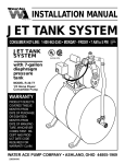
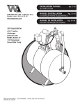
MODELS CPM18-40 AND CPM24-30 CPM SERIES INDUSTRIAL PUMPS INSTALLATION AND SERVICE MANUAL NOTE! To the installer: Please make sure you provide this manual to the owner of the equipment or to the responsible party who maintains the system. Part # 23833A273 | © 2014 Pentair Ltd. | 10/08/14 INSTRUCTIONS nozzles, or gun on and off to be sure that pressure adjustment and regulator operation are satisfactory. Nozzle capacity should not exceed 90% of pump capacity for satisfactory regulator operation. Avoid freezing by draining all water from pump and system in cold weather. There is a 3/8 NPT drain plug for each cylinder chamber. CAUTION: Positive displacement pumps must have a proper size and operable type of pressure regulating valve or pressure relief valve piped into the discharge line. This is mandatory to prevent damage to pump and piping or possible injury to personnel. Do not install any valves or shut-off devices in the bypass line from pressure regulator tank or supply. SUGGESTED MAINTENANCE SCHEDULE Check oil level – Daily CAUTION: All pumps should be installed level. For mobile applications the maximum angle of intermittent operation should be no more than 5° in any one direction. Drain & change oil – 300 hrs. Drain at operating temperature to prevent contamination from settling. CALIFORNIA PROPOSITION 65 WARNING: Inspect piston packing and spacer rings – 500 hrs. Inspect frequently for leakage; piston packing is allowed to drip in order to cool and lubricate packing. This product and related accessories contain chemicals known to the State of California to cause cancer, birth defects or other reproductive harm. Inspect valves and springs – 500 hrs. Replace if cracks and heavy wear are present. It is recommended to install a pulsation dampener in the discharge line to smooth out pressure pulse. This can protect pump parts and piping for longer life and quieter operation. Inspect connecting link bearing inserts – 1000 hrs. Replace at first signs of fatigue or wear to prevent damage to crankshaft. BELT DRIVE Inspect crankshaft tapered roller bearings and piston stud – 2000 hrs. Replace if there is any pitting on the seal surface or if the surface is rough. With belt drives the pulley on both the engines and pump should be located as close as possible to bearing to reduce bearing and shaft bending loads. Make sure that all bolts, nuts, set screws, and keys are properly tightened. On multiple V-belt drives, a complete set of new belts should be installed when making a replacement. LUBRICATION Pump – Fill crankcase with 2 quarts of oil. Maintain oil level between the high and the low level marks on bayonet oil gauge inserted through crankcase cover. Add extra quart for crankcase speeds under 300 rpm. STARTING PUMP Fill pump crankcase with recommended oil (SAE) to the level mark on oil saber. Replace all drain plugs in pump and piping. Inspect tank to be sure that no foreign material is in tank or suction line. Fill the tank at least half full or connect suction to water supply. Open valve (if present) in suction line. Avoid prolonged dry operation which may cause excessive wear on plunger packing. Be sure that an operating pressure gauge is located in the discharge line. Use heavy duty, liquid filled, pulsation free pressure gauge. Make sure all valves, including spray gun or nozzles, are open in discharge line. Spray gun may be anchored to discharge back into tank. Completely back off the pressure adjusting device on pressure regulating valve. Check pressure rating for pulsation dampener, pressure regulator and pipe fitting to make sure working pressure is not over maximum pressure rating. Drain oil from crankcase after first 30 hours of operation. Refill with proper oil. Check oil levels regularly. Change oil immediately if water droplets are found on bayonet gauge. SERVICE Disconnect electrical leads to motor or remove spark plug leads on engine before proceeding. PLUNGER SEAL SERVICE Remove the three seal lubricating lines and nuts holding the fluid end and slide head. Rotate crankshaft until plunger is flush with seal housing. Slide seal housing forward to clear plunger and remove. Remove seals and clean seal housing. Install new seal. Lubricate with waterproof grease and repeat steps to install plunger seal. fter starting, close discharge valve or spray gun A slowly while watching pressure gauge to make sure relief valve or unloader is operating properly. Adjust relief valve or unloader to desired pressure. Cycle 23833A273 10/08/14 2 VALVE SERVICE Measure the shim gap adjacent to each of the screws by inserting a flat feeler gauge in the gap until it bottoms out. The required shim thickness for this cap is equal to the average of the two gap measurements, plus .005" constant. When servicing valves always replace O-rings. Remove bolts and valve clamp. Remove valve cover on top of fluid access to valve components. Suction and discharge valve will show a wear pattern on seating surface but need not be replaced unless extreme wear, cracks or erosion is present on valve. All valves and seats are interchangeable but it is recommended to put them back in the same order as taken out if not renewing the components. To replace valve components, clean bores to remove corrosion or burrs, and lubricate and replace O-rings in bottom of bore. Lubricate valve seat and replace O-ring. On the valve, make sure the spring is inserted squarely before putting assembly into fluid end. Repeat for the discharge valve, insert valve cover and secure. Remove the two bolts and cap and place the correct shim thickness on this cap. If the required shim thickness does not match an .003" increment of a green shim, round up or down to the nearest .003" shim increment. Remove non-drive side bearing cap and place the 4.38" O.D. O-ring on the cap and reinstall. Tighten the screws as the crankshaft is fully rotated by hand to seat the bearings and so no significant binding results. SERVICING CONNECTING LINKS When the connecting link bearings are worn standard replacement bearing inserts can be installed in the connecting links. These bearings should not be tampered with or changed in size at the time of assembly. Do not change the size of the link by filing or grinding the faces. When reinstalling the links on the crankshaft be sure to place the oil holes upward for proper lubrication. REPLACING PISTON ROD SEALS The rod seal assembly contains two seals, and two oil seals with lips facing power end. The fluid end must be removed before the oil seal can be replaced. Unscrew Allen screws and place into the other two tapped holes. Gradually screw them in to push oil seal housing off the retainer. Assemble new seals in oil seal housing. An assembly thimble should be used on end of crosshead rod for sliding oil seal housing back into retainer. Check gasket replace if damaged. When installing new bushings for the wrist pin, these bushings should be reamed to proper size after pressing into the link. Do not ream "D" bushings. n assembly thimble should be used on small end of A the piston rod to expand sealing edge as it is pushed on. The thimble should be machined from high carbon steel and polished on the exterior to reduce possibility of seal lip damage. RECOMMENDED TORQUE (foot-pounds) FASTENER LOCATION Link Bearing Caps - 25 Crankshaft End Caps - 20 SERVICING CRANKCASE PARTS Capscrew Holding Piston - 20 To remove the crankcase you do not need to remove the cylinder body from the crankcase. Remove the connecting link caps from the connecting links and push the free links toward the cylinder end as far as possible. Take off the bearing caps and pull the crankshaft through the bearing opening. Packing Assembly to Piston Rod - 20 Valve and Cylinder Cover Clamps - 80 Capscrew (Fluid End to Crankcase) - 1/2"-50, 5/8"-85 CROSSHEAD AND PISTON RODS REPLACING CRANKSHAFT AND SHIMMING BEARINGS Repair parts for the crosshead and piston rod are supplied as a complete unit. If either of these parts becomes worn it is necessary to replace both the crosshead and piston rod. Under normal conditions a crosshead will not wear nor will the bore of the crankcase wear to the extent that replacement will be required. A clearance of .002" to .004" is standard for the crosshead. Remove bolts from both bearing caps. Carefully remove bearing cap, shims and O-rings and discard shims and O-rings. Inspect and clean shim surfaces on both bearing caps and crankcase. Slide crankshaft into the crankcase and rest bearings on the sides of the crankcase. Place .045" shim on the drive side bearing cap and place 4.38" O.D. O-ring onto the bearing cap. RECONDITIONING CRANKSHAFTS Cover key-way slot and slide the bearing cap with oil seal over the drive shaft. Tighten the cap screws. Install the non-drive side cap without shims or O-ring. Secure with cap screws and tighten alternately so the crankshaft can be fully rotated by hand to seat the tapered roller bearings. When crank pins are slightly damaged, they can sometimes be reconditioned for further use. This can be done with emery cloth and polishing until all ridges are completely removed. The final polishing operation should be performed by using a very fine emery cloth. 3 23833A273 10/08/14 This procedure can be followed only where the amount of sanding does not reduce the normal diameter of the crank pin. Worn or corroded crank pins can be ground and polished down to .030" under the size when the crank was new. The undersize bearing halves are made especially for turned down crankshafts. If the surface is badly damaged, the crankshaft can often be salvaged by metalizing the crank pins, regrinding and polishing to the original diameter. hen assembling bearings on the crankshaft, an oil seal W expander thimble should be used at the end of the shaft. A thimble of this type will cause the lip of the oil seal to gradually expand up to the shaft diameter allowing it to slip onto the shaft without turning or damaging the seal in any way. A slight nick or cut in the lip can damage a seal enough that it will not retain the oil properly. 23833A273 10/08/14 4 THE PUMP MUST BE INSTALLED WITH A PRESSURE RELIEF VALVE IN DISCHARGE LINE TROUBLESHOOTING Pump fails to build pressure with discharge closed Failure to hold pressure with discharge open Pump is noisy Pump gets hot Pressure gauge shows abnormal fluctuation Regulator chatter POSSIBLE CAUSE OF PROBLEM 1. Pump not primed 2. Valve closed in suction line X 3. Suction line or sediment chamber clogged X X 4. Air leak in suction line X X 5. Pressure regulator valve badly worn or not properly adjusted X 6. Pump packing or valves badly wornX X X 7. Pump cylinder body cracked X X 8. Holes in discs are too large X 9. Need suction surge arrester X 10. Water in crankcase X 11. Worn connecting link bearings X X 12. Lack of oil in crankcase X X 13. Foaming mixtureX X X 14. Regulator plunger stickingX 15. Unloader stuffing box nut too tightX 16. Foreign matter under pump valveX X X 17. Discharge surge arrester inoperative X X 18. Loose piston rod X 19. Improper preload of crankshaft bearings X X X X X X X X Explanation of the Service Chart 1. Pump priming is usually not necessary when the pump is installed correctly. However, there are certain conditions which may make it necessary to prime the pump to get the pumping action started. Priming will be required when it is impossible for the plunger to displace the air in the pump and replace it with water. This can be caused by a high suction lift, the valves being stuck on the seat or by valves sticking due to extreme corrosion. A pump will not prime readily if someone has tampered with the valve springs causing them to exert undue pressure of the valve plates against the valve seats. 3. A sediment chamber should be installed in the suction line between the gate valve and the pump suction. The strainers in the sediment chambers are sufficient to allow a free flow of liquid to the pump. If the strainers become severely clogged, they will completely stop the flow of liquid to the pump. 4. Any plunger pump operating at a high pressure will not perform properly nor quietly if a mixture of air and water is allowed to enter the pump suction. A small air leak in the suction line will cause the pump to knock and vibrate excessively by allowing the pump to draw a certain amount of water mixed with air on each stroke of the piston. A large air leak will cause the pump to lose prime after which it cannot be reprimed until the air leak is stopped. Air leaks may occur at the joints of the suction line piping, at the gate valve in the suction line, at the gasket sealing the cap on the sediment chamber, by a crack in the suction wall of the cylinder body, or by air drawing past the packing on the suction stroke if the packing is badly worn. 2. A gate valve is sometimes installed in the suction line between a tank or pressure line and the pump sediment chamber. It will shut off the supply source in order to clean the sediment chamber or to perform pump repairs. If this valve is partially or fully closed, it will interfere with the flow of water to the pump suction. This may cause severe knocking and vibration of the pump because the water cannot flow into the cylinder cavities fast enough. 5 23833A273 10/08/14 5. If the pressure regulator internal bypass valve is worn, it will allow too much of the pump capacity to be bypassed and recirculated back to the tank. By examining the flow from this valve with the discharge turned on, it can be determined whether or not the valve is worn. If a heavy flow continues when the discharge is turned on, it is usually a good indication of a worn valve and should be replaced. to heat the oil and other working parts, will not normally accumulate water by condensation. Replace the plunger cups as soon as they start to leak. 11.Worn connecting link bearings are caused by unusual or adverse operating conditions and are seriously affected by corrosion if water is present in the crankcase. They will wear out from overheating if adequate oil is not provided in the crankcase. It is recommended to drain, clean and refill with new oil prior to any storage period. Replace bearings as soon as any damage is discovered to avoid possible damage to crankshaft. 6. Worn plunger cups, valves or valve seats will cause a severe drop in pump capacity pressure. Worn plunger cups are detected by water leakage past the cups and should be replaced immediately. Water getting into the pump crankcase will cause severe corrosion of the bearings. Worn valves can only be detected by visual examination of each valve assembly. Abrasive liquid will cause wire cuts which begin as a very small groove, but increase rapidly once the valve starts to leak through this groove. If the valve plates are replaced as soon as they start to show this cutting action, it will prevent the valve seat from becoming cut in a similar manner. 12.Low oil in the crankcase can quickly cause failure of the pump's power end and result in extensive repairs. Oil level should be checked periodically during normal operation and during all maintenance work. 13.A foaming mixture will sometimes have the same effect as a small air leak in the suction line. This is because various quantities of the foam are drawn through the suction line into the pump disrupting the normal flow of water. 7. Pump cylinder bodies withstand an extreme amount of shock and pulsation while in operation, but if the pump is allowed to freeze, by not being drained, the freezing may crack the cylinder body walls in almost any location. If the crack occurs on the suction valve or cylinder portion of the body, it may allow a small amount of air to enter on the suction stroke and cause noisy operation or a decrease in pumping capacity. If the crack develops in the walls between the cylinder cavities or discharge valve cavity, it may allow the water to flow from one cavity to the adjacent cavity and cause uneven displacement. 14.Pressure regulators and unloading valves may become sluggish in action due to the plunger sticking or fitting too tightly in its cylinder. This may happen by an accumulation of chemicals collecting in and around the plunger or due to excessive corrosion of the plunger parts. To check this condition, remove and clean the plunger and cover the parts with a waterproof grease before assembling. 15.The stuffing box nut on the unloading valve lifting post should not be tightened to severely grip or bind the packing on the post. Tighten this nut just enough to prevent leakage and chatter. The pressure regulator and unloading valves may chatter or vibrate excessively due to an unstable operation from nozzling in the high or low capacity range of the regulator or unloader. The range should be at least 50% to 90% of pump capacity. With unloader valves, nozzle capacity should be at least 20% and not exceed 90% of pump capacity. 8. The holes in the gun or nozzle discs are continually subject to wear because of the high velocity of the liquid through the holes. If the holes become worn, they may allow a higher rate of discharge than the pump is able to provide, then a drop in pressure will be noticed. This can quickly be checked by reducing the number of nozzles or guns while watching the amount of overflow from the pressure regulator. If there is considerable overflow, it is an indication that the regulator valve is worn rather than the gun or nozzle disc. 16.If foreign matter becomes lodged between the pump valve and valve seat, a drastic drop in capacity and considerable surge or pulsation will occur in the discharge line. Examine each valve if this occurs. 9. Suction surge arresters should be installed on the suction line of reciprocating pumps, 1-1/2" or 2" can be used. A standing height of 12"-15" will be sufficient with the top end closed by an ordinary pipe cap. 17.When a pump is used for a long period of time, a waterlogged discharge surge could cause pulsation at the discharge. The suction should be opened to the atmosphere to allow air to be drawn through the pump to recharge the surge arrester. Do this with the pressure release valve open so the pump operates at no pressure. 10. Water may accumulate in the pump crankcase from two sources; leakage of the plunger cups or an accumulation of condensation/moisture inside the crankcase due to changes in weather or the repeated heating and cooling of the pump. Pumps used consistently, running for a considerable period of time 23833A273 10/08/14 6 18.Noisy pump operation can be caused by a loose plunger rod in the crosshead. This noise usually has a regular cadence timed with each stroke of the plunger. When this occurs, always replace both the rod and the crosshead. 19.Increased preload to the crankshaft bearings will reduce bearing life, require more power and generate more heat, while insufficient preload may cause a knock, timed with the crankshaft rotation. Check for loose bolts on the crankshaft end caps or adjust shims to obtain proper bearing preload. 7 23833A273 10/08/14 CPM 18-40 AND CPM 24-30 21 20 19 10 11 1 46 15 12 6 5 2 7 4 3 17 16 18 55 50 57 54 60 52 61 14 64 51 58 50 13 22 25 46 53 56 52 12 26 23 51 50 10 24 65 66 47 29 31 30 27 64 57 67 45 43 28 44 36 41 39 38 49 23833A273 10/08/14 59 8 40 42 32 33 34 35 11 9 48 64 62 63 37 8 CPM18-40 PLUNGER PUMP PARTS LIST (25905F000 STEEL) RIGHT–HAND CPM 18-40L PLUNGER PUMP PARTS LIST (25905F010 STEEL) LEFT–HAND CPM 24-30 PLUNGER PUMP PARTS LIST (25905F012) RIGHT-HAND Item 1 2 3 4 5 6 7 8 9 10 11 12 13 14 15 16 17 18 19 20 21 22 23 24 25 26 27 Eng. No. 05737A021 17995A001 110-000110-201 17360A014 19101A008 06077C000 06089B000 19101A013 10414B001 05011A027 05011A028 05674A019 17481A001 06076D000 27300B000 06074D011 06109A010K 06116A000 10414B002 05710A004 05818A077 17515B001 05030A020 05028A002 25927C000 25937E000 25934E000 25934E002 28 29 30 31 32 33 34 35 36 23188A002 06106A034 24959A002 22835A004 05059A435 06120A000 24958A001 05059A052 24894A007 24894A003 Description OIL FILL CAP OIL FILL NIPPLE O-RING OIL GAUGE SCREW, HEX 3/8 x 7/8 LID GASKET SCREW, HEX 3/8 x 1 CAP, BEARING CLOSED GASKET, SHIM .003" GREEN GASKET, SHIM .015" PINK BEARING CONE PLUG, MAGNETIC 1/2 CASE, GEAR LINK CRANKSHAFT BEARING, PAIR 2-3/8 PIN, CRK & WR CAP, BEARING OPEN SEAL, OIL WASHER, 1/4 CROSSHEAD & PISTON ROD WASHER, 1/4 SCREW COVER ADAPTER BODY, CYLINDER, 1018 STEEL BODY, CYLINDER, 1018 STEEL (FOR CPM-24-30) FITTING SCREW, SKT. HD #10 & 1/2 HOUSING CUP, U METRIC 22 GASKET SPRING RETAINER GASKET WASHER (FOR CPM 24-30) WASHER Qty. 1 1 1 1 6 1 1 12 1 6 4 2 1 1 3 1 3 3 1 1 4 3 4 4 1 1 1 1 Item 37 38 Eng. No. 14946A003 18922A009 39 25929A000 24794A005 43 25935A000 10519A002 25928B004 25928B000 24899A002 24899A004 25926B211 44 45 25926B200 05876A158 23265161275 40 41 42 10649A132 46 47 48 49 50 51 52 53 54 55 56 57 58 59 3 6 3 6 3 3 3 3 3 3 60 61 62 63 64 65 66 67 9 05675A018 05059A418 05876A224 05876A029 05876A159 05876A204 25931A000 25936A000 25930A000 25930A001 25932A000 25933B000 19105A042 25938A001 24793A006 24793A005 05659A125 19103A008 05659A120 26709A000 19109A047 05022A043 05022A016 05659A133 Description WASHER, SEAL 3/8 PACKING, V-RING & NITRILE (FOR CPM 24-30) PACKING, NITRILE & KEVLAR® RING, BOTTOM ADAPTER (FOR CPM 24-30) RING, BOTTOM ADAPTER FITTING PLATE (FOR CPM 24-30) PLATE SEAL (FOR CPM 24-30) SEAL PLUNGER, 1-1/4" DIA. (FOR CPM 24-30) PLUNGER, 1-1/4" DIA O-RING TUBE – # OF FT. (FOR CPM 18-40L) TUBE – # OF FT. (FOR CPM 18-40) BEARING CUP WASHER GASKET O-RING O-RING (FOR CPM 24-30) O-RING O-RING SEAT, VALVE VALVE SPRING, SUCTION VALVE SPRING, DISCHARGE VALVE CAP CLAMP SCREW, HEX 5/8 x 1-3/4 SET SCREW, SKT. DRV. 5/8-18 MALE ADAPTER (FOR CPM 24-30) MALE ADAPTER STUD, 5/8-18 x 3-1/4 SCREW, HEX 1/2 x 1-3/4 STUD, 5/8-18 x 8-1/2 WASHER, WEDGE NUT PLUG, PIPE, 1" NPT PLUG, PIPE, 1-1/2" NPT STUD, PLUNGER Qty. 12 3 3 3 3 3 3 3 3 3 3 3 3 2 3 2 3 3 3 3 9 6 6 3 3 3 1 9 2 3 3 4 4 4 2 9 1 1 3 23833A273 10/08/14 CPM 18-40ST PLUNGER PUMP PARTS LIST (25905F004 304 SST) RIGHT-HAND CPM 18-40STL PLUNGER PUMP PARTS LIST (25905F014 304 SST) LEFT-HAND CPM18-40SST PLUNGER PUMP PARTS LIST (25905F001 316 SST) RIGHT–HAND CPM 18-40SSTL PLUNGER PUMP PARTS LIST (25905F011 316 SST) LEFT–HAND Item 1 2 3 4 5 6 7 8 9 10 11 12 13 14 15 16 17 18 19 20 21 22 23 24 25 26 27 28 29 30 31 32 33 34 35 36 Eng. No. 05737A021 17995A001 110-000110-201 17360A014 19101A008 06077C000 06089B000 19101A013 10414B001 05011A027 05011A028 05674A019 17481A001 06076D000 27300B000 06074D011 06109A010K 06116A000 10414B002 05710A004 05818A077 17515B001 05030A020 05028A002 25927C000 25937E000 25934E004 25934E001 23188A002 06106A034 24959A002 22835A004 05059A435 06120A000 24958A001 05059A052 24894A003 23833A273 10/08/14 Description OIL FILL CAP OIL FILL NIPPLE O-RING OIL GAUGE SCREW, HEX 3/8 x 7/8 LID GASKET SCREW, HEX 3/8 x 1 CAP, BEARING CLOSED GASKET, SHIM .003" GREEN GASKET, SHIM .015" PINK BEARING CONE PLUG, MAGNETIC 1/2 CASE, GEAR LINK CRANKSHAFT BEARING, PAIR 2-3/8 PIN, CRK & WR CAP, BEARING OPEN SEAL, OIL WASHER, 1/4 CROSSHEAD & PISTON ROD WASHER, 1/4 SCREW COVER ADAPTER BODY, CYLINDER,304 SST (FOR CPM 18-40ST AND CPM 18-40STL) BODY, CYLINDER FITTING SCREW, SKT. HD #10 & 1/2 HOUSING CUP, U METRIC 22 GASKET SPRING RETAINER GASKET WASHER Qty. 1 1 1 1 6 1 1 12 1 6 4 2 1 1 3 1 3 3 1 1 4 3 4 4 1 1 1 1 3 6 3 6 3 3 3 3 3 10 Item 37 38 Eng. No. 14946A003 25929A000 39 40 41 25929A001 25935A000 10519A002 25928B000 42 25928B001 24899A004 43 44 24899A008 25926B200 05876A158 45 05876A205 10649A132 46 47 48 49 50 23265161275 05675A018 05059A418 05876A224 05876A159 05876A204 51 52 53 54 55 05876A206 25931A000 25936A000 25930A000 25930A001 25932A000 56 57 58 59 60 61 62 63 64 65 66 25932A001 25933B000 19105A042 25938A001 24793A005 05659A125 19103A008 05659A120 26709A000 19109A047 05022A043 05022A012 67 05022A016 05659A133 Description WASHER, SEAL 3/8 PACKING, NITRILE & KEVLAR® (FOR CPM 18-40ST AND CPM 18-40STL) PACKING, VITON® RING, BOTTOM ADAPTER FITTING PLATE (FOR CPM 18-40ST AND CPM 18-40STL) PLATE SEAL (FOR CPM 18-40ST AND CPM 18-40STL) SEAL PLUNGER, 1-1/4" DIA. O-RING (FOR CPM 18-40ST AND CPM 18-40STL) O-RING TUBE – # OF FT. (FOR CPM 18-40ST AND CPM 18-40STL) TUBE # OF FT. BEARING CUP WASHER GASKET O-RING O-RING O-RING (FOR CPM 18-40ST AND CPM 18-40STL) O-RING SEAT, VALVE VALVE SPRING, SUCTION VALVE SPRING, DISCHARGE VALVE CAP (FOR CPM 18-40ST AND CPM 18-40STL) CAP CLAMP SCREW, HEX 5/8 x 1-3/4 SET SCREW, SKT. DRV. 5/8-18 MALE ADAPTER STUD, 5/8-18 x 3-1/4 SCREW, HEX 1/2 x 1-3/4 STUD, 5/8-18 x 8-1/2 WASHER, WEDGE NUT PLUG, PIPE, 1" NPT PLUG, PIPE, 1-1/2" NPT (FOR CPM 18-40ST AND CPM 18-40STL) PLUG, PIPE, 1-1/2" NPT STUD, PLUNGER Qty. 12 3 3 3 3 3 3 3 3 3 3 3 1.5 1.5 2 3 3 3 9 9 6 6 3 3 3 3 1 9 2 3 4 4 4 2 9 1 1 1 3 CPM 18-40 AND CPM 24-30 BODY Rugged cast iron crankcase serves as oil reservoir. Removable cover section for easy service. PLUNGER ASSEMBY Solid stainless steel stud with TECH-23. VALVE ASSEMBLIES Stainless steel seats. Plastic acetal copolymer valves. CRANKSHAFT Rotates in either direction. Automotive-type heattreated alloy steel. MAIN BEARINGS Tapered roller bearings. SUCTION DISCHARGE OPENINGS Threaded for easy connections. CONTINUOUS SPLASH LUBRICATION In either rotation direction. BODY CP 18-40ST = 304 SST CP 18-40SST = 316 SST CPM 18-40 and CPM 24-30 = High Strength Steel CROSSHEADS Heavy-duty iron. “Pony” rods are axially threaded and pinned, polished stainless steel. CONNECTING LINKS Cast iron with replaceable bronze bearings. 1-3/8" DIA. SHAFT 5/16" SQ x 2" KEY 1 NPT DISCHARGE BOTH SIDES 11-1/4" 3-7/64" 3-1/2" 3-9/32" 2-7/8" 10-5/16" 3-1/4" 6-11/16" 10-7/8" 12-1/8" NOTE: 16-7/8" STANDARD SHAFT EXTENSION SHOWN (RIGHT HAND) 10-1/4" 12-1/2" 24-23/32" 1-1/2" NPT SUCTION BOTH SIDES Remove screw. Do not adjust screw for leveling. Screw is used for shipping only. 11 (4) MTG. SLOTS 9/16" DIA. 23833A273 10/08/14 STANDARD LIMITED WARRANTY CENTRIFUGAL & RECIPROCATING PUMPS Pentair Myers® warrants its products against defects in material and workmanship for a period of 12 months from the date of shipment from Pentair Myers or 18 months from the manufacturing date, whichever occurs first – provided that such products are used in compliance with the requirements of the Pentair Myers catalog and technical manuals. During the warranty period and subject to the conditions set forth, Pentair Myers, at its discretion, will repair or replace to the original user, the parts that prove defective in materials and workmanship. Pentair Myers reserves the right to change or improve its products or any portions thereof without being obligated to provide such a change or improvement for prior sold and/or shipped units. Seals, piston cups, packing, plungers, liners and valves used for handling clear, fresh, nonaerated water at a temperature not exceeding 120ºF are warranted for ninety days from date of shipment. All other applications are subject to a thirty day warranty. Accessories such as motors, engines and auxiliary equipment are warranted by the respective manufacturer and are excluded in this standard warranty. Under no circumstance will Pentair Myers be responsible for the cost of field labor, travel expenses, rented equipment, removal/reinstallation costs or freight expenses to and from the factory or an authorized Pentair Myers service facility. This limited warranty will not apply: (a) to defects or malfunctions resulting from failure to properly install, operate or maintain the unit in accordance with the printed instructions provided; (b) to failures resulting from abuse, accident or negligence; (c) to normal maintenance services and parts used in connection with such service; (d) to units that are not installed in accordance with applicable local codes, ordinances and good trade practices; (e) if the unit is moved from its original installation location; (f) if unit is used for purposes other than for what it is designed and manufactured; (g) to any unit that has been repaired or altered by anyone other than Pentair Myers or an authorized Pentair Myers service provider; (h) to any unit that has been repaired using non factory specified/OEM parts. Warranty Exclusions: PENTAIR MYERS MAKES NO EXPRESS OR IMPLIED WARRANTIES THAT EXTEND BEYOND THE DESCRIPTION ON THE FACE HEREOF. PENTAIR MYERS SPECIFICALLY DISCLAIMS THE IMPLIED WARRANTIES OF MERCHANTABILITY AND FITNESS FOR ANY PARTICULAR PURPOSE. Liability Limitation: IN NO EVENT SHALL PENTAIR MYERS BE LIABLE OR RESPONSIBLE FOR CONSEQUENTIAL, INCIDENTAL OR SPECIAL DAMAGES RESULTING FROM OR RELATED IN ANY MANNER TO ANY PENTAIR MYERS PRODUCT OR PARTS THEREOF. PERSONAL INJURY AND/OR PROPERTY DAMAGE MAY RESULT FROM IMPROPER INSTALLATION. PENTAIR MYERS DISCLAIMS ALL LIABILITY, INCLUDING LIABILITY UNDER THIS WARRANTY, FOR IMPROPER INSTALLATION. PENTAIR MYERS RECOMMENDS INSTALLATION BY PROFESSIONALS. Some states do not permit some or all of the above warranty limitations or the exclusion or limitation of incidental or consequential damages and therefore such limitations may not apply to you. No warranties or representations at any time made by any representatives of Pentair Myers shall vary or expand the provision hereof. 1101 MYERS PARKWAY ASHLAND, OHIO, USA 44805 419-289-1144 WWW.FEMYERS.COM Warranty Rev. 12/13