1
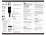
SKC
Ultraflo Calibrator
Operation Instructions
Catalog No. 709
P-MAN004-SKC ULTRAFLO MAN.
V8-96
16
P-MAN004-SKC ULTRAFLO MAN.
V8-96
1
P-MAN004-SKC ULTRAFLO MAN.
V8-96
2
P-MAN004-SKC ULTRAFLO MAN.
V8-96
15
WARRANTY
INSTRUCTION MANUAL
The Seller warrants to the Purchaser that any equipment manufactured by it and
bearing its name plate to be free from defects in material or workmanship,
under proper and normal use and service, as follows: if, at any time within
1 year from the date of sale, the Purchaser provides proof of purchase and
notifies the Seller that in his opinion, the equipment is defective, and returns
the equipment to the Seller's originating factory prepaid, and the Seller's
inspection finds the equipment to be defective in material or workmanship, the
Seller will promptly correct it by either, at its option, repairing any defective
part or material or replacing it free of charge. If inspection by the Seller does
not disclose any defect in material or workmanship, the Seller's regular charges
will apply. This warranty shall be effective only if installation and
maintenance is in accordance with our instructions and written notice of a
defect is given to the Seller within such period. This warranty is exclusive and
is in lieu of any other warranties, written, oral or implied; specifically, without
limitation, there is no warranty, of merchantability or fitness for any purpose.
The liability of the Seller shall be limited to the repair or replacement of
materials or parts as above set forth.
LIMITATION OF LIABILITY
The seller shall not be liable of any claim for consequential or special loss or
damage arising or alleged to have arisen from any delay in delivery or
malfunction or failure of the equipment. The Seller's liability for any other loss
or damage arising out of or connected with the manufacture, sale or use of the
equipment sold, including damage due to negligence, shall not in any event
exceed the price of the equipment supplied by us.
TABLE OF CONTENTS
SECTION
1
PAGE
ANALYSIS OF AIR FLOW CALIBRATION
a.
Physics of Measurements
b.
Accuracy of Gaseous Flow Measurements
2
3
2.
PRINCIPAL OF OPERATION and FEATURES
4
3.
START UP PROCEDURE
4.
CALIBRATION OF AIR FLOW SOURCES WITH THE Ultra-Flo
7
5.
MAINTENANCE OF THE Ultra-Flo CALIBRATOR
8
6.
VERIFICATION OF THE CALIBRATOR
9
7.
POWER SUPPLY
9
5-6
8. PRECAUTIONS/WARNINGS
10
9. PARTS LIST AND SERVICE
11
10. WARRANTY & LIMITATION OF LIABILITY
12
SKC Inc. reserves the right to make changes at any time, without notice, in
prices, colors, materials, specifications, and models; and to discontinue models.
COPYRIGHT PROTECTION OF DOCUMENT Copyright © 1993 SKC Inc.
This operating and service manual and the data enclosed herein are not to be
reproduced or used, in whole or in part, by anyone without the written
permission of SKC Inc.
P-MAN004-SKC ULTRAFLO MAN.
V8-96
14
©The UltraFlo CALIBRATOR® is the registered Trademark of SKC, Inc.
P-MAN004-SKC ULTRAFLO MAN.
V8-96
3
Section 1
Section 10
Analysis of Air Flow Calibration
a. Physics of Measurements:
At room temperature, all gases obey - to a very close approximation - the
ideal gas equation PV = nRT, where P is the pressure in newtons per square
meter, V is the volume in cubic meters, n is the number of moles of gas,
R is the empirically determined gas constant with the approximate value
8.31 joules/mole degrees Kelvin and T is the temperature in degrees Kelvin.
The method of measuring flow rates in the UltraFlo™ Calibrator is the
technique known as the soap film bubble test. A frictionless soap film is
suspended perpendicular to the air flow up a small bore tube. This film forms
a complete seal across the tube. The effect causes the soap film to move along
the tube at exactly the same rate as the air flow. Knowing a measured distance
and tube bore size, a volume can be calculated. Thus, a flow rate can be
determined by the movement of soap film across a fixed volume per unit of
time. This technique is classified as a Primary Standard.1
By comparing the four variables of the Ideal Gas Law against this detection
technique, the validity of measurement can be accessed. The volume (v) is
known and fixed therefore cannot change or be considered variable. The mass
(m) of the gas being measured is not changed in this technique as the soap film
is simply suspended across the tube cross section and moves with the gas flow
rate. Mass is not affected. This leaves pressure and temperature. These are
expressed by Boyle's Law P1V1 = P2V2 and Charles Law V2 / V1 = T2 / T1. No
pressure changes from the ambient during a test as the soap film is practically
frictionless. Temperature has no influence in this type of flow measurement
when all elements are at an ambient. This includes the Calibrating device, the
flow of gas and room temperature. These conditions are the general
circumstances in which tests are performed.
Conclusion: The detection method of measuring flow rates of gases over a
fixed volume per given unit of time is for all practical purposes independent of
all variables in the Ideal Gas Law. Thus, the UltraFlo serves as a primary
standard calibration method.
1
Lippman, Morton, "The Industrial Environment - its Evaluation and
Control," [U.S. Department of Health, Education and Welfare], NIOSH, 1973,
Ch 11, 101 pp
P-MAN004-SKC ULTRAFLO MAN.
V8-96
4
Ultra-Flo Parts List
Description
Catalog No.
UltraFlo Calibrator, 1 to 6000 ml/min
709
High Flow Calibrator, 100 ml to 30 L/min
710
UltraFlo Film Solution, 8 oz.
710-001
AC Charger/Adapter, 120 volt
709-01
AC Charger/Adapter, 230 volt
709-02
SERVICE POLICY:
Product to be serviced should be sent, freight prepaid, to:
SKC Inc.
National Service Center
863 Valley View Road
Eighty Four, PA 15330
Phone (412)941-9701
Fax (412)941-1369
Care should be taken in packaging to prevent damage in transit. Please include
a contact name and phone number, shipping address, and a brief description of
the problem. For non-warranty repairs, a purchase order number and billing
address is also required. The Service Center will contact customers with nonwarranty repairs with an estimate and authorization before proceeding with
repairs.
SKC Inc. will accept for repair any SKC product which is not contaminated
with hazardous materials. Product determined to be contaminated will be
returned unserviced.
P-MAN004-SKC ULTRAFLO MAN.
V8-96
13
Section 8
Precautions/Warnings
1.
Avoid the use of chemical solvents on flow cell, calibrator case and
faceplate. Generally, soap and water will remove any dirt.
2.
Never pressurize the flow cell at any time with more than 25 inches of
water pressure.
3.
Do not leave A/C adapter plugged into calibrator when not in use as this
could damage the battery supply.
4.
Hose fitting covers help to reduce evaporation of soap in the flow cell
when not in use.
5.
The UltraFlo Calibrator Soap is a precisely concentrated and sterilized
solution formulated to provide a clean, frictionless soap film bubble over
the wide, dynamic range of the calibrator. The sterile nature of the soap
is important in the prevention of residue build-up in the flow cell center
tube, which could cause inaccurate readings. The use of any other soap is
not recommended.
b. Accuracy of Gaseous Flow Measurements
To properly evaluate the accuracy of flowing gases, two parameters must be
considered. First, the steadiness of the flow rate must be known. Practically
every type of pump creates some pulsing of the flowing gases. Second, the
rate of flow can drift up and down over some range. Current battery powered
personal air sampling pumps use various techniques to dampen pulsing and
special circuitry to monitor pump speed, thereby, attempting to generate
constant and steady flows.
The UltraFlo is an automation of the "classic" technique of using a soap
film seal to measure flow over a predetermined volume in a known time.
A microprocessor, operating at 6 megahertz per second, detects the passing of
the soap film seal over the established flow tube volume and automatically
calculates the rate of flow. The typical apparatus, 1,000 ml buret using a
stopwatch, can be significantly reduced in size since the microprocessor can
detect and measure the speed at 80 microsecond intervals. Compare this speed
to a technician's response time. With good precision on a stopwatch, he or she
could be repeatable within 50,000 microsecond (0.05 seconds), 625 times
slower than the microprocessor.
Consider this analysis: 1,000 cc buret NIST traceable; 0.01 second stopwatch
crystal controlled with clock accurate to + 15 sec per month; 1,000 cc/min
steady flow source (constant flow + 1 cc/min)
Example: Measure the flow rate using 1,000 cc buret by a skilled technician.
All devices are at a constant room temperature.
Test
1
2
3
Time
60.06 sec
60.00
59.94
Actual Flow Rate
999.0 cc/min
1000
1001
Note: At 1,000 cc/min of flow + 0.06 is equal to 1 cc/min change or
+ 0.1 accuracy. Repeatability is strictly a function of the technician’s skill.
Mathematically, it would seem 0.1% accuracy could be obtained using this
large volume and a skilled technician with a 1,000cc/min. steady source. Of
course, if the volume is smaller than 1,000cc or the flow is faster, the percent
of accuracy is further reduced by this manual method.
To summarize, the accuracy of measuring air flow relies on quality
measurement tools such as NIST traceable buret and crystal control stopwatch.
A constant air flow source and a reliable method of detection are the final
requirements to achieve repeatable and accurate flow readings.
P-MAN004-SKC ULTRAFLO MAN.
V8-96
12
P-MAN004-SKC ULTRAFLO MAN.
V8-96
5
Section 2
Principle of Operation and Features
Section 6
a. Detection Principle:
The UltraFlo utilizes the principle of measuring the flow rate of gases over a
fixed volume per unit of time. A Quartz controlled timer is the timing device
and the fixed volume is located in the flow cell center tube. A microprocessor
measures the time for a frictionless soap film to travel from the first sensor to
the second sensor (infrared which detects the passage up the tube) and then
calculates the volume per unit of time. The results are displayed in flow rate,
cc/min. on a four digit liquid crystal display. The decimal point floats to
present the data in the proper range. The timer is capable of detecting a soap
film at 80 microsecond intervals. This speed allows under steady flow
conditions an accuracy of +/- 0.5% of any display. The unique flow cell can
create a soap film over a range of 1 cc/min. to 6,000 cc/min. The flow cell is
spillproof when properly filled.
Verification Of Calibration
The calibrator is factory calibrated using a standard traceable to National
Institute of Science and Technology (N.I.S.T.). Attempts to verify calibrator
against a glass one liter buret should be conducted at 1000 cc/min. for
maximum accuracy. The calibrator is linear throughout the entire range.
Section 7
Power For The UltraFlo Calibrator
b. Understanding the Display Results
A unique feature of the microcomputer software program is data display. On
initiation, UltraFlo display will present 0000's with no decimal point indicated.
A series of ---- are displayed while a test is in progress. During sequential
tests, the previous reading is added to the current test, divided in half, and
displayed. If the previous reading and current reading are different by more
than + 5% a series of EEEE's will flash four times on the display and then
display the actual last test result. The next flow readings will start this
averaging technique over again. If individual readings are desired without
averaging, the "ON" button may be pushed to reset the unit to "0000"
following each test. The flashing numbers on the display after a test are for
three seconds duration. The purpose is to allow sufficient time for the soap to
return to the bottom reservoir.
1.
The battery supply utilizes 4 Nicad Sub C batteries. The unit will operate
up to 8 hours on a fully charged battery. The unit may also be operated
directly from the AC charger when batteries are low.
2.
Low battery light will indicate the power supply is too low for accurate
results.
3.
Charge battery pack for 16 hours minimum using the standard charger
supplied with the unit.
4.
A special power saving feature is the Automatic Shut Off.
After 7 minutes of non-use, the UltraFlo will shut off automatically.
c. Battery saver
Another feature of the UltraFlo is the battery saver "automatic shut down". If
a test is not conducted within approximately 7 minutes from turn on, the
Calibrator will turn itself off. Continuous use of the batteries is rated at 8
hours. The unit may also be operated directly from the A/C charger when
batteries are low. All units should be given an initial 16 hour charge prior to
use. A low battery light will indicate when it is time to recharge the battery. If
stored for a period of 30 days or more, unit will require a 16 hour charge prior
to operation.
©The UltraFlo program is copyrighted to SKC Inc.
P-MAN004-SKC ULTRAFLO MAN.
V8-96
6
P-MAN004-SKC ULTRAFLO MAN.
V8-96
11
7.
8.
After a 3 second delay from the time the final sensor is tripped another
test can be performed.
Section 3
Start Up Procedure
Repeat Steps 5 through 8 for minimum of 3 tests.
A.
Read the previous section of Principle of Operation if unfamiliar with
device.
B.
Soap volume is not critical, therefore a measured amount is not
necessary. The proper amount is that which is sufficient to create a
bubble. Simply pour a small amount of soap through the bottom nipple
to thoroughly cover the bottom of the flow cell and attach air source to
nipple (bottom nipple for pressure, top nipple for vacuum). Excessive
amount of soap may cause a continuous stream of bubbles to go up the
center tube at high flows.
Note:
If difficulty is encountered in making a clean single soap film rise up the
center tube:
a. Check level of soap in flow cell (Section 3 C).
b. If soap is cloudy (not clear), change the soap solution and clean
flow cell.
Section 5
Maintenance Of Calibrator
General Information:
To clean the flow cell, simply remove the three screws holding the flow cell to
the bottom of the case. Remove the flow cell and gently flush with tap water.
To prevent scratching the acrylic flow cell, wipe "only" with a soft cloth. Do
not allow center tube, where sensors detect soap film to be scratched or get
dirty. NEVER clean with ACETONE. Use only soap and warm water. When
cleaning prior to storage, allow flow cell to air dry. Shake any access water
from cell prior to reattaching to base of UltraFlo.
If stubborn residue persists, remove the bottom plate. Squirt a few drops of
soap into slot between base and flow cell to ease removal. Gently insert a coin
or flat screw driver into the ridge between the bottom plate and chamber using
leverage around the circumference of the cell until the bottom plate is
removed. Upon realigning, note scribe mark near one of the screw inserts on
bottom plate and align this mark with scribe mark on flow cell near air hose
inlet. Again, wet O-ring with soap prior to installation.
To reassemble, realign flow cell in case with hose nipples pointing to back of
case and reinstall the three bottom screws.
P-MAN004-SKC ULTRAFLO MAN.
V8-96
10
P-MAN004-SKC ULTRAFLO MAN.
V8-96
7
Section 4
C.
Wet flow cell by connecting a pump flowing at 1000 to 2000 cc/min.
Initiate soap film up center tube by rapidly pressing button down and
releasing. Repeat this procedure until bubble doesn't break. The tube is
now wet and tests at any range may be conducted. One minute warm up
time is all that is required of the UltraFlo.
Calibration Of Air Flow Sources With The UltraFlo
The instructions relate to industrial hygiene air sampling. It, basically, applies
to any gases flow rate measurements.
1.
Start the pump and allow approximately 5 minutes to stabilize.
Perform this step before connecting to flow cell as air flow dries center
tube if bubbles are not initiated at intervals.
2.
Connect sampling medium to pump by obtaining proper hose adapters for
connecting tubing to flow cell.
The flow cell hose connectors will accept two common sizes of vinyl
tubing (1/4" and 5/16"). A “Luer” fitting is incorporated in the upper
hose connector. The upper port is for vacuum and the bottom
for pressure. When the upper port is connected to vacuum, the lower
port must be open to the atmosphere. Conversely, whern the lower port
is connected to pressure, the upper port must be open to free air.
Never make bubble test with bottom hose connected in series (in line
with sampling filter).
3.
Wet the flow cell as described in Section 3.
4.
Begin Calibration:
Depress plunger into cell and quickly release.
Different flow rate can require quicker or slower release of the button.
5.
Carefully observe the bubble passing through the sensor zone. Only a
single straight bubble, perpendicular to the tube wall, is necessary for an
accurate test. If several bubbles go up to the tube at once it will not effect
the test data because the first sensor will not reset until the final sensor
has been tripped. A good technique is to watch the bubble pass up the
tube to ensure a good test has been conducted.
6.
Observe the display. A number will be displayed. The decimal point
will be appropriately placed. Read section 2-b on features concerning
data display.
UltraFlo CALIBRATOR® PACKAGE
P-MAN004-SKC ULTRAFLO MAN.
V8-96
8
P-MAN004-SKC ULTRAFLO MAN.
V8-96
9