1
40MFC / 38MFC
40MFQ / 38MFQ
High---Wall Ductless Split System
Sizes 009 to 022
Service Manual
TABLE OF CONTENTS
PAGE
SAFETY CONSIDERATIONS . . . . . . . . . . . . . . . . . . . . . . . . . 1
INTRODUCTION . . . . . . . . . . . . . . . . . . . . . . . . . . . . . . . . . . . 1
MODEL / SERIAL NUMBER NOMENCLATURE . . . . . . . . . 2
STANDARD FEATURES AND ACCESSORIES . . . . . . . . . . . 3
SPECIFICATIONS -- COOLING ONLY (MFC) . . . . . . . . . . . . 4
SPECIFICATIONS -- HEAT PUMP UNITS (MFQ) . . . . . . . . . 5
DIMENSIONS . . . . . . . . . . . . . . . . . . . . . . . . . . . . . . . . . . . . . . 6
SERVICE VALVE LOCATIONS . . . . . . . . . . . . . . . . . . . . . . . . 6
CLEARANCES . . . . . . . . . . . . . . . . . . . . . . . . . . . . . . . . . . . . . 7
SYSTEM OPERATING ENVELOPE . . . . . . . . . . . . . . . . . . . . 8
ELECTRICAL DATA . . . . . . . . . . . . . . . . . . . . . . . . . . . . . . . . 8
WIRING . . . . . . . . . . . . . . . . . . . . . . . . . . . . . . . . . . . . . . . . . . . 9
CONNECTION DIAGRAMS . . . . . . . . . . . . . . . . . . . . . . . . . . 9
WIRING DIAGRAMS . . . . . . . . . . . . . . . . . . . . . . . . . . . . . . . 10
REFRIGERATION CYCLE DIAGRAM . . . . . . . . . . . . . . . . . 14
REFRIGERANT LINES . . . . . . . . . . . . . . . . . . . . . . . . . . . . . 15
SYSTEM EVACUATION AND CHARGING . . . . . . . . . . . . . 15
CONTROL SYSTEM . . . . . . . . . . . . . . . . . . . . . . . . . . . . . . . 16
SYSTEM SAFETIES . . . . . . . . . . . . . . . . . . . . . . . . . . . . . . . 17
SEQUENCE OF OPERATION . . . . . . . . . . . . . . . . . . . . . . . . 17
MODES OF OPERATION . . . . . . . . . . . . . . . . . . . . . . . . . . . . 18
TROUBLESHOOTING . . . . . . . . . . . . . . . . . . . . . . . . . . . . . . 20
APPENDIX . . . . . . . . . . . . . . . . . . . . . . . . . . . . . . . . . . . . . . . 32
severe personal injury or death. WARNING signifies hazards
which could result in personal injury or death. CAUTION is used
to identify unsafe practices which may result in minor personal
injury or product and property damage. NOTE is used to highlight
suggestions which will result in enhanced installation, reliability, or
operation.
WARNING
!
ELECTRICAL SHOCK HAZARD
Failure to follow this warning could result in personal
injury or death.
Before installing, modifying, or servicing system, main
electrical disconnect switch must be in the OFF
position. There may be more than 1 disconnect switch.
Lock out and tag switch with a suitable warning label.
!
EXPLOSION HAZARD
Failure to follow this warning could
result in death, serious personal injury,
and/or property damage.
Never use air or gases containing
oxygen for leak testing or operating
refrigerant compressors. Pressurized
mixtures of air or gases containing
oxygen can lead to an explosion.
SAFETY CONSIDERATIONS
Installing, starting up, and servicing air--conditioning equipment
can be hazardous due to system pressures, electrical components,
and equipment location (roofs, elevated structures, etc.).
Only trained, qualified installers and service mechanics should
install, start--up, and service this equipment.
Untrained personnel can perform basic maintenance functions such
as cleaning coils. All other operations should be performed by
trained service personnel.
When working on the equipment, observe precautions in the
literature and on tags, stickers, and labels attached to the
equipment.
Follow all safety codes. Wear safety glasses and work gloves. Keep
quenching cloth and fire extinguisher nearby when brazing. Use
care in handling, rigging, and setting bulky equipment.
Read this manual thoroughly and follow all warnings or cautions
included in literature and attached to the unit. Consult local
building codes and National Electrical Code (NEC) for special
requirements.
Recognize safety information. This is the
safety--alert symbol !! . When you see this symbol on the unit and
in instructions or manuals, be alert to the potential for personal
injury.Understand these signal words: DANGER, WARNING, and
CAUTION. These words are used with the safety--alert symbol.
DANGER identifies the most serious hazards which will result in
WARNING
!
CAUTION
EQUIPMENT DAMAGE HAZARD
Failure to follow this caution may result in equipment
damage or improper operation.
Do not bury more than 36 in. (914 mm) of refrigerant pipe
in the ground. If any section of pipe is buried, there must be
a 6 in. (152 mm) vertical rise to the valve connections on
the outdoor units. If more than the recommended length is
buried, refrigerant may migrate to the cooler buried section
during extended periods of system shutdown. This causes
refrigerant slugging and could possibly damage the
compressor at start--up.
INTRODUCTION
This Service Manual provides the necessary information to service,
repair, and maintain the 38--40MF family of Puron air conditioners
and heat pumps. Section 2 of this manual is an appendix with data
required to perform troubleshooting. Use the Table of Contents to
locate a desired topic.
MODEL / SERIAL NUMBER NOMENCLATURES
INDOOR UNIT
40
MFC
009
--- --- ---
1
Voltage
1 --- 115 ---1 ---60
3 --- 208 ---230 ---1 ---60
40= Fan Coil Unit
Nominal Capacity
009 --- 3/4 Ton
012 --- 1 Ton
017 --- 1 ---3/7 Ton (HP)
018 --- 1 ---1/2 Ton (AC)
022 --- 1 ---5/6 Tons
Unit Type
MFC --- Cooling Only
MFQ --- Heat Pump
OUTDOOR UNIT
38
MFC
009
--- --- ---
1
Voltage
1--- 115 ---1 ---60
3--- 208 ---230 ---1 ---60
38 = Air ---Cooled Condenser
Nominal Capacity
009 --- 3/4 Ton
012 --- 1 Ton
017 --- 1 ---3/7 Ton (HP)
018 --- 1 ---1/2 Ton (AC)
022 --- 1 ---5/6 Tons
Unit Type
MFC --- Cooling Only
MFQ --- Heat Pump
01
06
V
00001
Week of Manufacture
Serial Number
Manufacturing Site
Year of Manufacture
Use of the AHRI Certified
TM Mark indicates a
manufacturer’s
participation in the
program For verification
of certification for individual
products, go to
www.ahridirectory.org.
2
STANDARD FEATURES AND ACCESSORIES
Ease Of Installation
Mounting Brackets
Low Voltage Controls
Comfort Features
Microprocessor Controls
Wired Remote Control
Wireless Remote Control
Automatic Horizontal Air Sweep
Air Direction Control
Auto Restart Function
Cold Blow Protection On Heat Pumps
Freeze Protection Mode On Heat Pumps
Turbo Mode
Silence Mode
Auto Changeover On Heat Pumps
Energy Saving Features
Sleep Mode
Stop/Start Timer
Safety And Reliability
3 Minute Time Delay For Compressor
Over Current Protection For Compressor
Indoor Coil Freeze Protection
Indoor Coil High Temp Protection in Heating Mode
Condenser High Temp Protection in Cooling Mode
Ease Of Service And Maintenance
Cleanable Filters
Diagnostics
Liquid Line Pressure Taps
Application Flexibility
Condensate Pumps
Crankcase Heater
Legend
S Standard
A Accessory
S
S
S
A
S
S
S
S
S
S
S
S
S
S
S
S
S
S
S
S
S
S
S
A
S
INDOOR UNITS
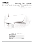
A07892
Fig. 1 – Condensate Pump Accessory
On high wall fan coils, the condensate pump has a lift capability of
12 ft (3.6 m) on the discharge side with the pump mounted in the
fan coil or 6 ft (1.8 m) on the suction side if the pump is remote
mounted. The pump is recommended when adequate drain line
pitch cannot be provided, or when the condensate must move up to
exit.
NOTE: An external 115v power source will be required to run the
pump on unit sizes 9k and 12k.
OUTDOOR UNITS
Crankcase Heater
Standard on all unit sizes. Heater clamps around compressor oil
stump.
3
SPECIFICATIONS -- COOLING ONLY UNITS (MFC SERIES)
System
Size (KBTU/Hr)
Outdoor Model
Indoor Model
AHRI Performance Ratings*
Cooling Rated Capacity Btu/h
Cooling Cap. Range Min - Max Btu/h
SEER
EER
Operating Range
Cooling Outdoor DB Min - Max °F
Cooling Indoor DB Min -Max °F
Controls
Wireless (°C, °F, Convertible)
Wired (°C, °F, Convertible)
Electrical
System Voltage-PH-Hz
Control Voltage
Power Supply
Outdoor - MCA
Outdoor - Fuse Rating (MOCP)
Outdoor Motor
Rpm/CFM
Diameter (in) ... No. of Blades
Motor (hp)
Capacitor (µF) / voltage
Indoor Motor
Motor Watts/ HP
Rpm/CFM (High)
Rpm/CFM (Medium)
Rpm/CFM (Low)
Blower Diameter / Length (in)
Capacitor (µF)
Refrigerant
Refrigerant Type
Design Pressure (PSIG)
Metering Device
Charge (lb)
Refrigerant Lines
Connection Type
Pipe Connection Size - Liquid (In) OD
Pipe Connection Size - Suction (In) OD
Condensate Drain OD / ID (in)
Maximum Piping Length (ft)
Max Lift (Fan Coil Above) (ft)
Max Drop (Fan Coil Below) (ft)
Compressor
Type
Model
Oil Charge (POE –oz (g))
Capacitor
Rated Current (RLA)
Locked Rotor Amp (LRA)
Outdoor Coil
Face Area (sq. ft.)
No. Rows
Fins per inch
Circuits
Indoor Coil
Face Area (sq. ft.)
No. Rows
Fins per inch
Circuits
Dimensions - Outdoor
Dimensions (W X H X D) In
Net Weight (lbs.)
Dimensions - Indoor
Dimensions (W X H X D) In
Net Weight (lbs.)
09
38MFC009---1
40MFC009---1
12
38MFC012---1
40MFC012---1
38MFC012---3
40MFC012---3
9,000
4,000-10,000
12,000
4,500-13,000
10
9
18
38MFC018---3
40MFC018---3
22
38MFC022---3
40MFC022---3
18,000
5,500-19,000
22,000
6,500-24,000
8.5
10
15
14 - 115
63 - 90
Standard - Convertible
Optional: KSACN0101CAC
115 -1 -60
208-230-1-60
0-15V DC
Indoor unit powered from outdoor unit
19
10
14
30
15
20
19
30
1000 / 945
940 / 945
860 / 1050
16.7 … 3
0.68
15.8 … 3
0.31
6 / 250V
15 / 0.02
1200 / 192
1050 / 160
900 / 131
0.33
2.5 / 400 - 450v
15 / 0.02
1200 / 230
1050 / 194
900 / 158
3.7 / 21.3
930 / 1390
18.3 … 3
0.72
2.5 / 450v
20 / 0.027
1200 / 232
1050 / 193
900 / 157
3
16
25
28 / 0.038
1200 / 348
1050 / 294
900 / 236
3.9 / 28.7
45 / 0.061
1200 / 547
1050 / 458
900 / 368
4.2 / 30.7
3
1.5
R410A
550
Capillary Tube in Outdoor Unit
1.43
1.87
1.34
2.60
Flare
1/4
3/8
3/8
5/8
1/2
0.65 / 0.63
65
98
25
25
30
30
Rotary
DA108X1C-20FZ3
16.9 (480)
45µF / 250VAC
6µF / 450VAC
5.3
10
4.10
1
DA130M1C-31FZ
DA150S1C-20FZ
17.6 (500)
None
3.95
14
6.10
1.5
9.7
17
7.67
11.16
2
21
2
4
2.53
2.98
1/2
20
1.61
5.29
2
4
5
21
2
58.4
35.8 x 23 x 13.2
61.7
34.9 x 25.4 x 14
76.0
38.0 x 29.7 x 15.6
98.1
26.8 x 10.0 x 7.0
15.4
30.3 x 10.0 x 7.4
16.5
35.6 x 10.8 x 7.8
19.8
40.6 x 12.4 x 8.6
26.4
*Air Conditioning, Heating & Refrigeration Institute
--- Ratings are net values reflecting the effects of circulating fan heat. Ratings are
based on: Cooling Standard: 80_F (26.67_C) db, 67_F (19.44_C) wb air
entering indoor unit and 95_F (35_C) db air entering outdoor unit. High
Temperature Heating Standard: 70_F (21.11_C) db air entering indoor unit and
47_F (8.33_C) db, 43_F (6.11_C) wb air entering outdoor unit.
--- Ratings are based on 25 ft. (7.62 m) of interconnecting refrigerant lines.
--- All system ratings are based on fan coil units operating at high fan speed.
Consult Specification tables for airflows at all available fan speeds.
Legend
SEER --EER
--MCA --MOCP ---
4
Seasonal Energy Efficiency Ratio
Energy Efficiency Ratio
Minimum Circuit Amps
Max. Over--- Current Protection
SPECIFICATIONS -- HEAT PUMP UNITS (MFQ SERIES)
System
Size (KBTU/Hr)
Outdoor Model
Indoor Model
AHRI Performance Ratings*
Cooling Rated Capacity Btu/h
Cooling Cap. Range Min - Max Btu/h
SEER
EER
Heating Rated Capacity Btu/h
Heating Cap. Range Min - Max Btu/h
HSPF
COP Btuh, W
Operating Range
Cooling Outdoor DB Min - Max °F
Heating Outdoor DB Min - Max °F
Cooling Indoor DB Min - Max °F
Heating Indoor DB Min - Max °F
Controls
Wireless (°C, °F, Convertible)
Wired (°C, °F, Convertible)
Electrical
System Voltage-PH-Hz
Control Voltage
Power Supply
Outdoor - MCA
Outdoor - Fuse Rating (MOCP)
Outdoor Motor
Rpm/CFM
Diameter (in) ... No. of Blades
Motor (hp)
Capacitor (µF)
Indoor Motor
Motor Watts/ HP
Rpm/CFM (High)
Rpm/CFM (Medium)
Rpm/CFM (Low)
Blower Diameter / Length (in)
Capacitor (µF)
Refrigerant
Refrigerant Type
Design Pressure (PSIG)
Metering Device
Charge (lb)
Refrigerant Lines
Connection Type
Pipe Connection Size - Liquid (In) OD
Pipe Connection Size - Suction (In) OD
Condensate Drain OD / ID (in)
Maximum Piping Length (ft)
Max Lift (Fan Coil Above) (ft)
Max Drop (Fan Coil Below) (ft)
Compressor
Type
Model
Oil Charge (POE –oz (g))
Capacitor
Rated Load Amps (RLA)
Locked Rotor Amp (LRA)
Outdoor Coil
Face Area (sq. ft.)
No. Rows
Fins per inch
Circuits
Indoor Coil
Face Area (sq. ft.)
No. Rows
Fins per inch
Circuits
Dimensions - Outdoor
Dimensions (W X H X D) In
Net Weight (lbs.)
Dimensions - Indoor
Dimensions (W X H X D) In
Net Weight (lbs.)
09
38MFQ009---1
40MFQ009---1
12
38MFQ012---1
40MFQ012---1
38MFQ012---3
40MFQ012---3
9,000
4,000-10,000
12,000
4,500-13,000
10.5
9,000
4,000-10,500
10
12,000
4,500-13,000
17
38MFQ017---3
40MFQ017---3
22
38MFQ022---3
40MFQ022---3
17,000
5,500-19,000
22,000
6,500-24,000
9
18,000
5,500-19,500
9.5
22,000
6,500-24,500
15
8.2
8.0
8.1
9.7
14 - 115
5 - 75
63 - 90
32 - 86
Standard - Convertible
Optional: KSACN0101CAC
115 -1 -60
208-230-1-60
0-15V DC
Indoor unit powered from outdoor unit
10
14
15
20
19
30
1000 / 945
15.8 … 3
0.31
6
15 / 0.02
1200 / 192
1050 / 160
900 / 131
940 / 945
0.33
2.5
15 / 0.02
1200 / 230
1050 / 194
900 / 158
3.7 / 21.3
20 / 0.027
1200 / 232
1050 / 193
900 / 157
3
16
25
860 / 1050
16.7 … 3
0.68
930 / 1390
18.3 … 3
0.72
28 / 0.038
1200 / 348
1050 / 294
900 / 236
3.9 / 28.7
45 / 0.061
1200 / 547
1050 / 458
900 / 368
4.2 / 30.7
3
1.5
R410A
550
Capillary Tube in Outdoor Unit
2.6
2.87
3.52
Flare
1/4
3/8
3/8
5/8
1/2
0.65 / 0.63
65
98
25
25
30
30
Rotary
DA108X1C-20FZ3
16.9 (480)
45µF / 250VAC
6µF / 450VAC
5.3
10
DA130M1C-31FZ
3.95
14
8.19
DA150S1C-20FZ
17.6 (500)
None
9.7
17
7.81
11
2
17
3
18
4
2.53
2.98
1/2
1.61
5.29
2
2
4
5
35.8 x 23 x 13.2
70.5
34.9 x 25.4 x 14
82.7
38.0 x 29.7 x 15.6
103.6
35.6 x 10.8 x 7.8
19.8
40.6 x 12.4 x 8.6
26.4
20
21
26.8 x 10.0 x 7.0
15.4
*Air Conditioning, Heating & Refrigeration Institute
--- Ratings are net values reflecting the effects of circulating fan heat. Ratings are
based on: Cooling Standard: 80_F (26.67_C) db, 67_F (19.44_C) wb air
entering indoor unit and 95_F (35_C) db air entering outdoor unit. High
Temperature Heating Standard: 70_F (21.11_C) db air entering indoor unit and
47_F (8.33_C) db, 43_F (6.11_C) wb air entering outdoor unit.
--- Ratings are based on 25 ft. (7.62 m) of interconnecting refrigerant lines.
--- All system ratings are based on fan coil units operating at high fan speed.
Consult Specification tables for airflows at all available fan speeds.
30.3 x 10.0 x 7.4
16.5
Legend
SEER --EER
--HSPF --COP
--MCA --MOCP ---
5
Seasonal Energy Efficiency Ratio
Energy Efficiency Ratio
Heating Seasonal Performance Factor
Coefficient of Performance
Minimum Circuit Amps
Max. Over--- Current Protection
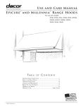
DIMENSIONS -- INDOOR
A14343
Unit Size
W in (mm)
D in (mm)
H in (mm)
9K
26.8 (680)
7.0 (178)
10.0 (255)
Operating Weight lb (kg)
15.4 (7)
12K
30.3 (770)
7.4 (188)
10.0 (255)
16.5 (7.5)
17K HP / 18K AC
35.6 (905)
7.8 (198)
10.8 (275)
19.8 (9)
22K
40.6 (1030)
8.6 (218)
12.4 (315)
26.4 (12)
DIMENSIONS - OUTDOOR
L2
D
L1
A14344
Model
W in (mm)
D in (mm)
H in (mm)
L1 in (mm)
L2 in (mm)
9K/12K
17K HP / 18K AC
22K
30.7 (780)
29.9 (760)
33.3 (845)
9.8 (250)
11.2 (285)
12.6 (320)
21.2 (540)
23.2 (590)
27.6 (700)
21.6 (549)
20.9 (530)
22.1 (560)
10.9 (276)
11.4 (290)
13.2 (335)
Operating
Weight lb (kg)
70.5 (32.0)
82.7 (37.5)
103.6 (47.0)
SERVICE VALVE LOCATIONS
22K
17/18K
9/12K
K
J
K
J
J
K
A14408
Service Valve Locations
J
K
9K
in. (mm)
4.37 (111)
4.61 (117)
12K
in. (mm)
4.37 (111)
4.61 (117)
6
18K
in. (mm)
4.09 (104)
6.34 (161)
22K
in. (mm)
4.13 (105)
4.13 (105)
CLEARANCES -- INDOOR
CEILING
6" (0.15m) min.
5"
(0.13m)
min.
5"
(0.13m)
min.
6' (1.8m)
FLOOR
A07891
Fig. 2 – Indoor Unit Clearance
CLEARANCES - OUTDOOR
A
Air-inlet
E
D
B
C
Air-outlet
A07894
Minimum Value
in. (mm)
24 (610)
24 (610)
80 (2032)
12 (305)
24 (610)
UNIT
A
B
C
D
E
Fig. 3 – Outdoor Unit Clearance
7
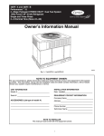
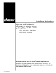
SYSTEM OPERATING ENVELOPE
-23
-18
-13
-8
-3
2
Outdoor Temperature (°C)
12
17
22
27
7
32
37
42
47
52
57
120
49
110
44
39
100
Indoor Temperature (°F)
5°F
34
115 °F
90°F
75°F
86°F
29
80
Cooling Connuous
Operaon
24
70
19
63 °F
Indoor Temperature (°C)
14°F
90
60
14
50
9
Heang Connuous
Operaon
40
4
32°F
30
-10
0
10
20
30
40
50
60
70
80
-1
90
100
110
120
130
140
Outdoor Temperature (°F)
NOTE: If the system operates beyond the conditions presented in this envelope, certain safety protection features may operate
and cause the system to operate abnormally. Optimum performance will be achieved during this operating temperature envelope.
A14466
Fig. 4 – System Operating Envelope
ELECTRICAL DATA
OPER.
UNIT SIZE
9K
12K
VOLTAGE
COMPRESSOR
018K (AC)
22K
INDOOR FAN
MCA
MAX FUSE
CB AMP
15
19
30
0.027
20
10
15
0.038
28
14
20
0.061
45
16
25
MAX / MIN*
RLA
LRA
V --- PH--- HZ
FLA
HP
W
V --- PH--- HZ
FLA
HP
W
127 / 104
115--- 1---60
5.3
10
115---1---60
0.7
0.31
23
115---1---60
0.3
0.020
5.3
10
0.3
0.33
24
0.2
253 / 187
208---230---1---60
3.95
14
0.6
0.68
50
0.3
9.7
17
0.6
0.72
53
0.4
12K
017K (HP)
OUTDOOR FAN
V --- PH--- HZ
208---230---1---60
*Permissible limits of the voltage range at which the unit will operate satisfactorily
LEGEND
FLA --- Full Load Amps
LRA --- Locked Rotor Amps
MCA --- Minimum Circuit Amps
RLA --- Rated Load Amps
8
208---230---1---60
WIRING
Recommended Connection Method for Power and Communication Wiring (To minimize communication wiring interference)
Power Wiring:
The main power is supplied to the outdoor unit. The field supplied
connecting cable from the outdoor unit to indoor unit consists of
three (3) wires and provides the power for the indoor unit. Two
wires are high voltage AC power and one is a ground wire.
Consult your local building codes and the NEC (National
Electrical Code) or CEC (Canadian Electrical Code) for special
requirements.
All wires must be sized per NEC or CEC and local codes. Use
Electrical Data table MCA (minimum circuit amps) and MOCP
(maximum over current protection) to correctly size the wires and
the disconnect fuse or breakers respectively.
Per caution note, only copper conductors with a minimum 300 volt
rating and 2/64--inch thick insulation must be used.
Communication Wiring:
A separate shielded copper conductor only, with a minimum 300
volt rating and 2/64--inch thick insulation, must be used as the
communication wire from the outdoor unit to the indoor unit.
To minimize voltage drop of the control wire, use the following
wire size and maximum lengths shown in the chart below:
Consult your local building codes and the NEC (National
Electrical Code) or CEC (Canadian Electrical Code) for special
requirements. All power wires must be sized per NEC or CEC and
local codes. Use Electrical Data table MCA (minimum circuit
amps) and MOCP (maximum over current protection) to correctly
size the wires and the disconnect fuse or breakers respectively.
Per caution note, only copper conductors with a minimum 300 volt
rating and 2/64--inch thick insulation must be used.
EQUIPMENT DAMAGE HAZARD
Failure to follow this caution may result in equipment
damage or improper operation.
S Wires should be sized based on NEC and local codes.
S Use copper conductors only with a minimum 300 volt
rating and 2/64 inch thick insulation.
18 AWG
16 AWG
Alternate Connection Method for Power and Communication
Wiring (May not prevent communication wiring interference)
The main power is supplied to the outdoor unit. The field supplied
connecting cable from the outdoor unit to indoor unit consists of
four (4) wires and provides the power and communication signals
for the indoor unit. Two conductors are for power wiring (L1/L2,
or L/N), one is a ground wire, and one is a DC communication
wire.
CAUTION
!
EQUIPMENT DAMAGE HAZARD
Failure to follow this caution may result in equipment
damage or improper operation.
S Be sure to comply with local codes while running wire
from indoor unit to outdoor unit.
S Every wire must be connected firmly. Loose wiring
may cause terminal to overheat or result in unit
malfunction. A fire hazard may also exist. Therefore,
be sure all wiring is tightly connected.
S No wire should be allowed to touch refrigerant tubing,
compressor or any moving parts.
S Disconnecting means must be provided and shall be
located within sight and readily accessible from the air
conditioner.
S Connecting cable with conduit shall be routed through
hole in the conduit panel.
Length
ft (m)
50 (15)
50 (15) to 100 (30)
Wire Size
CAUTION
!
The main power is supplied to the outdoor unit. the field supplied
connecting cable from the outdoor unit to indoor unit consists of
four wires and provides the power for the indoor unit as well as the
communication signal between the outdoor unit and indoor unit.
Two wires are high voltage AC power (L1 and L2), one is a
ground wire, and one is a DC communication wire.
CONNECTION DIAGRAMS
115-1-60
FIELD POWER SUPPLY
CONNECTING CABLE
OUTDOOR TO INDOOR
208-230-1-60
FIELD POWER SUPPLY
CONNECTING CABLE
OUTDOOR TO INDOOR
GND
GND
1(L)
L
N
Indoor Unit
Power Supply
115-1-60
S
Indoor
Signal
High
Voltage
GND
Ground
9K and 12k 115v INDOOR UNIT
2(N)
Power to
Indoor Unit
115-1-60
S
Indoor
Signal
High
Voltage
L
N
Main
Power Supply
115-1-60
9K and 12k 115v OUTDOOR UNIT
L1
L1
L2
Indoor Unit
Power Supply
115-1-60
S
Indoor
Signal
High
Voltage
GND
Ground
12K to 22K 208-230V INDOOR UNIT
L2
Power to
Indoor Unit
208-230-1-30
S
Indoor
Signal
High
Voltage
L1 L2
Main
Power Supply
208-230-1-30
12K to 22K 208-230V OUTDOOR UNIT
Notes:
1. Do not use thermostat wire for any connection between indoor and outdoor units.
2. All connections between indoor and outdoor units must be as shown. The connections are sensitive to polarity and will result in a fault code.
Fig. 5 – Connection Diagrams
9
A14506
10
BLACK
RED
BLUE
L-B(CN36)
N-B
BLUE
CS
L2
CN16
BLACK BLACK
L-A(CN37)
U
V
W
OUTDOOR WIRING DIAGRAM
Y/G
U
V
W
2020375A5475
WIRING DIAGRAMS
RED
CN9
REACTOR
RED
CN8
4
N-A
RY3
CN15
Y/G
L N S GND
Y/G
N
Power Input
Y/G
N
L
Dashed frame
parts only for heat
pump model.
HEATER,
T
CRANKCASE
L N S
CO DE
L_IN
CN11
CN16
CN6
CN4
CN5
P_1
CN8
CN9
CN10A
CN1
CN14
CN15
CN16
CN10
CN19
CN33
CN34
CN26,CN28
CN4
CN5
CN6
CN7
CN8,CN9
CN36,CN37
N- B
CN17
UV W
GND
YE LL OW
P_1
L_IN
6
4
3
Optional
CN5
5
M
CN10A
CN9
CN8
INDOOR WIRING DIAGRAM
CN16
CN11
CN 2
3(2)
M
~
8
DISPLAY BOARD
P ART NAME
FireWire L input terminal
Zero line N input terminal
Internal and external communication line interface
Indoor fan interface
Fan feedback interface
Stepper motor interface
Ground interface
Room temperature sensor interface
Pipe temperature sensor interface
Display interface
Electronic expansion valve interface
Compressor top temperature sensor (optional)
Exhaust temperature sensor
Outdoor temperature & amp; condenser pipe temperature sensor
DC fan output port (no)
AC fan output port
Electric heating wire line N
Electric heating wire line L
Four way valve control port
Power L input terminal
Power N input terminal
Ground wire
Communication line
Reactor connected line port
PFC capacitor connected line port
Power L input terminal
Test panel interface
Compressor connection port
Fig. 6 – Wiring Diagram 38/40MFC/MFQ009 / 38/40MFC/MFQ012 (115V)
5
CN10(CN19)
CN6
BROWN
BLUE
CN4
YELLOW
CN7
BLACK
RED
CN5
CN26
CN28
CN33
CN34
RED
2020325B3267
FAN C APAC ITOR BOARD
11
BLACK
RED
BLUE
CN2
BLACK
BLACK
U
V
W
CN3
OUTDOOR WIRING DIAGRAM
Y/G
U
V
W
20 20 37 5A54 77
B
L2
CS
BLACK
BLACK
BLUE
CN16
WHITE
WIRING DIAGRAMS (CONT.)
4
N-A
RY3
CN15
CN6
WHITE
5
Y/G
L N S GND
Power Input
Y/G
N
L
Dashed frame
parts only for heat
pump model.
HEATER,
T
CRANKCASE
L1 L2 S
CO DE
L_IN
CN11
CN16
CN6
CN4
CN5
P_1
CN8
CN9
CN10A
CN14
CN15
CN16
CN26,CN28
CN10
CN32,CN34
CN31,CN33
CN4
CN5
CN6
CN7
N- B
CN2,CN3
CN17
UV W
GND
YE LL OW
RED
2020328A7163
Fig. 7 – Wiring Diagram 38/40MFC/MFQ012 (208--230V)
Y/G
BROWN
BLUE
CN4
YELLOW
CN7
BLACK
RED
CN5
CN26
CN28
CN33
CN34
CN10
L_IN
3
Optional
CN5
5
CN10A
CN9
CN8
INDOOR WIRING DIAGRAM
CN16
CN11
CN2
~
M
8
DISPLAY BOARD
P ART NAME
FireWire L input terminal
Zero line N input terminal
Internal and external communication line interface
Indoor fan interface
Fan feedback interface
Stepper motor interface
Ground interface
Room temperature sensor interface
Pipe temperature sensor interface
Display interface
Compressor top temperature sensor (optional)
Exhaust temperature sensor
Outdoor temperature & condenser pipe temperature sensor
Four way valve control port
AC fan output port
Electric heating wire line N
Electric heating wire line L
Power L input terminal
Power N input terminal
Ground wire
Communication line
Power L input terminal
Reactor connected line port
Test panel interface
Compressor connection port
P_1
3(2)
M
12
BLACK
RED
BLUE
U
V
W
CN 103
CN 102
BLACK
CN11
REACTOR
BLACK
CN22
L2
CS
AMBIENT HEAT EXCHANGER SENSOR
SENSOR (BLACK)
DISCHARGE SENSOR
(WHITE)
OUTDOOR WIRING DIAGRAM
Y/G
U
V
W
2020378A3515
WIRING DIAGRAMS (CONT.)
BROWN
CN 13
Y/G
L N S GND
Power Input
Y/G
N
L
Dashed frame
parts only for heat
pump model.
HEATER, CRANKCASE
T
L1 L2 S
CO DE
L_IN
CN11
CN16
CN6
CN4
CN5
P_1
CN8
CN9
CN10A
CN101
CN102
CN103
CN8,CN9
CN10
CN4
CN7
CN13
CN12
CN14
CN15
N- B
CN11,CN22
UV W
GND
YE LL OW
RED
Fig. 8 – Wiring Diagram 38/40MFC018 -- 38/40MFQ017 (208--230V)
OUTDOOR
FAN
5(3)
CN10(CN10A)
Y/G
BLUE
CN 14
YELLOW
CN 12
BLACK
RED
CN 15
CN 9
CN 8
CN 7
CN 4
2020328A7163
L_IN
3
Optional
CN5
5
CN10A
CN9
CN8
INDOOR WIRING DIAGRAM
CN16
CN11
CN2
~
M
8
DISPLAY BOARD
P ART NAME
FireWire L input terminal
Zero line N input terminal
Internal and external communication line interface
Indoor fan interface
Fan feedback interface
Stepper motor interface
Ground interface
Room temperature sensor interface
Pipe temperature sensor interface
Display interface
Compressor top temperature sensor (optional)
Exhaust temperature sensor
Outdoor temperature & condenser pipe temperature sensor
Four way valve control port
AC fan output port
Electric heating wire line N
Electric heating wire line L
Power L input terminal
Power N input terminal
Ground wire
Communication line
Power L input terminal
Reactor connected line port
Compressor connection port
P_1
3(2)
M
13
OUTDOOR WIRING DIAGRAM
WIRING DIAGRAMS (CONT.)
L-OUT
Dashed frame
parts only for heat
pump model.
CS
20 20 37 9A41 84
HEATER, C RANKC ASE
Y/G
RED
Y/G
N
L
Power Input
BLUE
BLACK YELLOW
L N S GND
RED
Fig. 9 – Wiring Diagram 38/40MFC(Q)022 (208--230V)
Y/G
CN30
S
YELLOW
YELLOW
L1 L2 S
CO DE
L_IN
CN11
CN16
CN6
CN4
CN5
P_1
CN8
CN9
CN10A
CN12
CN7
CN17
CN1,CN2
CN11,CN22
CN10,CN13
CN5
CN6
CN3
CN4
P1
CN15
N- OUT1
RY2 POWER
CN26
CN4
CN5
CN2 CN3
CN11
CN12
CN1
CN6
UV W
GND
YE LL OW
RED
2020328A7163
L_IN
Optional
CN5
5
CN10A
CN9
CN8
INDOOR WIRING DIAGRAM
CN16
CN11
CN2
3
M
8
DISPLAY BOARD
P ART NAME
FireWire L input terminal
Zero line N input terminal
Internal and external communication line interface
Indoor fan interface
Fan feedback interface
Stepper motor interface
Ground interface
Room temperature sensor interface
Pipe temperature sensor interface
Display interface
Compressor top temperature sensor (optional)
Exhaust temperature sensor
Outdoor temperature & condenser pipe temperature sensor
Four way valve control port
AC fan output port
Fan capacitor port
Electric heating wire line N
Electric heating wire line L
Power L input terminal
Power N input terminal
Ground wire
Communication line
Power N Onput terminal
Power L Onput terminal
Test panel interface
Power L input terminal
Power N input terminal
Reactor connected line port
Bus voltage positive terminal
Bus voltage positive terminal
Main control board and power supply
Standby power interface
Compressor connection port
P_1
3(2)
M
~
REFRIGERATION CYCLE DIAGRAMS
FIELD
PIPING
FLARE CONNECTION
TWO PHASE
LIQUID LINE
CAPILLARY TUBE
SERVICE VALVE
HEAT
EXCHANGER
(CONDENSER)
HEAT
EXCHANGER
(EVAPORATOR)
SERVICE VALVE W/GAUGE PORT
SUCTION LINE
FLARE CONNECTION
COMPRESSOR
FIELD
PIPING
A08104
Fig. 10 – Cooling
INDOOR UNIT
OUTDOOR UNIT
FLARE CONNECTION
CHECK VALVE
(HEATING MODEL ONLY)
LIQUID
LIQUID HTG
SERVICE VALVE
TWO PHASE
CAPILLARY TUBE
HEAT
EXCHANGER
(CONDENSER)
HEAT
EXCHANGER
(EVAPORATOR)
SERVICE VALVE
W/ GAUGE PORT
SUCTION
DISCHARGE
REVERSING
VALVE
SUCTION
ACCUMULATOR
FLARE CONNECTION
(HEAT PUMP ONLY)
COMPRESSOR
FIELD
PIPING
COOLING
HEATING
A08105
Fig. 11 – Heat Pumps
14
REFRIGERANT LINES
Long Line Applications, 38MFC Units:
General refrigerant line sizing:
1 The 38MFC/MFQ units are shipped with a full charge of
R410A refrigerant. All charges, line sizing, and capacities
are based on runs of 25 ft (7.6 m). For runs over 25 ft (7.6
m), consult long--line section on this page for proper charge
adjustments.
2 Minimum refrigerant line length between the indoor and
outdoor units is 10 ft. (3 m).
3 Refrigerant lines should not be buried in the ground. If it is
necessary to bury the lines, not more than 36--in (914 mm)
should be buried. Provide a minimum 6--in (152 mm)
vertical rise to the service valves to prevent refrigerant
migration.
4 Both lines must be insulated. Use a minimum of 1/2--in.
(12.7 mm) thick insulation. Closed--cell insulation is
recommended in all long--line applications.
5 Special consideration should be given to isolating
interconnecting tubing from the building structure. Isolate
the tubing so that vibration or noise is not transmitted into
the structure.
IMPORTANT: Both refrigerant lines must be insulated
separately.
S
The following maximum lengths are allowed:
REFRIGERANT LINE LENGTHS ft. (m)
Max Elevation
Max Elevation
Max Line Length
(ID over OD)
(OD over ID)
Unit Size
9K
12K
17K HP
18K AC
22K
S
65 (20)
65 (20)
65 (20)
65 (20)
98 (30)
25 (8)
25 (8)
30 (10)
30 (10)
30 (10)
Unit
Size
9K
12K
18K AC
17K HP
22K
PIPE SIZES (in)
Mix Phase
1/4
1/4
1/4
1/4
3/8
Vapor
3/8
1/2
1/2
1/2
5/8
Unit Size
1.34 (0.61)
1.43 (0.65)
NA
1.87 (0.85)
2.60 (1.18)
2.60 (1.18)
2.60 (1.18)
2.87 (1.30)
NA
3.52 (1.60)
Above charge is for piping runs up to 25 ft. (7.6 m).
For piping runs greater than 25 ft. (7.6 m), add
refrigerant up to the allowable length as specified
below:
ADDITIONAL REFRIGERANT CHARGE
Unit Size
oz./ft. (g/m)
9K --- 18K
22K
Min
Max
Additional Charge, oz/ft.
ft (m)
10 --- 25
>25 --- 65
>65 --- 98
(3 --- 8)
(8 --- 20)
(20 --- 30)
65
10
0.16
None
98
0.32
0.32
Cooling:
9&12K
18&22K
Heating:
9&12K
17&22K
25 (7.5)
1%
1%
1%
1%
Capacity,% Loss
Line Length ft (m)
33 (10)
49 (15)
65 (20)
2%
5%
7%
2%
4%
6%
2%
2%
7%
6%
11%
10%
98(30)
--8%
--15%
SYSTEM EVACUATION AND
CHARGING
!
CAUTION
UNIT DAMAGE HAZARD
Failure to follow this caution may result in equipment
damage or improper operation.
Never use the system compressor as a vacuum pump.
Refrigerant tubes and indoor coil should be evacuated using the
recommended deep vacuum method of 500 microns. The alternate
triple evacuation method may be used if the procedure outlined
below is followed. Always break a vacuum with dry nitrogen.
SYSTEM VACUUM AND CHARGE
REFRIGERANT CHARGE lb. (kg)
Air Conditioner (AC)
Heat Pump (HP)
9K
12K
17K HP
18K AC
22K
Total Line
Length ft
3 Reduction in capacity due to long lines can be calculated
from the chart below.
CAPACITY LOSS
25 (8)
25 (8)
30 (10)
30 (10)
30 (10)
Refrigerant Charge
S
ADDITIONAL CHARGE TABLE
The following are the piping sizes.
Unit Size
9K
12K
17K HP
18K AC
22K
S
S
1 No change in line sizing is required.
2 Add refrigerant per table below.
0.16 (15)
0.32 (30)
Capillary tubes in outdoor unit are used as metering
devices.
Using Vacuum Pump
1 Completely tighten flare nuts A, B, C, D, connect manifold
gage charge hose to a charge port of the low side service
valve. (See Fig. 12.)
2 Connect charge hose to vacuum pump.
3 Fully open the low side of manifold gage. (See Fig. 13)
4 Start vacuum pump
5 Evacuate using either deep vacuum or triple evacuation
method.
6 After evacuation is complete, fully close the low side of
manifold gage and stop operation of vacuum pump.
7 The factory charge contained in the outdoor unit is good for
up to 25 ft. (8 m) of line length. For refrigerant lines longer
than 25 ft (8 m), add refrigerant as specified in the ADDITIONAL REFRIGERANT CHARGE table in this document.
8 Disconnect charge hose from charge connection of the low
side service valve.
9 Fully open service valves B and A.
10 Securely tighten caps of service valves.
15
Indoor Unit
Refrigerant
Outdoor Unit
A
Low Side
B
High Side
C
D
Service Valve
A07360
Fig. 12 – Service Valve
Manifold Gage
500 microns
Low side valve
High side valve
Charge hose
Triple Evacuation Method
The triple evacuation method should only be used when vacuum
pump is only capable of pumping down to 28 in. of mercury
vacuum and system does not contain any liquid water.
Refer to Fig. 15 and proceed as follows:
1 Pump system down to 28 in. of mercury and allow pump to
continue operating for an additional 15 minutes.
2 Close service valves and shut off vacuum pump.
3 Connect a nitrogen cylinder and regulator to system and
open until system pressure is 2 psig.
4 Close service valve and allow system to stand for 1 hr. During this time, dry nitrogen will be able to diffuse throughout
the system absorbing moisture.
5 Repeat this procedure as indicated in Fig. 15. System will
then be free of any contaminants and water vapor.
EVACUATE
Charge hose
BREAK VACUUM WITH DRY NITROGEN
Vacuum pump
WAIT
EVACUATE
Low side valve
BREAK VACUUM WITH DRY NITROGEN
A07361
Fig. 13 – Manifold
WAIT
Deep Vacuum Method
The deep vacuum method requires a vacuum pump capable of
pulling a vacuum of 500 microns and a vacuum gage capable of
accurately measuring this vacuum depth. The deep vacuum method
is the most positive way of assuring a system is free of air and
liquid water. (See Fig. 14)
EVACUATE
CHECK FOR TIGHT, DRY SYSTEM
(IF IT HOLDS DEEP VACUUM)
RELEASE CHARGE INTO SYSTEM
A95425
Fig. 15 – Triple Evacuation Method
5000
4500
4000
3500
3000
2500
2000
1500
1000
500
MICRONS
LEAK IN
SYSTEM
VACUUM TIGHT
TOO WET
TIGHT
DRY SYSTEM
0
1
2
3 4
5
MINUTES
6
7
A95424
Fig. 14 – Deep Vacuum Graph
Final Tubing Check
IMPORTANT: Check to be certain factory tubing on both
indoor and outdoor unit has not shifted during shipment.
Ensure tubes are not rubbing against each other or any sheet
metal. Pay close attention to feeder tubes, making sure wire ties
on feeder tubes are secure and tight.
CONTROL SYSTEM
The 40MFC/MFQ unit is equipped with a microprocessor control
to perform two functions:
1 Provide safety for the system
2 Control the system and provide optimum levels of comfort
and efficiency
The main microprocessor is located on the control board of
outdoor unit. Outdoor and indoor units have thermistors used to
monitor the system operation to maintain the unit within acceptable
parameters and control the operating mode.
16
SYSTEM SAFETIES
3 Minute Time Delay
Condenser temperature protection
In order to protect the compressor, there is a 3 minute delay on
break even if the control is calling for heating or cooling. The
compressor will have an additional 1 minute delay when powering
the unit on for the first time, or after a power failure.
The condenser temperature protection function acts as follows:
— If the condenser coil temperature (T3) is between 131_F
and 140_F (55C_<T3<60_C), the compressor frequency
will decrease to a lower level until it reaches the lowest
value, F1. It then runs at this F1 frequency. Once
T3<129_F (54_C), the compressor will continue running
at the current frequency.
— When the coil temperature reaches a value lower than
126_F (52_C), the compressor will not limit the
frequency and resumes to the required frequency.
— If T3>140_F (60_C) for 5 seconds, the compressor will
stop and restart once the coil temperature reaches a value
lower than 126_F (52_C).
Compressor Top Temperature Protection
The unit will stop working when the compressor top temperature
protector cuts off, and will restart after the compressor top
temperature protector restarts.
Compressor Discharge Temperature Protection
When the compressor discharge temperature reaches a higher one
than in normal operation, the running frequency will be limited
based on the algorithm presented below:
— If the compressor discharge temperature is lower than
194_F (90_C), there is no limit in the frequency.
— If this value is between 194_F and 221_F
(90<T5<105_C), the compressor will continue running
at the current frequency.
— If this value is now between 221_F and 239_F
(105<T5<115_C), the frequency will decrease to a lower
level every 3 minutes.
— When the compressor discharge temperature reaches a
value higher than 239_F (115_C), and has been running
at this condition for 5 seconds, the compressor stops.
Evaporator Temperature Protection
The evaporator temperature protection function acts as follows:
— If the evaporator coil temperature (T2) is lower than
32_F (0_C), the compressor will stop and restarts once
T2 ≥ 41_F (5_C).
—
If 32_F ≤ T2 <39_F (0_C ≤T2 <4_C), the compressor
frequency will be limited and decreased to a lower level.
—
Now, if 39_F ≤T2 <45_F (4_C ≤T2 <7_C), the
compressor continue running at the current frequency.
If T2>45_F (7_C), the compressor frequency will not be
limited, and operation is normal.
—
Fan Speed Protection
When the indoor fan speed has been too low (300RPM) for certain
time, the unit will stop and the LED will display the failure.
SEQUENCE OF OPERATION
Inverter Module Protection
Interface
The Inverter module is protected for abnormalities in current,
voltage and temperature. If abnormal values of any of these take
place, the corresponding code will be displayed in the indoor unit
and the unit will stop.
A wireless remote control, supplied with the unit, is the interface
between the fan coil and the user. The wireless remote control has
the following characteristics:
S Capable of displaying _C and _F with _F being the default
setting. To change the default setting, refer to the Owner’s
Manual.
S The remote control setpoint range is from 62_F (17_C) to
86_F (30_C) in increments of 1_F (1_C).
S The wireless remote control has an operating range of 25 ft.
(7.62 m).
S The same remote control can be used to control more than one
unit.
S If the remote control is lost, damaged, or the batteries are
exhausted, the system can be operated by using the manual
button (forced Auto) located under the front panel.
Indoor Fan Delayed Operation
When the unit starts up, the louver will be active immediately and
the indoor fan will operate 10s later. If the operating mode is
heating, the indoor fan will also be controlled by the anti--cold
blow function.
Compressor Preheating Function
The compressor crankcase heater will activate if:
— The outdoor ambient temperature, T4, is lower than
37_F (3_C) and power has been recently supplied to the
machine.
— If T4 < 37_F (3_C) and the compressor has not been
operating for over 3 hours.
During the preheating mode, a weak current flow flows through
the compressor coil from the wiring terminal of the compressor.
The compressor is heated when this is not operating.
The preheating function will deactivate If T4 is greater than 41_F
(5_C) or the compressor starts operating.
Manual Button
AUTO/COOL
Fig. 16 – Manual Button Location on Unit
Zero Crossing Detection Error Protection
If the a detected zero crossing time interval is not correct for a
continuous 240 seconds, the unit will stop and the LED will
display the failure. The correct zero crossing signal time interval
should be between 6 to 13 minutes.
17
A14359
MODES OF OPERATION
COOLING MODE
In this mode, the system cools and dries the room air with the fan
running continuously, either at a selected fan speed or Auto fan
speed. The fan runs even when the compressor cycles off. This
feature enhances room comfort and efficiency of the system.
Compressor operation in cooling mode:
In cooling mode, the maximum operation frequency (Fmax) of the
compressor, after it starts running, depends on the outdoor ambient
temperature (T4).
Once the system starts running, the compressor will run at the
Fmax frequency for 7 minutes at a specific T4. During this time,
the frequency limitation is active, therefore the compressor will
continue running even if the set point condition is satisfied. The
compressor running frequency will then be controlled based on the
difference between the room temperature and the temperature set
point (T1--Ts).
Outdoor Fan Operation in Cooling Mode:
When in cooling mode, the outdoor fan motor cycles based on the
outdoor ambient temperature as shown below:
Compressor operation in heating mode
In heating mode, the maximum operation frequency (Fmax) of the
compressor, after it starts running, depends on the outdoor ambient
temperature (T4).
Once the system starts running, the compressor will run at the
Fmax frequency for 7 minutes at a specific outdoor ambient
temperature (T4). During this time, the frequency limitation is
active, therefore the compressor will continue running even if the
set point condition is satisfied. The compressor running frequency
will then be controlled based on the difference between the room
temperature, the temperature set point, and a temperature difference
that takes a default value of 0_C (T1--Ts--ΔT).
Outdoor fan Operation in Heating Mode
When in heating mode, the outdoor fan motor cycles based on the
outdoor ambient temperature as shown below:
17
15
High
22
Low
High
20
A14475
Low
A14470
Indoor Fan Operation in Cooling Mode:
When in cooling mode, the indoor fan runs continuously either at
the chosen set speed (high, medium, or low), or in Auto mode,
where the speed is determined by the microprocessor based on the
difference between the room temperature and the temperature set
point as shown below:
Indoor fan Operation in heating mode
In heating mode, the indoor fan runs depending on the evaporator
coil temperature (T2).
If the set point conditions are satisfied and the compressor stops,
the indoor fan will be forced to run for 127 seconds with breeze.
During this period, the anti--cold--wind is disabled.
If the machine is running at the rated capacity test mode, the indoor
fan will run at the rated speed and the anti--cold--wind function is
disabled.
Auto Mode in Heating Mode
In heating mode, When the fan speed is set to Auto, the fan will
run at a speed determined by the microprocessor based on the
difference between the room temperature and the temperature set
point as shown below:
4
High
3
Low
Medium
2.5
1.5
1
2
Medium
Low
1.5
1
A14471
High
HEATING MODE
In this mode, the system heats the room air with the indoor fan
running at either the selected speed or on Auto. As in the cooling
mode, the indoor fan will run continuously unless interrupted by
the cold blow algorithm. This algorithm will not allow the fan to
run if the indoor coil temperature drops below a preset value.
Defrost is controlled by the on--board microprocessor.
A14477
18
Defrost
Defrost on heat pump units is controlled by the microprocessor and
is initiated if either of the following conditions occur:
1 If for the outdoor temperature, T4>32_F (0_C):
— The outdoor coil temperature (T3) has been lower than
37F (3℃) for about 40 minutes and during that period,
the coil temperature is lower than TCDI for more than 3
minutes.
— The outdoor coil temperature (T3) has been lower than
37F (3℃) for about 80 minutes and during that period,
the coil temperature is lower than (TCDI+2℃) for more
than 3 minutes.
2 If for the outdoor temperature, T4<32_F (0_C):
— If the conditions described above are satisfied, then the
program judges if the evaporator coil temperature (T2)
has decreased more than 41F (5℃).
When the
evaporator coil temperature has decreased more than
41F (5℃), the defrost mode starts.
3 At any value of outdoor ambient temperature (T4):
— If the machine runs with a condenser coil temperature
lower than 37F (3℃) for more than 120 minutes and the
outdoor coil temperature (T3) has been lower than
(TCDI+4℃) for more than 3 minutes, the machine will
enter into defrost mode.
Where: TCDI = --7_C = 19.4_F
Defrost cycle termination:
If any one of the following conditions is satisfied, the defrost cycle
will end and the system will return to normal operation:
1 The outdoor coil temperature (T3) reaches (TCDE1).
— For 9K--12K: TCDE1 = (64_F) 18_C
— For 17K--22K: TCDE1 = (59_F) 15_C
2 The outdoor coil temperature (T3) is kept at about 46F
(8℃) for at least 80 seconds.
3 The defrost cycle reaches 10 minutes.
The cycles of defrost algorithm are shown below:
For 9K,12K models:
on
Compressor
4-way valve
Outdoor fan
Indoor fan
For 17K, 22K models:
on
Compressor
4-way valve
Outdoor fan
Indoor fan
off
on
off
on
off
on
off
Indoor fan breeze(10s)
10s
xx
10s
Defrost Cycle
(no longer than 10 min.)
30s
XX=60 for 17k model, XX=90 for 22k model
A14479
AUTO MODE
In the Auto mode, the temperature can be set to values between
62~86F (17~30℃). In this mode, the machine will choose cooling, heating or fan--only mode according to ΔT.
NOTE: ΔT =T1--Ts, where T1 represents the indoor room
temperature and Ts represents the set temperature.
ΔT=T1--Ts
ΔT>1℃
Running mode
Cooling
--1<ΔT≤1℃
Fan--only
ΔT≤--1℃
Heating
Indoor fan will run at an automatic fan speed for each running mode.
The louver will also operate depending in relevant mode taking place.
If the machine switches mode between heating and cooling, the
compressor will stop for 15 minutes and then choose a mode according to ΔT.
If a new set temperature is commanded, the system will choose a
running mode according to ΔT.
off
FORCED OPERATION FUNCTION
on
off
on
off
on
off
Indoor fan breeze(10s)
10s
xx
10s
Defrost Cycle
(no longer than 10 min.)
30s
xx=60s for 9k & 12k models
A14478
When the machine is off, pressing the manual button will carry the
machine to forced auto mode. Pressing the button once again,
within 5 seconds, the machine will turn into forced cooling mode.
In forced auto, forced cooling or any other operation mode,
pressing the manual button will turn off the machine.
When in this mode, all general protections and remote control
functions are available.
Forced cooling mode:
The compressor runs at F2 frequency and indoor fan runs as
breeze.
After running for 30 minutes, the machine will turn to auto mode
with a 75_F (24℃) set temperature.
Forced auto mode:
The action of forced auto mode is the same as normal auto mode
with a 75_F (24_C) set temperature.
19
TIMER FUNCTION
Timing range is 24 hours.
The timer function will not change the system s current operation
mode.
The setting time is relative time.
Timer on
The machine will turn on automatically when reaching the set time.
Timer off
The machine will turn off automatically when reaching the setting
time.
Timer on/off
The machine will turn on automatically when reaching the set “on”
time, and then turn off automatically when reaching the set “off”
time.
SLEEP MODE FUNCTION
Operation time in sleep mode is 7 hours. After 7 hours the system
turns off.
Operation process in sleep mode is as follow:
When in cooling mode, the set temperature rises 1.8_F (1_C) (up
to a maximum 86_F (30_C)) every one hour. Two hours later the
set temperature stops rising and indoor fan is fixed at low speed.
Set point
1.8°F (1°C)
1.8°F (1°C)
1
2
Time (hour)
A08108
Fig. 17 – Sleep Mode -- Cooling
When in heating mode, the set temperature decreases 1.8_F (1_C)
(down to a minimum 62_F (17_C)) every one hour. Two hours
later the set temperature stops rising and indoor fan is fixed at low
speed.
NOTE: Anti-cold wind function has the priority
Set point
1.8°F (1°C)
1.8°F (1°C)
1
2
Time (hour)
A08110
Fig. 18 – Sleep Mode -- Heating
When the user uses timer off function in sleep mode (or sleep
function in timer off mode), if the timing is less than 7 hours, sleep
function will be cancelled when reaching the setting time. If the
timing is more than 7 hours, the machine will not stop until it
reaches the set time in sleep mode.
AUTO-RESTART FUNCTION
TROUBLESHOOTING
This section provides the required flow charts to troubleshoot
problems that may arise.
NOTE: Information required in the diagnoses can be found
either on the wiring diagrams or in the appendix.
Required Tools:
The following tools are needed when diagnosing the units:
S Digital multimeter
S Screw drivers (Phillips and straight head)
S Needle--nose pliers
Recommended Steps
1 Refer to the diagnostic hierarchy charts below and
determine the problem at hand.
2 Go to the chart listed in the diagnostic hierarchy and follow
the steps in the chart for the selected problem.
For the ease of service, the systems are equipped with diagnostic
code display LED’s on both the indoor and outdoor units. The
outdoor diagnostic display is on the outdoor unit board and is
limited to very few errors. The indoor diagnostic display is a
combination of flashing LED’s on the display panel on the front of
the unit. If possible always check the diagnostic codes displayed on
the indoor unit first.
The diagnostic codes for the indoor and outdoor units are listed in
appendix A8 and A9.
Problems may occur that are not covered by a diagnostic code, but
are covered by the diagnostic flow charts. These problems will be
typical air conditioning mechanical or electrical issues that can be
corrected using standard air conditioning repair techniques.
For problems requiring measurements at the control boards please
note the following:
1 Always disconnect the main power.
2 When possible check the outdoor board first.
3 Start by removing the outdoor unit top cover.
4 Reconnect the main power
5 Probe the outdoor board inputs and outputs with a digital
multi--meter referring to the wiring diagrams.
6 Connect the red probe to hot signal and the black probe to
the ground or negative.
7 Note that some of the DC voltage signals are pulse will give
continuously variable readings.
8 If it is necessary to check the indoor unit board you must
start by disconnecting the main power.
9 Next remove the front cover of the unit and then control
box cover.
10 Carefully remove the indoor board from the control box,
place it face up on a plastic surface (not metal).
11 Reconnect the main power and repeat steps 5,6, and 7.
12 Disconnect main power before reinstalling board to avoid
shock hazard and board damage.
The indoor unit is equipped with auto-restart function, which is
carried out through an auto-restart module. In case of a sudden
power failure, the module memorizes the setting conditions present
previous to the power failure. The unit will automatically resume to
the previous operation settings (not including swing function) 3
minutes after the power returns.
If the memorization condition is forced cooling mode, the unit will
run in cooling mode for 30 minutes and turn to auto mode at a
75_F (24_C) set temp.
If the equipment was off before the power went off, and it is
required to start up after this power failure, the compressor will
have a 1 minute delay when powering on. In other conditions, the
compressor will have a 3 minutes delay at re-start.
20
1 --- EEPROM parameter error --- diagnosis and solution (E0/F4)
Error Code
Malfunction conditions
Possible Causes
E0/F4
Indoor or outdoor PCB main chip does not receive feedback from EEPROM chip.
• Installation mistake
• Defective PCB
Trouble shooting:
Shut off the power supply and
turn it on 5 seconds later. Is it
still displaying the error code?
Yes
If the EEPROM chip
is welded on main
PCB, replace the
main PCB directly.
Otherwise, check
whether the
EEPROM chip is
plugged into main PCB
well.
No
Correct the connection.
Yes
Replace the main PCB.
A14480
21
2 --- Indoor / outdoor units’ communication error --- diagnosis and solution (E1)
Error Code
Malfunction conditions
Possible Causes
E1
Indoor unit does not receive feedback from outdoor unit in a 110 seconds period, and this condition occurs continuously four times.
• Wiring connection mistake
• Defective Indoor or outdoor PCB
Trouble shooting:
Power off, then turn on the unit 5 seconds
later(reconnect the power wire ).Is the error
still displaying after several minutes?
Yes
Measure Vs, is it moving alternately
with positive value?
Yes
(Vs is the voltage between L2 and S
of outdoor unit. Connect the red pin of
multimeter with L2 port, and the black
pin with the S port
No
Yes
Check all the wiring with outdoor
u ni ts. Is th e wiring to the outdoo r
m ai n PCB con nect e d correctly? I s
the reactor connected well?
Yes
M ea su re t he r es is ta nc e of t he
reactor (the one without capacitor).
If it is zero , follow the step below. If
not, replace with a new reactor
.
Check all the wiring with indoor units.
Is the wiring to the indoor main PCB
connected correctly?
Yes
Replace the outdoor main PCB.
Replace the indoor main PCB.
Power on. Is the error extinguished?
Power on. Is the error extinguished?
No
No
Replace the outdoor main PCB.
Replace the indoor main PCB.
A14481
Notes:
• Make sure wires are connected per connection diagrams. Failing to do that will result in a communication error.
• Before measuring the Volts DC on outdoor TB, disconnect the field wire on terminal 1.
• Before measuring the Volts DC on Indoor TB, disconnect the field wire on terminal 1.
• Have the red probe of the meter on terminal L2 and the black probe on terminal S. Reconnect wiring when measurements are
complete.
• When the system is running normally, the voltage will alternate between -50V to 50V.
• If the outdoor unit is malfunctioning, the voltage will move alternately with positive value. In the other hand, if the indoor unit is malfunction
ing, the voltage will have a specific voltage value.
Remark:
Use a multimeter to test the resistance of the reactor not connected to the capacitor.
The normal value should be around zero ohm. Otherwise, the reactor is defective and need to be replaced.
22
3 --- Zero crossing signal detection error --- diagnosis and solution (E2)
Error Code
E2
When PCB does not receive zero crossing signal feedback for 4 minutes or the zero crossing
signal time interval is abnormal.
• Connection mistake
• Defective PCB
Malfunction conditions
Possible Causes
Trouble shooting:
Check if the connections and
power supply is normal?
Correct the connections. Turn on the
unit when the power supply is good.
No
Yes
Indoor main PCB is
defective. Replace indoor
main PCB.
A14482
23
4 --- Fan speed out of control --- diagnosis and solution (E3)
Error Code
E3
When the indoor fan speed has been too low (300RPM) for certain time, the unit will stop and the
LED will display the failure.
• Wiring mistake
• Defective fan assembly
• Defective fan motor
• Defective PCB
Malfunction conditions
Possible Causes
Trouble shooting:
Shut off the power supply
and turn it on 5 seconds
later. Is it still displaying
the error code?
No
The unit operates normally.
Yes
Shut off the power supply,
rotate the fan by hand.
Does it rotate properly?
No
Find out the cause and
have it resolved.
.
For example, check
whether the fan is
blocked or the bearing
is broken
No
Correct the connections.
Yes
Check the wires of fan
motor. Are all the
connections good?
Yes
Check whether the fan
motor is normal through
index 1?
No
Replace the fan
motor
If the
malfunction is
still existing,
replace the
main PCB
No
Yes
Check whether the main PCB is
normal through index 2?
No
Replace the
main PCB.
Is the
malfunction
resolved?
Yes
A14483
Index 1:
Indoor fan motor
Measure the resistance value of each winding by using the tester.
For the definite value of the resistance, refer to Appendix A5 and
A6.
Index 2:
Indoor fan motor
Power on and set the unit running in fan mode (at high fan speed).
After it has been running for 15 seconds, measure the voltage of
pin1 and pin2. If the value of the voltage is less than 100V
(208~ 240V power supply) or 50V (115V power supply), the PCB
must have problems and needs to be replaced.
A14484
24
5 --- Evaporator coil temperature sensor Open or short circuited --- diagnosis and solution (E5)
Error Code
Malfunction conditions
E5
If the reading voltage is lower than 0.06V or higher than 4.94V, the LED will display the failure.
• Wiring mistake
• Defective sensor
• Defective PCB
Possible Causes
Trouble shooting:
Check the connections
between temperature
sensor and main PCB.
Are the connections
good?
No
Correct the connections.
Yes
Replace indoor or
outdoor main PCB.
Yes
Check the resistance value
of the sensor. Is it normal?
No
Replace the sensor and
check if the problem happen
again?
A14485
25
6 --- IPM malfunction or IGBT over ---strong current protection --- diagnosis and solution (P0)
Error Code
P0
When the voltage signal that IPM sends to compressor drive chip is abnormal, the display LED will
shows “P0” and the system will turn off.
• Wiring mistake
• IPM malfunction
• Defective outdoor fan assembly
• Compressor malfunction; Outdoor PCB faulty
Malfunction conditions
Possible Causes
Trouble shooting:
Is the wiring between main PCB
and compressor connected incorrectly?
Are wires and connectors broken?
Correct the connection or replace
the wires and connectors.
Yes
No
IPM continuity check. Check if the
IPM terminal resistance values are
uniform.
Replace the IPM board or replace the
main PCB if the IPM board and main
PCB are integrated together.
No
Yes
Check if the outdoor fan runs
properly or the outdoor unit
ventilation is good.
Refer to the Notes below, check whether the
resistance of the fan motor is normal. If not, replace
the fan motor.
No
Yes
Check if the compressor resistance
values are uniform .
No
Replace the compressor.
Yes
Replace the outdoor main PCB if the
main PCB and IPM are separate.
A14486
Note:
Measure the black pin and red pin of the motor terminals, the resistance should be around the value specified below:
Resistance Value at
Model size
Voltage
68_F(20_FC)
9K and 12K
115
50Ω
12K
293Ω
18K AC / 17K HP
208-230
84.5Ω
22K
88.5Ω
26
7 --- Abnormal high voltage or abnormal low voltage protection --- diagnosis and solution (P1)
Error Code
Malfunction conditions
P1
An abnormal voltage rise or drop is detected by checking the specified voltage detection circuit.
• Power supply problems
• System leakage or block
• PCB faulty
Possible Causes
Trouble shooting:
Check if the power supply is
normal.
No
Disconnect the unit with power
supply and try to restart the unit
when power supply is good.
No
Correct the connections or replace
the wires.
Yes
Check if all the connections
and wires are good?
Yes
Power on and when the unit is in
standby, check if the voltage
between P and N is around DC
310V or 340V or 380V? For different
kinds of units, the voltage differs.
Consult with technical engineer to
get definite value. Then start up the
unit, measure the voltage between
P and N. Is it in 220V~400V?
Replace the IPM board if it is separate
with main PCB.
No
Yes
Replace outdoor main PCB.
A14487
Note:
Measure the DC voltage between the P and N ports. The normal value should be around 310V.
27
8 --- Compressor Top – High temperature protection diagnosis and solution (P2)
Error Code
Malfunction conditions
Possible Causes
P2
If the sampling voltage is not 5V, the LED will display the failure.
• Power supply problems
• System leakage or block
• Defective PCB
Trouble shooting:
Is the air flow system of the
indoor and outdoor unit
obstructed?
Clear the air inlet and outlet and/or the heat
exchanger of indoor and outdoor units.
Yes
No
Turn off the power supply and turn
it on 10 minutes later.
Yes
Check if the unit can
start normally.
Check if all the connections, especially
the connection of OLP (Over Load
Protector) sensor is good.
No
Yes
Yes
Check if the refrigerant
charge volume is normal?
Measure the resistance
between the two ports o f
the OLP. Is it zero?
No
No
Correct the connection.
Replace the OLP.
No
Yes
Yes
Refrigerant system is blocked, such
as capillary or welded point of pipes.
Replace the outdoor control PCB.
Recharge the correct
refrigerant volume.
A14488
28
9 --- Inverter compressor drive error --- diagnosis and solution (P4)
Error Code
P4
An abnormal inverter compressor drive is detected by a special detection circuit. This includes
communication signal, voltage, and compressor rotation speed signal detections to mention
some.
• Wiring mistake
• IPM malfunction
• Defective outdoor fan assembly
• Defective compressor malfunction
• Defective PCB
Malfunction conditions
Possible Causes
Trouble shooting:
Check if the wiring between main
PCB and compressor is connected
incorrectly and if the wires and
connectors?are broken
Yes
Correct the connection or replace
the wires and connectors.
No
IPM continuity check. Check if the
IPM terminal resistance values are
uniform.
Replace the IPM board or replace the
main PCB if the IPM board and main
PCB are integrated together.
No
Yes
Check if the outdoor fan runs
properly or the outdoor unit
ventilation is good.
Refer to the Notes below, check whether the
resistance of the fan motor is normal. If not, replace
the fan motor.
No
Yes
Check if the compressor resistance
values are uniform .
No
Replace the compressor.
Yes
Replace the outdoor main PCB if the
main PCB and IPM are separate.
A14489
Note:
Measure the black pin and red pin of the motor terminals, the resistance should be around the value specified below:
Resistance Value at
Model size
Voltage
68_F(20_FC)
9K and 12K
115
50Ω
12K
293Ω
18K AC / 17K HP
208-230
84.5Ω
22K
88.5Ω
29
ADDITIONAL INFORMATION FOR CRITICAL PARTS:
Temperature sensor troubleshooting
Disconnect the temperature sensor from the PCB, and measure the resistance value with a multimeter.
Temperature sensors:
1. Room temperature (T1) sensor,
2. Indoor coil temperature (T2) sensor,
3. Outdoor coil temperature (T3) sensor,
4. Outdoor ambient temperature (T4) sensor,
5. Compressor discharge temperature (T5) sensor
Compressor troubleshooting
Measure the resistance value of each winding by using the multi--- meter.
A14490
Position
Resistance Value at 68_F (20_C)
Unit size:
Unit size:
Unit size:
9K and 12K
17 & 18K
22K
Blue --- Red
Blue --- Black
Red --- Blue
0.71Ω
1.77Ω
0.95Ω
IPM continuity check
Turn off the power, let the large capacity electrolytic capacitors discharge completely, and dismount the IPM. Use a digital multimeter to measure the resistance between P and UVWN; UVW and N.
Normal
Normal
Digital Tester
Digital Tester
Resistance Value
Resistance Value
(+)Red
(--- )Black
(+)Red
(--- )Black
N
U
∞
∞
U
V
P
N
(MΩ)
(MΩ)
V
W
W
(+)Red
Indoor Fan Motor
Measure the resistance value of each winding by using the multimeter.
A14484
Position
9k &12K (115V)
Black --- Red
White --- Black
Ω±8%
75
150
Resistance Value at 20℃ (68℉)
12K (208--- 230V)
18K (208--- 230V)
Ω±8%
381
267
Ω±8%
183.6
206
30
22K (208--- 230V)
Ω±8%
112
82
118.5
78.5
Pressure on Service Port
Cooling chart:
_F(_C)
IDT / ODT
PSI
70/59
PSI
75/63
PSI
80/67
75 (24)
119
124
135
85 (30)
113
120
129
95 (35)
117
126
132
105(41)
125
132
140
115 (46)
147
155
162
IDT / ODT
70/59
75/63
80/67
75 (24)
0.82
0.86
0.93
85 (30)
0.78
0.83
0.89
95 (35)
0.81
0.87
0.91
105(41)
0.86
0.91
0.96
115 (46)
1.01
1.07
1.12
Heating Chart:
_F(_C)
IDT / ODT
PSI
55
PSI
65
PSI
75
57/53 (14/12)
439
471
489
47/43 (8/6)
413
435
457
37/33 (3/1)
367
386
403
27/23 (---3/---5)
330
368
381
17/13 (---8 /---11)
302
339
362
IDT / ODT
55
65
75
57/53 (14/12)
3.03
3.25
3.38
47/43 (8/6)
2.85
3.00
3.15
37/33 (3/1)
2.53
2.66
2.78
27/23 (---3/---5)
2.28
2.54
2.63
17/13 (---8 /---11)
2.08
2.33
2.49
_F(_C)
MPA
MPA
MPA
_F(_C)
MPA
MPA
MPA
31
APPENDIX
APPENDIX TABLE OF CONTENTS
DESCRIPTION
NUMBER
Control Board Input/Output Values for 38--40MFC(Q)009---1 / 38--40MFC(Q)012---1
. . . . . . . . . . . . . . . . . . . . . . . . . . . . . . A1
Control Board Input/Output Values for 38--40MFC(Q)012---3 . . . . . . . . . . . . . . . . . . . . . . . . . . . . . . . . . . . . . . . . . . . . . . . . . . A2
Control Board Input/Output Values for 38--40MFC018---3 (AC) / 38--40MFC017------3 (HP) . . . . . . . . . . . . . . . . . . . . . . . . . . A3
Control Board Input/Output Values for 38--40MFC(Q)022---3 . . . . . . . . . . . . . . . . . . . . . . . . . . . . . . . . . . . . . . . . . . . . . . . . . . A4
Temperature Sensor Values (Temperature vs. Resistance) for T1, T2, T3, T4 . . . . . . . . . . . . . . . . . . . . . . . . . . . . . . . . . . . . . . . . A5
Temperature Sensor Values (Temperature vs. Resistance) for T5 . . . . . . . . . . . . . . . . . . . . . . . . . . . . . . . . . . . . . . . . . . . . . . . . . A6
Fuse Chart . . . . . . . . . . . . . . . . . . . . . . . . . . . . . . . . . . . . . . . . . . . . . . . . . . . . . . . . . . . . . . . . . . . . . . . . . . . . . . . . . . . . . . . . . . . A7
Indoor Unit Diagnostic Codes . . . . . . . . . . . . . . . . . . . . . . . . . . . . . . . . . . . . . . . . . . . . . . . . . . . . . . . . . . . . . . . . . . . . . . . . . . . A8
Outdoor Unit Diagnostic Codes . . . . . . . . . . . . . . . . . . . . . . . . . . . . . . . . . . . . . . . . . . . . . . . . . . . . . . . . . . . . . . . . . . . . . . . . . . A9
32
A1 -- Control Board Input/Output Value -- 38--40MFC(Q)009---1 / 38--40MFC(Q)012---1
38MFC(Q)009---1 / 38MFC(Q)012---1
CONNECTOR
CONTROL BOARD INPUT or OUTPUT VALUE
L_IN
Voltage :AC 110V
CN11
Voltage :AC110V
CN16
Relative to the N terminal voltage:DC 24V
CN6
Maximum output voltage :ac110V
CN4
Maximum voltage:DC12V
CN5
Maximum voltage between the lines:DC12V
P_1
Ground
CN8
Maximum voltage:DC5V
CN9
Maximum voltage:DC5V
CN10A
Maximum voltage between the lines:DC5V
40MFC(Q)009---1 / 40MFC(Q)012---1
CONNECTOR
CONTROL BOARD INPUT or OUTPUT VALUE
CN1
Output:Pin5&6(12V) Pin1-Pin4:Pulse waveform,(0-12V)
CN14
Input:Pin1 (3.3V) Pin2(0-3.3V),Normal value about3.3V
CN15
Input:Pin1 (0-1.8V) Pin2(1.8V)
CN16
Input:Pin3 & Pin4(0-1.8V) Pin1 & Pin5(1.8V)
CN10
Output:Pin1-Pin5(0-115V high voltage )
CN33
Output:115V high voltage
CN34
Output:115V high voltage
CN26,CN28
Output:115V high voltage
CN4
Input:115V high voltage
CN5
Input:115V high voltage
CN6
Connection to the earth
CN7
Output: Connection of the high voltage
CN8,CN9
Output:High voltage
CN36,CN37
Output:High voltage
N-B
Output:High voltage
CN17
UV W
Output:Pin1(3.3V) Pin2(GND) Pin3-4 Pulse(0-3.3V)
Output:Pulse(0-320V)
33
A2 -- Control Board Input/Output Value -- 38--40MFC(Q)012---3
38MFC(Q)012---3
CONNECTOR
CONTROL BOARD INPUT or OUTPUT VALUE
L_IN
Voltage :AC 230V
CN11
Voltage :AC230V
CN16
Relative to the N terminal voltage:DC 24V
CN6
Maximum output voltage :AC230V
CN4
Maximum voltage:DC12V
CN5
Maximum voltage between the lines:DC12V
P_1
Ground
CN8
Maximum voltage:DC5V
CN9
Maximum voltage:DC5V
CN10A
Maximum voltage between the lines:DC5V
40MFC(Q)012---3
CONNECTOR
CONTROL BOARD INPUT or OUTPUT VALUE
CN14
Input:Pin1 (5V) Pin2(0-5V),Normal value about3.3V
CN15
Input:Pin1 (5V) Pin2(0-5V)
CN16
Input:Pin3 & Pin4(5V) Pin1 & Pin5(0-5V)
CN26,CN28
CN10
Output:230V High voltage
Output:Pin1-Pin5(0-230VHigh voltage)
CN32,CN34
Output:230V High voltage
CN31,CN33
Output:230V High voltage
CN4
Input:230V High voltage
CN5
Input:230V High voltage
CN6
Connection to the earth
CN7
Output:Connection to high voltage
N-B
Output:High voltage
CN2,CN3
Output:High voltage
CN17
UV W
Output:Pin1(5V) Pin2(GND) Pin3-4 Pulse(0-3.3V)
Output:Pulse(0-320V)
34
A3 -- Control Board Input/Output Value -- 38--40MFC018---3 (AC) / 38--40MFQ017---3 (HP)
38MFC018---3 (AC) / 38MFQ017---3 (HP)
CONNECTOR
CONTROL BOARD INPUT or OUTPUT VALUE
L_IN
Voltage :AC 230V
CN11
Voltage :AC230V
CN16
Relative to the N terminal voltage:DC 24V
CN6
Maximum output voltage :AC230V
CN4
Maximum voltage:DC12V
CN5
Maximum voltage between the lines:DC12V
P_1
Ground
CN8
Maximum voltage:DC5V
CN9
Maximum voltage:DC5V
CN10A
Maximum voltage between the lines:DC5V
40MFC018---3 (AC) / 40MFQ017---3 (HP)
CONNECTOR
CONTROL BOARD INPUT or OUTPUT VALUE
CN101
Input:Pin1 (5V) Pin2(0-5V),Normal value about5V
CN102
Input:Pin1 (5V) Pin2(0-5V)
CN103
Input:Pin3 & Pin4(5V) Pin1 & Pin5(0-5V)
CN8,CN9
Output:230V High voltage
CN10
Output:Pin1-Pin5(0-230VHigh voltage)
CN5
Output:230V High voltage
CN7
Output:230V High voltage
CN13
Input:230V High voltage
CN12
Input:230V High voltage
CN14
Connection to the earth
CN15
Output:Connection to high voltage
N-B
Output:High voltage
CN11,CN22
Output:High voltage
UV W
Output:Pulse(0-320V)
35
A4 -- Control Board Input/Output Value -- 38--40MFC(Q)022---3
38MFC(Q)022---3
CONNECTOR
CONTROL BOARD INPUT or OUTPUT VALUE
L_IN
Voltage :AC 230V
CN11
Voltage :AC230V
CN16
Relative to the N terminal voltage:DC 24V
CN6
Maximum output voltage :AC230V
CN4
Maximum voltage:DC12V
CN5
Maximum voltage between the lines:DC12V
P_1
Ground
CN8
Maximum voltage:DC5V
CN9
Maximum voltage:DC5V
CN10A
Maximum voltage between the lines:DC5V
40MFC(Q)022---3
CONNECTOR
CONTROL BOARD INPUT or OUTPUT VALUE
CN12
Input:Pin1 (5V) Pin2(0-5V),Normal value about5V
CN7
Input:Pin1 (5V) Pin2(0-5V)
CN17
Input:Pin3 & Pin4(5V) Pin1 & Pin5(0-5V)
CN1,CN2
Output:230V High voltage
CN11,CN22
Output:Pin1-Pin5(0-230VHigh voltage)
CN10,CN13
Output:230V High voltage
CN5
Output:230V High voltage
CN6
Input:230V High voltage
CN3
Input:230V High voltage
CN4
Input:230V High voltage
P1
Connection to the earth
CN15
Output:Connection to high voltage
N-OUT1
Output:230V High voltage,N line, Connected to the drive PCB
RY2 POWER
Output:230V High voltage,L line, Connected to the drive PCB
CN26
Output:Pin1(5V) Pin2(GND) Pin3-4 Pulse(0-3.3V)
CN4
Input:230V High voltage
CN5
Input:230V High voltage
CN2 CN3
Output:High voltage
CN11
Output:320V High voltage
CN12
Output:GND
CN1
Pin1:15V Pin2:5V Pin3:GND Pin4&Pin5:Main control chip communication terminal,Pulse wave(0-5V)
CN6
Pin1:17V Pin2:GND
UV W
Output:Pulse(0-320V)
36
A5 -- Temperature Sensor Resistance Value Table for T1, T2, T3, T4
_C
--- 20
--- 19
--- 18
--- 17
--- 16
--- 15
--- 14
--- 13
--- 12
--- 11
--- 10
--- 9
--- 8
--- 7
--- 6
--- 5
--- 4
--- 3
--- 2
--- 1
0
1
2
3
4
5
6
7
8
9
10
11
12
13
14
15
16
17
18
19
_F
--- 4
--- 2
0
1
3
5
7
9
10
12
14
16
18
19
21
23
25
27
28
30
32
34
36
37
39
41
43
45
46
48
50
52
54
55
57
59
61
63
64
66
K Ohm
115.266
108.146
101.517
96.3423
89.5865
84.219
79.311
74.536
70.1698
66.0898
62.2756
58.7079
56.3694
52.2438
49.3161
46.5725
44
41.5878
39.8239
37.1988
35.2024
33.3269
31.5635
29.9058
28.3459
26.8778
25.4954
24.1932
22.5662
21.8094
20.7184
19.6891
18.7177
17.8005
16.9341
16.1156
15.3418
14.6181
13.918
13.2631
_C
20
21
22
23
24
25
26
27
28
29
30
31
32
33
34
35
36
37
38
39
40
41
42
43
44
45
46
47
48
49
50
51
52
53
54
55
56
57
58
59
_F
68
70
72
73
75
77
79
81
82
84
86
88
90
91
93
95
97
99
100
102
104
106
108
109
111
113
115
117
118
120
122
124
126
127
129
131
133
135
136
138
K Ohm
12.6431
12.0561
11.5
10.9731
10.4736
10
9.55074
9.12445
8.71983
8.33566
7.97078
7.62411
7.29464
6.98142
6.68355
6.40021
6.13059
5.87359
5.62961
5.39689
5.17519
4.96392
4.76253
4.5705
4.38736
4.21263
4.04589
3.88673
3.73476
3.58962
3.45097
3.31847
3.19183
3.07075
2.95896
2.84421
2.73823
2.63682
2.53973
2.44677
_C
60
61
62
63
64
65
66
67
68
69
70
71
72
73
74
75
76
77
78
79
80
81
82
83
84
85
86
87
88
89
90
91
92
93
94
95
96
97
98
99
37
_F
140
142
144
145
147
149
151
153
154
156
158
160
162
163
165
167
169
171
172
174
176
178
180
181
183
185
187
189
190
192
194
196
198
199
201
203
205
207
208
210
K Ohm
2.35774
2.27249
2.19073
2.11241
2.03732
1.96532
1.89627
1.83003
1.76647
1.70547
1.64691
1.59068
1.53668
1.48481
1.43498
1.38703
1.34105
1.29078
1.25423
1.2133
1.17393
1.13604
1.09958
1.06448
1.03069
0.99815
0.96681
0.93662
0.90753
0.8795
0.85248
0.82643
0.80132
0.77709
0.75373
0.73119
0.70944
0.68844
0.66818
0.64862
_C
100
101
102
103
104
105
106
107
108
109
110
111
112
113
114
115
116
117
118
119
120
121
122
123
124
125
126
127
128
129
130
131
132
133
134
135
136
137
138
139
_F
212
214
216
217
219
221
223
225
226
228
230
232
234
235
237
239
241
243
244
246
248
250
252
253
255
257
259
261
262
264
266
268
270
271
273
275
277
279
280
282
K Ohm
0.62973
0.61148
0.59386
0.57683
0.56038
0.54448
0.52912
0.51426
0.49989
0.486
0.47256
0.45957
0.44699
0.43482
0.42304
0.41164
0.4006
0.38991
0.37956
0.36954
0.35982
0.35042
0.3413
0.33246
0.3239
0.31559
0.30754
0.29974
0.29216
0.28482
0.2777
0.27078
0.26408
0.25757
0.25125
0.24512
0.23916
0.23338
0.22776
0.22231
A6 -- Temperature Sensor Resistance Value Table for T5
_C
--- 20
--- 19
--- 18
--- 17
--- 16
--- 15
--- 14
--- 13
--- 12
--- 11
--- 10
--- 9
--- 8
--- 7
--- 6
--- 5
--- 4
--- 3
--- 2
--- 1
0
1
2
3
4
5
6
7
8
9
10
11
12
13
14
15
16
17
18
19
_F
--- 4
--- 2
0
1
3
5
7
9
10
12
14
16
18
19
21
23
25
27
28
30
32
34
36
37
39
41
43
45
46
48
50
52
54
55
57
59
61
63
64
66
K Ohm
542.7
511.9
483
455.9
430.5
406.7
384.3
363.3
343.6
325.1
307.7
291.3
275.9
261.4
247.8
234.9
222.8
211.4
200.7
190.5
180.9
171.9
163.3
155.2
147.6
140.4
133.5
127.1
121
115.2
109.8
104.6
99.69
95.05
90.66
86.49
82.54
78.79
75.24
71.86
_C
20
21
22
23
24
25
26
27
28
29
30
31
32
33
34
35
36
37
38
39
40
41
42
43
44
45
46
47
48
49
50
51
52
53
54
55
56
57
58
59
_F
68
70
72
73
75
77
79
81
82
84
86
88
90
91
93
95
97
99
100
102
104
106
108
109
111
113
115
117
118
120
122
124
126
127
129
131
133
135
136
138
K Ohm
68.66
65.62
62.73
59.98
57.37
54.89
52.53
50.28
48.14
46.11
44.17
42.33
40.57
38.89
37.3
35.78
34.32
32.94
31.62
30.36
29.15
28
26.9
25.86
24.85
23.89
22.89
22.1
21.26
20.46
19.69
18.96
18.26
17.58
16.94
16.32
15.73
15.16
14.62
14.09
_C
60
61
62
63
64
65
66
67
68
69
70
71
72
73
74
75
76
77
78
79
80
81
82
83
84
85
86
87
88
89
90
91
92
93
94
95
96
97
98
99
_F
140
142
144
145
147
149
151
153
154
156
158
160
162
163
165
167
169
171
172
174
176
178
180
181
183
185
187
189
190
192
194
196
198
199
201
203
205
207
208
210
38
K Ohm
13.59
13.11
12.65
12.21
11.79
11.38
10.99
10.61
10.25
9.902
9.569
9.248
8.94
8.643
8.358
8.084
7.82
7.566
7.321
7.086
6.859
6.641
6.43
6.228
6.033
5.844
5.663
5.488
5.32
5.157
5
4.849
4.703
4.562
4.426
4.294
4.167
4.045
3.927
3.812
_C
100
101
102
103
104
105
106
107
108
109
110
111
112
113
114
115
116
117
118
119
120
121
122
123
124
125
126
127
128
129
130
_F
212
214
216
217
219
221
223
225
226
228
230
232
234
235
237
239
241
243
244
246
248
250
252
253
255
257
259
261
262
264
266
K Ohm
3.702
3.595
3.492
3.392
3.296
3.203
3.113
3.025
2.941
2.86
2.781
2.704
2.63
2.559
2.489
2.422
2.357
2.294
2.233
2.174
2.117
2.061
2.007
1.955
1.905
1.856
1.808
1.762
1.717
1.674
1.632
A7 -- Fuse Chart
Unit Size
Fuse Rating
Outdoor unit
30A / 250V
30A / 250V
20A / 250V
20A / 250V
30A / 250V
Indoor unit
3.15A / 250V
3.15A / 250V
3.15A / 250V
3.15A / 250V
3.15A / 250V
9K (115V)
12K (115V)
12K (230V)
17K HP / 18K AC (230V)
22K (230V)
Outdoor unit
--------5A / 250V
A8 -- Indoor Unit Diagnostic Guides
Operation
lamp
Timer
Lamp
Display
l 1 time
l 2 times
l 3 times
l 4 times
l 5 times
l 6 times
l 2 times
l 3 times
l 4 times
l 5 times
l 1 times
l 2 times
X
X
X
X
X
X
On
On
On
On
l
l
E0
E1
E2
E3
E4
E5
F1
F2
F3
F4
P0
P1
l 3 times
l
P2
LED STATUS
Indoor unit EEPROM parameter error
Indoor / outdoor units communication error
Zero-crossing signal detection error
Indoor fan speed has been out of control
Indoor room temperature sensor T1 open circuit or short circuited
Evaporator coil temperature sensor T2 open circuit or short circuited
Outdoor temperature sensor T4 open circuit or short circuited
Condenser coil temperature sensor T3 open circuit or short circuited
Compressor discharge temperature sensor T5 open circuit or short circuited
Outdoor unit EEPROM parameter error
IPM malfunction or IGBT over-strong current protection
Over voltage or over low voltage protection
High temperature protection of compressor top diagnosis and solution
(only for 22K models)
Inverter compressor drive error
l 5 times
l
P4
l = Flashing X = Off
{ Refer to Additional Information for Critical Parts on page 30 and Appendices A5 and A6 .
Diagnostic
Chart
Number
1
2
3
4
{
5
{
{
{
1
6
7
8
9
SELECTED TEMPERATURE /
SELF-DIAGNOSTIC CODES indicator
DEFROST indicator
Illuminates when the coil is warming up to prevent
cold blow or when the unit goes into defrost mode.
OPERATION indicator
This indicator flashes once per second after power is
on and illuminates when the unit is in operation.
TIMER indicator
Illuminates during TIMER operation
Fig. 19 – LED Display
A14356
A9 -- Outdoor Unit Diagnostic Guides
Green Lamp
l
Red
Lamp
On
X
X
On
On
On
On
☆
X
☆
☆
On
☆
X
☆
☆
= Flashing X = Off
Failure Mode
Standby, normal
Operation, normal
High/Low voltage protection on compressor terminal
EEPROM error
Compressor’s speed is out of control
Zero--- crossing signal detection error; lack of phase; synchronization error
IGBT or Module protection
Communication error
39
Diagnostic
Chart
Number
N/A
N/A
9
1
9
3
6
2
Copyright 2014 Carrier Corp. S 7310 W. Morris St. S Indianapolis, IN 46231
Edition Date: 08/14
Manufacturer reserves the right to change, at any time, specifications and designs without notice and without obligations.
40
Catalog No.38---40MF---1SM
Replaces: New