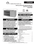
1
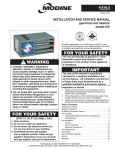
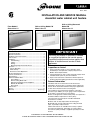
11-500.4 5H73211A1 Rev. C March, 2005 ® Floor Model C Sizes 2 thru 14 INSTALLATION AND SERVICE MANUAL steam/hot water cabinet unit heaters Wall or Ceiling Model CW Sizes 2 thru 14 Contents General Information ...............................................................1 Special Precautions ...............................................................2 SI (Metric) Conversion Factors ..............................................2 Unit Location..........................................................................2 Installation..............................................................................3 Unit Mounting ..................................................................3 Piping ..............................................................................3 Wiring ..............................................................................3 Mounting Height and Heater Throw ................................4 Operation ...............................................................................4 Prior to Operation ..............................................................4 Initial Start-up ....................................................................4 Automatic Control Operations ............................................4 Air Flow Arrangement ............................................................5 Controls and Features ...........................................................6 Specifications ........................................................................7 Dimensional/Motor Data ........................................................8 Floor Model C .................................................................8 Wall or Ceiling Model CW ...............................................9 Dimensional Data/Accessories/Options ........................10 Outside Air Wall Box .....................................................10 Duct Collars ..................................................................10 Maintenance ........................................................................11 Service ................................................................................11 Warranty ................................................................ Back Page Wall or Ceiling Recessed Model CW Sizes 2 thru 14 IMPORTANT The use of this manual is specifically intended for a qualified installation and service agency. A qualified installation and service agency must perform all installation and service of these appliances. Inspection on Arrival 1. Inspect unit upon arrival. In case of damage, report immediately to transportation company and your local Modine Sales Representative. 2. Check rating plate on unit to verify that power supply meets available electric power at point of installation. 3. Inspect unit received for conformance with description of product ordered (including specifications where applicable). General Information Installation and service instructions in this manual are applicable to the three types of steam/hot water cabinet unit heaters which should be installed in their proper applications for their most effective function as heating units. The condensers are warranted for operation at hot water pressures up to 200 lbs. per sq. in. gauge, and or temperatures up to 240°F or steam pressures up to 10psig. Motors are designed for continuous duty. They can operate in a maximum ambient temperature of 104°F (40°C). The unit heaters are listed by the Canadian Standards Association as certified. Model C units are fully exposed floor mounted types. Model CW units are fully exposed wall or ceiling mounted types, or partially of fully recessed. Cabinet unit heaters are available with a variety of options and control arrangements. Information on certain options and controls (when provided) is supplied separately from this manual. THIS MANUAL IS THE PROPERTY OF THE OWNER. PLEASE BE SURE TO LEAVE IT WITH THE OWNER WHEN YOU LEAVE THE JOB. SPECIAL PRECAUTIONS / SI (METRIC) CONVERSION FACTORS / UNIT LOCATION SPECIAL PRECAUTIONS THE INSTALLATION AND MAINTENANCE INSTRUCTIONS IN THIS MANUAL MUST BE FOLLOWED TO PROVIDE SAFE, EFFICIENT AND TROUBLE-FREE OPERATION. IN ADDITION, PARTICULAR CARE MUST BE EXERCISED REGARDING THE SPECIAL PRECAUTIONS LISTED BELOW. FAILURE TO PROPERLY ADDRESS THESE CRITICAL AREAS COULD RESULT IN PROPERTY DAMAGE OR LOSS, PERSONAL INJURY, OR DEATH. THESE INSTRUCTIONS ARE SUBJECT TO ANY MORE RESTRICTIVE LOCAL OR NATIONAL CODES. SI (METRIC) CONVERSION FACTORS Table 2.1 To Convert Multiply By To Obtain "W.C. (inches water column) 0.24 kPa psig 6.893 kpa °F (°F-32) × 0.555 °C inches 25.4 mm HAZARD INTENSITY LEVELS feet 0.305 1. DANGER: Indicates an imminently hazardous situation which, if not avoided, WILL result in death or serious injury. 2. WARNING: Indicates a potentially hazardous situation which, if not avoided, COULD result in death or serious injury. 3. CAUTION: Indicates a potentially hazardous situation which, if not avoided, MAY result in minor or moderate injury. 4. IMPORTANT: Indicates a situation which, if not avoided, MAY result in a potential safety concern. CFM 0.028 meters m3/min CFH btu/ft3 1.699 0.0374 m3/min mJ/m3 pound 0.453 kg btu/hr 0.000293 kW/hr gallons 3.785 liters DANGER Units must not be installed where they may be exposed to a potentially explosive or flammable atmosphere. WARNING 1. Disconnect power supply before making wiring connections to prevent electrical shock and equipment damage. 2. All appliances must be wired strictly in accordance with wiring diagram furnished with the appliance. Any wiring different from the wiring diagram could result in a hazard to persons and property. 3. Any original factory wiring that requires replacement must be replaced with wiring material having a temperature rating of at least 105°C. 4. When servicing or repairing this equipment, use only factory-approved service replacement parts. A complete replacement parts list may be obtained by contacting Modine Manufacturing Company. Refer to the rating plate on the appliance for complete appliance model number, serial number, and company address. Any substitution of parts or controls not approved by the factory will be at the owner’s risk. CAUTION 1. Do not reuse any electrical component which has been wet. Such component must be replaced. 2. Do not operate the units within steam pressure greater than 10 psig. Steam pressure must be 10 psig. or lower to avoid excessive discharge air temperatures that could cause burns or personal injury. 2 UNIT LOCATION DANGER Units must not be installed where they may be exposed to a potentially explosive or flammable atmosphere. 1. Units should not be installed in atmospheres where corrosive fumes or sprays are present. 2. Be sure no obstructions block air intake or air discharge of unit heater. 3. Columns, machinery, partitions, and other obstacles should not interfere with air streams from unit heaters. 4. Unit heaters installed in a building exposed to a prevailing wind should be located to direct a major volume of heated air along the windward wall of the building. 5. Vertical delivery unit heaters should generally be located in the central area of the space to be heated. Place horizontal delivery units along the walls of the same building where heat loss is usually greatest. 6. Arrange horizontal delivery units so they do not blow directly at occupants. 7. When only vertical delivery units are installed, they should be located so exposed walls are blanketed by their air streams. 8. Mounting height is critical for optimum performance. Refer to Mounting Height on page 4 before installation. IMPORTANT Start-up and adjustment procedures should be performed by a qualified service agency. INSTALLATION - UNIT MOUNTING / PIPING / ELECTRICAL CONNECTIONS INSTALLATION Unit Mounting CAUTION 1. Open front panel and line up end compartment with roughedin piping and position unit at ceiling or wall location. (Hinged cabinet doors may be removed to facilitate unit installation.) 2. Fasten floor or wall mounted unit to wall studs through the four mounting holes in the back of the unit. For ceiling mounted units sizes 2-6, suspend four 1/4" threaded hanger studs from ceiling joists to match mounting holes in back of unit and fasten with lockwashers and hex nuts. (For sizes 814, use a 3/8" threaded rod.) Perma-Lap® Frames A Perma-Lap® frame (see Figure 10.3 on page 10) provides a finished appearance to a recessed wall or ceiling cabinet unit heater. The installation is easy and assures a perfect fit by neatly framing the heater and covering any irregularities between the heater and the opening in the wall or ceiling. Because the bond between wall or ceiling surfaces and the Perma-Lap® framing is permanent, there is no opportunity for air leakage which can cause wall streaking. Since the enclosure front panel is never in contact with the wall or ceiling, servicing the heater involves simply removing the heater front panel and leaving the Perma-Lap® and cabinet enclosure permanently fixed in the recess opening. Perma-Lap® frames allow flexibility in recessing depth. Enclosures may be flush, recessed or partially recessed. Desired unit projection on partially recessed units is accomplished by positioning the unit within the Perma-Lap® frame. The four sided Perma-Lap® frame has a 3/8” projection and a 1 ½” width. Failure to wire this unit according to this wiring diagram may result in injury to the installer or user. For deviations, contact the factory. 1. 2. 3. 4. Piping CAUTION 1. Do not reuse any electrical component which has been wet. Such component must be replaced. 2. Do not operate the units within steam pressure greater than 10 psig. Steam pressure must be 10 psig. or lower to avoid excessive discharge air temperatures that could cause burns or personal injury. 1. On standard coil (single row), connections are 3/4" MPT on unit sizes 2 through 6. On high capacity coil (2 row), connections are 5/8" ID sweat on unit sizes 2 through 6. On unit sizes 8 through 14, either standard or high capacity coil, connections are 1" MPT. 2. Supply and return lines should be adequately sized to handle heating requirements under maximum load. 3. Attach air vent fitting at the high point of the piping in the unit on hot water systems. 4. Install piping to provide for expansion and contraction normally encountered with temperature changes. Electrical Connections WARNING 1. Disconnect power supply before making wiring connections to prevent electrical shock and equipment damage. 2. All appliances must be wired strictly in accordance with wiring diagram furnished with the appliance. Any wiring different from the wiring diagram could result in a hazard to persons and property. 3. Any original factory wiring that requires replacement must be replaced with wiring material having a temperature rating of at least 105°C. Installation of wiring must conform with local building codes, or in the absence of local codes, with the National Electric Code ANSI/NFPA 70 - Latest Edition. Unit must be electrically grounded in conformance to this code. In Canada, wiring must comply with CSA C22.1, Electrical Code. Electric wiring must be sized to carry the full load amp draw of the motor and any controls that are used with the unit heater. Overcurrent protectors should be sized based on motor current rating shown on the unit serial plate, and applicable national electric code procedures. All units are provided with an electrical junction box. Make wiring connections from 115V/60Hz/1Ø building service to control box as shown on wiring diagram furnished with the unit. Any damage to or failure of Modine units caused by incorrect wiring of the units is not covered by Modine’s standard warranty. Location of room thermostat, when supplied, should be in the natural circulating path of room air. Mount thermostat about five feet above floor level where it will not be affected by heat from the unit or other sources of drafts that would prevent it from properly controlling room temperature. See instructions packed with the thermostat. With ceiling mounted units, a multi-speed remote fan switch is supplied as standard. The switch can be recessed into a standard 2 x 4 electrical wall box. Figure 3.1 Standard Wiring Diagram for Cabinet Unit Heaters FUSED DISCONNECT SWITCH (BY OTHERS) 115V/60HZ/1Ø SUPPLY POWER L1 L2 GND THERMOSTAT (BY OTHERS) STANDARD SPEED CONTROL (ALL UNITS) BLOWER MOTOR BLOWER MOTOR GND WIRING LEGEND (2) MOTORS REQUIRED ON SIZES 8 THROUGH 14 FACTORY FIELD WIRE NUT LINE 3 INSTALLATION - MOUNTING HEIGHT / OPERATION Mounting Height Height at which cabinet unit heaters are installed is critical. Maximum mounting heights for all units are listed in the tables below. The data in tables are based on operating conditions of 2 lbs. steam or 220°F entering water with 60°F entering air. When operating conditions are other than those above, refer to chart for mounting height correction factor. To obtain the maximum mounting height at actual operating conditions, multiply the appropriate factor from chart by the mounting height in Tables. The mounting heights must be followed closely to assure maximum comfort. Strong opposing drafts, large obstructions in the air stream of the unit, and higher than normal discharge air temperatures (resulting from high steam pressures) can prevent the heated air discharged by the cabinet unit from reaching the floor. Under unfavorable conditions such as these, allowances must be made to assure maintenance of desired comfort. Table / Figure 4.1 Maximum Mounting Height Size H (Ft.) T (Ft.) 2 8 15 3 8 18 4 9 22 6 9 23 8 10 26 10 10 27 12 11 26 14 11 27 Size H (Ft.) T (Ft.) 2 7 8 3 8 10 4 8 11 6 8 12 8 10 16 10 10 18 12 11 20 14 11 21 H Intermittent Fan Operation — Hot Coil A room thermostat starts and stops the fan motor. An aquastat is sometimes strapped to the return piping to prevent fan operation when heat is not being supplied to the unit heater. T Inverted Air Flow Wall-Mounted Continuous Fan Operation — Intermittent Hot/Cold Coil A room thermostat controls a valve which opens to allow steam or hot water to supply the unit and closes to shut off the supply when the thermostat is satisfied. H T Standard Air Flow Ceiling-Mounted H T Inverted Air Flow Wall-Mounted T H CORRECTION FACTOR “R” 1.3 Steam Pressure 1.2 2 5 10 220° 230° 240° 1.1 1.0 .9 .8 .7 .6 170° 1. Set thermostat to lowest position. 2. Turn on power supply to unit. 3. Open return gate valve, and then open supply gate valve to unit. 4. Raise thermostat setting to desired position. 5. Adjust louvers (if provided) for desired heat distribution. 6. To insure proper sequence of operation, cycle unit on and off a few times by raising and lowering thermostat setting. 7. Check for proper rotation of fan. See dimensional drawings on page 8 or 9 for indication of fan rotation. Install one of the following operating systems for continuous automatic control. These correction factors are to be used as multipliers to correct the maximum recommended mounting heights “H” or heat throw “T” of cabinet unit heaters when operated with steam pressures other than 2 pounds or with water at other than entering temperature of 220°F. 160° Initial Start-Up Automatic Control Operations Table 4.3 Maximum Mounting Heights Correction Factors 4 1. Make sure fuses are installed in fused disconnect switches. 2. Check all electrical connections to assure they are secure. 3. Check rigidity of unit mounting. Tighten all fasteners, if necessary. 4. Inspect piping, strainers, traps, fittings, etc. Standard Air Flow Ceiling-Mounted Maximum mounting height and corresponding heat throw of heaters operating at standard conditions (2 lbs. steam or 220°F entering water, 60° entering air). .5 150° OPERATION 180° 190° 200° 210° AVERAGE WATER TEMP. (°F) INSTALLATION - AIR FLOW ARRANGEMENTS Figure 5.2 Inverted Air Flow Figure 5.1 Standard Air Flow Floor Mounted Floor Mounted Model C Arrangement 06 Model C Model C Arrangement 08 Arrangement 06 with Fresh Air Option (Refer to Option Descriptions) Wall Mounted Model CW Arrangement 00 Model CW Arrangement 06 Model CW Arrangement 96 Model C Arrangement 08 with Fresh Air Option (Refer to Option Descriptions) Model CW Arrangement 07 Model CW Arrangement 98 Wall Mounted Model CW Arrangement 08 Model CW Arrangement 90 Model CW Arrangement 97 Model CW Arrangement 96 Model CW Arrangement 98 Ceiling Mounted Model CW Arrangement 50 Model CW Arrangement 56 Model CW Arrangement 57 Model CW Arrangement 58 Recessed Floor➂ Recessed Floor➂ Model CW Arrangement 08 Recessed Wall➂ Recessed Ceiling➂ Model CW Arrangement 08 Model CW Arrangement 58 Figure 5.3 - Model Nomenclature Model Type C = Floor Unit CW = Exposed, Recessed or Ceiling Unit Arrangement 0 = Wall or Floor 5 = Ceiling 9 = Inverted Model CW Arrangement 98 CW 0 6 Recessed Wall➂ Model CW Arrangement 98 Perma-Lap® frame available for recessed units. Airflow Direction 0 = Bottom in, Top Out 6 = Front In, Top Out 7 = Bottom In, Front Out 8 = Front In, Front Out 5 CONTROLS AND FEATURES Figure 6.1 Controls and Features ➀ ➇ ➂ ➁ ➃ ➃ ➈ ➄ ➉ ➅ ➆ Product Features and Benefits Feature Benefits 1. One-Piece Cabinet Top and Sides 1. Cabinet top and sides are formed from a single sheet of 18 gauge steel reducing the number of parting lines common to multi-piece construction. Fronts are 16 gauge. All louvers are stamped as standard. 2. Wrap-Around Partitions and Back Sheet 2. Inner partition panels and back sheet are die-formed from a single sheet of 18 gauge steel. This assures precision fit and alignment of all internal components and maximum cabinet rigidity. 3. Cabinet unit heaters utilize five to eight structural components in the basic cabinet. The components are fixture-aligned and welded. 3 All-Welded Construction 4. Cabinet End Pockets 4. The two cabinet end pockets provide ample space for convenient installation of piping and electrical wiring. Easy access reduces costs and installation time. 5. Cabinet Finish 5. After assembly and welding operations are completed, the entire cabinet unit is treated for prevention of rust and corrosion. Entire cabinet is finished with a tan color, baked on enamel finish, which may be used as a final coat or repainted. 6. Quick-Change Permanent Filters 6. Filters are removable without tools. After opening the unit’s front panel, the filter easily slides out. Cleanable filters are provided as standard. 7. Insulation 7. Sound dampening insulation on all front panels. 8. Coils – Steam/Hot Water 8. All coils used in cabinet heaters use copper tube, aluminum fin construction with NPT connections; 3/4” for sizes 2 thru 6, and 1” for sizes 8 thru 14. Tubes are mechanically expanded into integral fin collars. Return bends and joints are silver alloy brazed and the coil is pressure-tested to 200 psi pressure. Field reversible coils allow piping to be made for left or right side connection, with left hand piping as factory standard. 9. Power Assembly 9. Blower platform, blower, and blower motor on all sizes are removable as a single unit. A direct drive, multi-speed, shaded pole motor with built in thermal overload protection powers the forward curved aluminum blower wheels. ;Right hand electrical as factory standard. 10. Speed Control 10. Solid state infinite speed control with off position. 11. Access Doors (not shown) 11. Tilt type access doors standard on model C units. 6 UNIT / MECHANICAL SPECIFICATIONS Table 7.1 Unit Data Specifications 2 3 4 6 8 10 12 14 1.0 1.1 1.3 1.5 1.6 1.8 2.3 2.7 3.4 3.6 3.4 3.6 4.6 4.8 4.6 4.8 3/4" NPT 5/8" ID Sweat 3/4" NPT 5/8" ID Sweat 3/4" NPT 5/8" ID Sweat 3/4" NPT 5/8" ID Sweat 1" NPT 1" NPT 1" NPT 1" NPT 1" NPT 1" NPT 1" NPT 1" NPT ▲ Unit Size Coil Standard – 1 Row Face Area, Ft.2 High Capacity – 2 Row Face Area, Ft.2 Standard Coil Connections . . . . . . . . . . . High Capacity Coil Connections . . . . . . . Blowers (Direct Drive) No./Dia. x Width (Inches) . . . . . . . . . . . . . 2 / 5-1/4 x 7 2 / 5-3/4 x 7 3 / 5-3/4 x 7 3 / 5-3/4 x 7 4 / 5-3/4 x 7 4 / 5-3/4 x 7 1050 625 1050 625 1050 625 1050 625 1050 625 1050 625 1050 625 1050 625 High CFM . . . . . . . . . . . . . . . . . . . . . . . . . Low CFM ① . . . . . . . . . . . . . . . . . . . . . . . 250 150 330 195 450 270 620 370 840 545 1050 685 1240 805 1430 930 1/30 115/1/60 1/30 115/1/60 1/20 115/1/60 1/20 115/1/60 1/30 1/20 115/1/60 1/30 1/20 115/1/60 1/20 115/1/60 1/20 115/1/60 Amps, Standard Shaded Pole Motors . . . Amps, Option #140 PSC Motor . . . . . . . . Amps, Option #141 High Static Motor . . . 1.7 .7 4.6 1.7 .7 4.6 2.37 1.05 4.6 2.37 1.05 4.6 4.07 1.75 9.2 4.07 1.75 9.2 4.74 2.10 9.2 4.74 2.10 9.2 Shipping Weight – Lbs. Model C . . . . . . . . . . . . . . . . . . . . . . . . . . Model CW . . . . . . . . . . . . . . . . . . . . . . . . 80 90 90 100 110 120 120 130 160 170 165 175 185 195 190 200 ② Motor HP . . . . . . . . . . . . . . . . . . . . . . . . . Volts/Phase/Hertz. . . . . . . . . . . . . . . . . . . ① ② 1 / 5-1/4 x 7 1 / 5-3/4 x 7 High Speed (Rpm) . . . . . . . . . . . . . . . . . . Low Speed (Rpm) ① . . . . . . . . . . . . . . . . Standard solid state speed control offers infinite speed control between high and low speed/CFM. Sizes 2-6 have one motor. Sizes 8-14 have two motors. Unit Mechanical Specifications Cabinet Floor models shall be provided with stamped louvers and a one inch high dust barrier at the bottom. The cabinet shall be 18-gauge steel with 16 gauge front panels. All painted surfaces shall be treated for corrosion resistance prior to being finished with a tan, baked on enamel finish, which may be used as a final coat or repainted. All unpainted steel shall be galvanized. (When specified) color as selected by architect shall be provided in one of 9 optional colors as shown on manufacturer’s color chart 11-405. Wall or ceiling models shall have cabinets with stamped louvers. The entire bottom of the unit must be enclosed. Access to the speed control shall be through the easy access 16-gauge front panels. (Available, when specified, as optional equipment) an access door shall be provided for speed control access. All models shall have two 9" minimum wide piping end pockets. All wall and ceiling units shall have safety hinged access panels that can be easily removed during installation. Coils The heating coils shall provide specified capacities and not exceed the pressure drop and GPM listed in this catalog. Coils shall be suitable for 200 PSI working pressure with 240°F water. Steam pressure shall not exceed 10 psi. Motor Speed Control The unit shall have a unit-mounted solid state motor speed control, with high through low speeds and off positions on all models. When dampers are specified, indicate one of the following: 1. These dampers shall be controlled from the end pocket with a manual control assembly that indicates the open and closed positions. 2. The damper shall be controlled by an electric, spring-return type motor, which will be energized when the blower motor is turned on thus moving the damper to the 25% or 100% position. It will be de-energized and close the damper when the blower motor is off. Motors, Blowers and Drives Blowers shall be of the centrifugal, forward curved type, to provide even air distribution and low sound level. All units shall have shaded pole (permanent split capacitor available when specified as optional equipment) direct-drive motors. The motor and blower assembly shall be capable of being easily removed from the unit. Motors are built for continuous duty to NEMA standards. Grilles (optional equipment) When specified, aluminum linear bar inlet and/or outlet grilles shall be provided. When specified, outlet grilles may have two-way deflection louvers. Filters All air, both fresh and return, shall be filtered by a cleanable expanded aluminum filter. Dampers (optional equipment) When specified, the unit shall be equipped with a 25% galvanized steel fresh air blade damper. Model C, floor units only. 7 DIMENSIONAL / MOTOR DATA Floor Mounted Figure 8.1 Floor Model C, Sizes 2-14 Steam/Hot Water Cabinet Unit Heaters ACCESS DOOR ACCESS DOOR 43/4" C F COIL CONNECTIONS 3 SIZES 2-6: /4" NPT FOR STANDARD COIL 5 /8" I.D. SWEAT FOR TWO ROW COIL SIZES 8-14: 1" NPT, ONE OR TWO ROW COIL 51/2" G SPEED CONTROL AND J-BOX L N /16" MOUNTING HOLES SIZES 8-14 ONLY 7 J /2" 1 (size 8-14 only) 3" Optional Outlet 11" 41/2" SPEED CONTROL AND J-BOX 23/4" K B SIZES 2-6 45/8" X 3/8" SLOTTED MOUNTING HOLES IN REAR FLANGE 41/2" M E AIR INLET FILTER H D A NOTE: Left hand piping is standard, right hand piping available when specified. Bottoms of end compartments are open for piping and electrical access. Table 8.1 Cabinet Dimensions (inches) Table 8.2 Filter Dimensions (inches) ➀ Unit Size A B C D E F G H J 2 3 4 6 8 10 12 14 38-3/4 43-3/4 48-3/4 61-3/4 71-3/4 71-3/4 83-3/4 83-3/4 25 25 25 25 28 28 28 28 9-3/4 9-3/4 9-3/4 9-3/4 12 12 12 12 8 8 8 8 10 10 10 10 5 5 5 5 7 7 7 7 5-1/8 5-1/8 5-1/8 5-1/8 5-1/8 5-7/8 5-1/8 5-7/8 15-5/8 19-5/8 27-5/8 39-5/8 47-5/8 47-5/8 59-5/8 59-5/8 19-5/8 23-5/8 27-5/8 39-5/8 30-5/8 39-5/8 51-5/8 51-5/8 – – – – 9-3/4 9-3/4 9-3/4 9-3/4 Table 8.3 Coil Connection Dimensions (inches) Unit Size 2 thru 6 K L M N 22-1/2 7-3/8 15-1/4 2-3/8 8 thru 14 25-5/8 9-1/4 18 1-5/8 80 90 110 120 160 165 185 190 Unit Size 2 ................ 8-1/2 3 ................ 8-1/2 4 ................ 8-1/2 6 ................ 8-1/2 8 & 10 ............ 10-3/4 12 & 14 ........... 10-3/4 ➀ x x x x x x 20-3/4 25-3/4 30-3/4 43-3/4 49-3/4 61-3/4 x x x x x x 1/2 1/2 1/2 1/2 1/2 1/2 Filters are permanent/cleanable. Table 8.4 Motor Ratings (115 volts/60hz/1Ø) Unit size 2+3 4+6 8 + 10 12 + 14 8 Approx. Shipping Weight lbs. Motor qty. 1 1 1 1 2 Standard Motor HP Total Amps 1/30 1.7 1/20 2.37 1/30 4.07 1/20 1/20 4.74 PSC Motor Option 140 HP Total Amps 1/30 0.70 1/20 1.05 1/30 1.75 1/20 1/20 2.10 High Static Motor option 141 HP Total Amps 0.4 4.60 0.4 4.60 0.8 9.20 0.8 0.8 9.20 DIMENSIONAL / MOTOR DATA Exposed or Recessed Wall / Ceiling Mounted Figure 9.1 Wall or Ceiling Model CW, Sizes 2-14 Steam/Hot Water Cabinet Unit Heaters L C F COIL CONNECTIONS 3 SIZES 2-6: /4" NPT FOR STANDARD COIL 5 /8" I.D. SWEAT FOR TWO ROW COIL SIZES 8-14: 1" NPT, ONE OR TWO ROW COIL G Standard Outlet N 7 /16" MOUNTING HOLES MODEL SIZES 8-14 ONLY J (size 8-14 only) /2" 1 3" Optional Outlet 41/4" SPEED CONTROL AND J-BOX K 11" B 93/4" M Optional Inlet SIZES 2-6 45/8" X 3/8" SLOTTED MOUNTING HOLES IN REAR FLANGE 41/4" 23/4" Standard Inlet A NOTE: Left hand piping is standard, right hand piping available when specified. Bottoms of end compartments are open for piping and electrical access. Table 9.1 Cabinet Dimensions (inches) Unit Size 2 3 4 6 8 10 12 14 Table 9.2 Filter Dimensions (inches) ➀ A B C F G J 38-3/4 43-3/4 48-3/4 61-3/4 71-3/4 71-3/4 83-3/4 83-3/4 25 25 25 25 28 28 28 28 9-3/4 9-3/4 9-3/4 9-3/4 12 12 12 12 5-1/8 5-1/8 5-1/8 5-1/8 5-1/8 5-7/8 5-1/8 5-7/8 15-5/8 19-5/8 27-5/8 39-5/8 47-5/8 47-5/8 59-5/8 59-5/8 – – – – 9-3/4 9-3/4 9-3/4 9-3/4 Table 9.3 Coil Connection Dimensions (inches) Unit Size 2 thru 6 K L M N 22-1/2 7-3/8 15-1/4 2-3/8 8 thru 14 25-5/8 9-1/4 18 1-5/8 Approx. Shipping Weight lbs. 90 100 120 130 170 175 195 200 Unit Size 2 .................... 3 .................... 4 .................... 6 .................... 8-1/2 8-1/2 8-1/2 8-1/2 x x x x 20-3/4 25-3/4 30-3/4 43-3/4 x x x x 1/2 1/2 1/2 1/2 8 & 10 ................ 10-3/4 12 & 14 ............... 10-3/4 x x 49-3/4 61-3/4 x x 1/2 1/2 ➀ Filters are permanent/cleanable. Table 9.4 Motor Ratings (115 volts/60hz/1Ø) Unit size 2+3 4+6 8 + 10 12 + 14 Motor qty. 1 1 1 1 2 Standard Motor HP Total Amps 1/30 1.7 1/20 2.37 1/30 4.07 1/20 1/20 4.74 PSC Motor Option 140 HP Total Amps 1/30 0.70 1/20 1.05 1/30 1.75 1/20 1/20 2.10 High Static Motor option 141 HP Total Amps 0.4 4.60 0.4 4.60 0.8 9.20 0.8 0.8 9.20 9 DIMENSIONAL DATA - ACCESSORIES / OPTIONS Figure 10.1 Model CW - Duct Collars C Table 10.1 ➀ ➁ Options 122 and 123 - Model CW 100% Air Inlet or Outlet Duct Collars A C D B E Unit 3/4" 3/4" A C B C Size 2 A 18-1/4 B 4-1/4 C 10-3/8 D 2-1/2 E 3 3 4 23-1/4 28-1/4 4-1/4 4-1/4 10-3/8 10-3/8 2-1/2 2-1/2 3 3 6 41-1/4 4-1/4 10-3/8 2-1/2 3 8 44-1/4 4-1/4 10-7/8 2-1/2 5-1/4 10 44-1/4 5-1/4 10-7/8 2-1/2 4-1/4 12 58-1/4 4-1/4 12-7/8 2-1/2 5-1/4 14 58-1/4 5-1/4 12-7/8 2-1/2 4-1/4 E Table 10.2 ➀ ➁ Options 124, 125, 134, 135 and 137 - Model C 25% and 100% Fresh Air Duct Collar Figure 10.2 Model C - Outside Air Duct Collar Outside Air Percentage 25% 100% Options 124, 134 and 137 Options 125 and 135 Unit Size A B C A B C 2 12 1/4 3 1/2 13 1/4 18 1/2 4 1/4 10 1/8 3 12 1/4 3 1/2 15 3/4 23 1/2 4 1/4 10 1/8 4 12 1/4 3 1/2 18 1/4 28 1/2 4 1/4 10 1/8 6 12 1/4 3 1/2 24 3/4 41 1/2 4 1/4 10 1/8 8 10 24 1/4 24 1/4 3 1/2 3 1/2 23 3/4 23 3/4 44 1/2 44 1/2 4 1/4 5 1/4 13 5/8 13 5/8 12 24 1/4 3 1/2 29 3/4 58 1/2 4 1/4 12 5/8 14 24 1/4 3 1/2 29 3/4 58 1/2 5 1/4 12 5/8 3/4" B C A Figure 10.3 Model CW - Permalap Frame 10 C ➀ ➁ All dimensions are in inches. Includes 3/4" top and bottom duct flanges for duct connection. MAINTENANCE / SERVICE All heating equipment should be serviced before each heating season to assure proper operations. The following items may be required to have more frequent service scheduled based on the environment in which the unit is installed, and the frequency of the equipment operation. Motors A. Cleaning Remove grease and dirt on motor during each inspection or lubrication. Open frame motors should be blown clean every heating season, or whenever coils are cleaned, whichever is sooner. B. Lubrication 1. Lubricate motor according to manufacturer’s instructions located on the motor. 2. When no motor oiling instructions are on the motor, oil the motor every two thousand hours of operation with SAE20 non-detergent motor oil for units in normal applications. Adjust oiling according to usage and atmosphere. 3. Some motors do not have oil fittings. These motors are lubricated for long life and do not require further lubrication. 4. Check motor shaft for excessive end play every 3 to 5 years. C. Overload Protection A change in line voltage higher or lower than motor nameplate rating may cause overheating and serious motor damage. Check plant voltage conditions. A separate manual starter with thermal overload protection device is recommended for those units that do not have motors with built-in overload protection. B. Internal Corrosion Safeguards 1. Provide controlled water treatment — don’t use excess of boiler compounds. Contact your boiler compound supplier for proper usage or the services of a water treatment laboratory. 2. Periodic internal flushing of the coils is recommended in areas where water supply is suspected of causing scale. Use an alkaline-chelant solution and introduce it at the main pump of the hydronic system. Flush thoroughly. WARNING Using inorganic or mineral acids, such as muriatic (hydrochloric) acid, even though inhibited, may lead to severe damage including corrosion and leakage. 3. De-aerate boiler feed-water (particularly if large amount of new water is used). 4. Insure rapid continuous and adequate condensate drainage by properly sized and installed traps and piping. Check traps for sticking. Clean strainers ahead of traps. (When traps don’t work, condensate accumulates in unit heater coil; water hammer results.) 5. Adequately vent each unit. 6. Use low pressure steam when possible. Casings A. Cleaning 1. Periodic cleaning of casings is recommended to remove dirt, grease and corrosive substances that may injure finish. Rusted or corroded spots should be cleaned and repainted. 2. Clean air filters every three months or sooner depending on dust conditions. Coils B. General Inspection A. Cleaning Tighten fan guard and motor bracket. Check fan for proper clearance, free rotation and firm connection to shaft. When servicing is complete, tag unit to indicate date of inspection, lubrication and cleaning. Clean coil at least once a year; more often under unfavorable conditions. Unless coil is kept reasonably free of dirt, lint and grease, its original heating capacity will be reduced — possibly to a serious degree, and motor damage may result. Two commonly used cleaning methods are: 1. Loosen dirt by brushing fins with a soft brush on side where air enters coil and then turn on fan to blow dirt from unit. 2. Use high pressure air hose to loosen dirt by blowing from side where air leaves coil (side adjacent to louvers on blowthrough units; side adjacent to fan on draw-through units). Coils subjected to corrosive fumes should be checked and cleaned frequently. Do not use any commercial solvent that could deteriate the coil and do not use any liquid or steam sprays that could damage electrical components. Good filter maintenance will minimize the frequency of coil cleaning. SERVICE If a qualified service person cannot solve the problem, consult your local plumbing/electrical contractor or local Modine representative. When servicing, repairing or replacing parts on these units always give the complete Model Number and Serial Number from the unit identification plate. Replacement Parts When requesting parts please contact your local representative. Please have full model and serial number available. 11 WARRANTY Seller warrants its products to be free from defects in material and workmanship, EXCLUSIVE, HOWEVER, of failures attributable to the use of materials substituted under emergency conditions for materials normally employed. This warranty covers replacement of any parts furnished from the factory of Seller, but does not cover labor of any kind and materials not furnished by Seller, or any charges for any such labor or materials, whether such labor, materials or charges thereon are due to replacement of parts, adjustments, repairs, or any other work done. This warranty does not apply to any equipment which shall have been repaired or altered outside the factory of Seller in any way so as, in the judgment of Seller, to affect its stability, nor which has been subjected to misuse, negligence, or operating conditions in excess of those for which such equipment was designed. This warranty does not cover the effects of physical or chemical properties of water or steam or other liquids or gases used in the equipment. BUYER AGREES THAT SELLER’S WARRANTY OF ITS PRODUCTS TO BE FREE FROM DEFECT IN MATERIAL AND WORKMANSHIP, AS LIMITED HEREIN, SHALL BE IN LIEU OF AND EXCLUSIVE OF ALL OTHER WARRANTIES, EITHER EXPRESS OR IMPLIED, WHETHER ARISING FROM LAW, COURSE OF DEALING, USAGE OF TRADE, OR OTHERWISE, THERE ARE NO OTHER WARRANTIES, INCLUDING WARRANTY OF MERCHANTABILITY OR FITNESS FOR PURPOSE, WHICH EXTEND BEYOND THE PRODUCT DESCRIPTION CONFIRMED BY BUYER AND SELLER AS OF THE DATE OF FINAL AGREEMENT. This warranty is void if the input to the product exceeds the rated input as indicated on the product serial plate by more than 5% on gas-fired and oil-fired units, or if the product in the judgment of SELLER has been installed in a corrosive atmosphere, or subjected to corrosive fluids or gases, been subjected to misuse, negligence, accident, excessive thermal shock, excessive humidity, physical damage, impact, abrasion, unauthorized alterations, or operation contrary to SELLER’S printed instructions, or if the serial number has been altered, defaced or removed. Heat Exchangers For Seller’s non-separated combustion Gas-Fired Unit Heaters BUYER’S REMEDY FOR BREACH OF WARRANTY, EXCLUSIVE OF ALL OTHER REMEDIES PROVIDED BY LAW, IS LIMITED TO REPAIR OR REPLACEMENT AT THE FACTORY OF SELLER, ANY HEAT EXCHANGER WHICH SHALL, WITHIN TEN YEARS FROM DATE OF FIRST BENEFICIAL USE BY BUYER OR ANY OTHER USER, WITHIN TEN YEARS FROM DATE OF RESALE BY BUYER OR ANY OTHER USER, WITHIN TEN YEARS FROM DATE OF RESALE BY BUYER IN ANY UNCHANGED CONDITION, OR WITHIN ONE HUNDRED TWENTY-SIX MONTHS FROM DATE OF SHIPMENT FROM SELLER, WHICHEVER OCCURS FIRST, BE RETURNED TO SELLER WITH TRANSPORTATION CHARGES PREPAID AND WHICH THE EXAMINATION OF SELLER SHALL DISCLOSE TO HAVE BEEN DEFECTIVE; EXCEPT THAT WHEN THE PRODUCT IS TO BE USED BY BUYER AS A COMPONENT PART OF EQUIPMENT MANUFACTURED BY BUYER, BUYER’S REMEDY FOR BREACH, AS LIMITED HEREIN, SHALL BE LIMITED TO ONE YEAR FROM DATE OF SHIPMENT FROM SELLER. FOR GAS-FIRED PRODUCTS INSTALLED IN HIGH HUMIDITY APPLICATIONS AND UTILIZING STAINLESS STEEL HEAT EXCHANGERS, BUYER’S REMEDY FOR BREACH, AS LIMITED HEREIN, SHALL BE LIMITED TO TEN YEARS FROM DATE OF SHIPMENT FROM SELLER. For Seller's Low Intensity Gas-Fired Infrared Heaters BUYER'S REMEDY FOR BREACH OF WARRANTY, EXCLUSIVE OF ALL OTHER REMEDIES PROVIDED BY LAW, IS LIMITED TO REPAIR OR REPLACEMENT AT THE FACTORY OF SELLER, ANY HEAT EXCHANGER WHICH SHALL, WITHIN FIVE YEARS FROM DATE OF FIRST BENEFICIAL USE BY BUYER OR ANY OTHER USER, WITHIN FIVE YEARS FROM DATE OF RESALE BY BUYER OR ANY OTHER USER, WITHIN FIVE YEARS FROM DATE OF RESALE BY BUYER IN ANY UNCHANGED CONDITION, OR WITHIN 66 MONTHS FROM DATE OF SHIPMENT FROM SELLER, WHICHEVER OCCURS FIRST, BE RETURNED TO SELLER WITH TRANSPORTATION CHARGES PREPAID AND WHICH THE EXAMINATION OF SELLER SHALL DISCLOSE TO HAVE BEEN DEFECTIVE; EXCEPT THAT WHEN THE PRODUCT IS TO BE USED BY BUYER AS A COMPONENT PART OF EQUIPMENT MANUFACTURED BY BUYER, BUYER'S REMEDY FOR BREACH, AS LIMITED HEREIN, SHALL BE LIMITED TO ONE YEAR FROM DATE OF SHIPMENT FROM SELLER. Heat Exchanger (Condensers) for all Seller’s products except nonseparated combustion Gas-Fired Unit Heaters and Infrared Heaters, all Burners except Infrared Heaters, and Sheet Metal for all Seller's products BUYER’S REMEDY FOR BREACH OF WARRANTY, EXCLUSIVE OF ALL OTHER REMEDIES PROVIDED BY LAW, IS LIMITED TO REPAIR OR REPLACEMENT AT THE FACTORY OF SELLER, ANY HEAT EXCHANGER (CONDENSER) OR BURNER WHICH SHALL, WITHIN ONE YEAR FROM DATE OF FIRST BENEFICIAL USE BY BUYER OR ANY OTHER USER, WITHIN ONE YEAR FROM DATE OF RESALE BY BUYER IN ANY UNCHANGED CONDITION, OR WITHIN EIGHTEEN MONTHS FROM DATE OF SHIPMENT FROM SELLER, WHICHEVER OCCURS FIRST, BE RETURNED TO SELLER WITH TRANSPORTATION CHARGES PREPAID AND WHICH THE EXAMINATION OF SELLER SHALL DISCLOSE TO HAVE BEEN DEFECTIVE; EXCEPT THAT WHEN THE PRODUCT IS TO BE USED BY BUYER AS A COMPONENT PART OF EQUIPMENT MANUFACTURED BY BUYER, BUYER’S REMEDY FOR BREACH, AS LIMITED HEREIN, SHALL BE LIMITED TO ONE YEAR FROM DATE OF SHIPMENT FROM SELLER. Burners For Seller's Low Intensity Gas-Fired Infrared Heaters BUYER'S REMEDY FOR BREACH OF WARRANTY, EXCLUSIVE OF ALL OTHER REMEDIES PROVIDED BY LAW, IS LIMITED TO REPAIR OR REPLACEMENT AT THE FACTORY OF SELLER, ANY BURNER WHICH SHALL, WITHIN TWO YEARS FROM DATE OF FIRST BENEFICIAL USE BY BUYER OR ANY OTHER USER, WITHIN TWO YEARS FROM DATE OF RESALE BY BUYER IN ANY UNCHANGED CONDITION, OR WITHIN 30 MONTHS FROM DATE OF SHIPMENT FROM SELLER, WHICHEVER OCCURS FIRST, BE RETURNED TO SELLER WITH TRANSPORTATION CHARGES PREPAID AND WHICH THE EXAMINATION OF SELLER SHALL DISCLOSE TO HAVE BEEN DEFECTIVE; EXCEPT THAT WHEN THE PRODUCT IS TO BE USED BY BUYER AS A COMPONENT PART OF EQUIPMENT MANUFACTURED BY BUYER, BUYER'S REMEDY FOR BREACH, AS LIMITED HEREIN, SHALL BE LIMITED TO ONE YEAR FROM DATE OF SHIPMENT FROM SELLER. For Seller's High Intensity Gas-Fired Infrared Heaters BUYER'S REMEDY FOR BREACH OF WARRANTY, EXCLUSIVE OF ALL OTHER REMEDIES PROVIDED BY LAW, IS LIMITED TO REPAIR OR REPLACEMENT AT THE FACTORY OF SELLER, ANY BURNER WHICH SHALL, WITHIN TEN YEARS FROM DATE OF FIRST BENEFICIAL USE BY BUYER OR ANY OTHER USER, WITHIN TEN YEARS FROM DATE OF RESALE BY BUYER IN ANY UNCHANGED CONDITION, OR WITHIN 126 MONTHS FROM DATE OF SHIPMENT FROM SELLER, WHICHEVER OCCURS FIRST, BE RETURNED TO SELLER WITH TRANSPORTATION CHARGES PREPAID AND WHICH THE EXAMINATION OF SELLER SHALL DISCLOSE TO HAVE BEEN DEFECTIVE; EXCEPT THAT WHEN THE PRODUCT IS TO BE USED BY BUYER AS A COMPONENT PART OF EQUIPMENT MANUFACTURED BY BUYER, BUYER'S REMEDY FOR BREACH, AS LIMITED HEREIN, SHALL BE LIMITED TO ONE YEAR FROM DATE OF SHIPMENT FROM SELLER. All Other Components Excluding Heat Exchanger (Condenser), Burner, and Sheet Metal For all Seller's products except Direct-Fired Heaters and High Intensity Gas-Fired Infrared Heaters BUYER’S REMEDY FOR BREACH OF WARRANTY, EXCLUSIVE OF ALL OTHER REMEDIES PROVIDED BY LAW, IS LIMITED TO REPAIR OR REPLACEMENT AT THE FACTORY OF SELLER, ANY PART OR PARTS WHICH SHALL, WITHIN TWO YEARS FROM DATE OF FIRST BENEFICIAL USE BY BUYER OR ANY OTHER USER, WITHIN TWO YEARS FROM DATE OF RESALE BY BUYER IN ANY UNCHANGED CONDITION, OR WITHIN THIRTY MONTHS FROM DATE OF SHIPMENT FROM SELLER, WHICHEVER OCCURS FIRST, BE RETURNED TO SELLER WITH TRANSPORTATION CHARGES PREPAID AND WHICH THE EXAMINATION OF SELLER SHALL DISCLOSE TO HAVE BEEN DEFECTIVE; EXCEPT THAT WHEN THE PRODUCT IS TO BE USED BY BUYER AS A COMPONENT PART OF EQUIPMENT MANUFACTURED BY BUYER, BUYER’S REMEDY FOR BREACH, AS LIMITED HEREIN, SHALL BE LIMITED TO ONE YEAR FROM DATE OF SHIPMENT FROM SELLER. For Seller's Direct-Fired Heaters and High Intensity Gas-Fired Infrared Heaters BUYER’S REMEDY FOR BREACH OF WARRANTY EXCLUSIVE OF ALL OTHER REMEDIES PROVIDED BY LAW IS LIMITED TO REPAIR OR REPLACEMENT AT THE SELLER’S OPTION ANY PART OR PARTS WHICH SHALL WITHIN A PERIOD OF ONE YEAR FROM DATE OF FIRST BENEFICIAL USE BY BUYER OR ANY OTHER USER, WITHIN ONE YEAR FROM DATE OF RESALE BY BUYER IN ANY UNCHANGED CONDITION, OR WITHIN 18 MONTHS FROM DATE OF SHIPMENT FROM SELLER, WHICHEVER OCCURS FIRST, BE RETURNED TO SELLER WITH TRANSPORTATION CHARGES PREPAID AND WHICH THE EXAMINATION OF THE SELLER SHALL DISCLOSE TO HAVE BEEN DEFECTIVE. BUYER AGREES THAT IN NO EVENT WILL SELLER BE LIABLE FOR COSTS OF PROCESSING, LOST PROFITS, INJURY TO GOODWILL, OR ANY OTHER CONSEQUENTIAL OR INCIDENTAL DAMAGES OF ANY KIND RESULTING FROM THE ORDER OR USE OF ITS PRODUCT, WHETHER ARISING FROM BREACH OF WARRANTY, NONCONFORMITY TO ORDERED SPECIFICATIONS, DELAY IN DELIVERY, OR ANY LOSS SUSTAINED BY THE BUYER. Modine Manufacturing Company has a continuous product improvement program; it reserves the right to change design and specifications without notice. Commercial HVAC&R Division 604 Liberty Lane West Kingston, RI 02892 Phone: 1.800.828.4328 www.modine.com © Modine Manufacturing Company 2005 3/05 - 2.5M Litho in USA