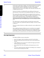
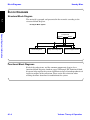
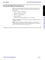
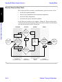
1
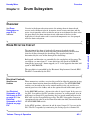
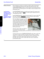
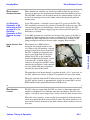
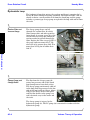
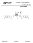
Housby Mixer
Chapter 1:
How the Machine is Used
General System Information
A1
A
HOW THE MACHINE IS USED
Most of the controls are electrically operated through the PLC
(Programmable Logic Controller) inside the cab. The driver operates these
controls through switches in the cab or at the rear of the machine.
The drum is supported and rotated by a motor and gearbox at the front
pedestal and supported by two rollers at the rear pedestal. Gravity holds the
drum in place, but the drum can lift free of the rollers a small distance and
drop back onto them. Flat spots can develop on the rollers and drum as the
result of a stationary drum bouncing as the truck travels. To prevent this,
the driver always has the drum rotating when the truck is moving.
The drum is rotated at approximately 20 rpm while mixing, then slowed to 1
rpm while enroute to and from the job site. To discharge the concrete,
rotation is reversed and the drum is turned at whatever rate is needed to
supply concrete down the chute to the contractor.
To properly mix the concrete, the driver rotates the drum a certain number
to times. A drum rotation counter on the control panel counts and displays
the number of revolutions.
The flighting or fins welded into the drum roll and mix the material as the
drum rotates. To discharge the mix, the driver reverses the direction of the
drum rotation. The flighting is shaped to auger the mix up and out of the
drum opening when the drum rolls in reverse.
The driver raises the bridge axle for all activities except travelling on paved
roads. When loaded with five or more yards of concrete, the bridge axle is
lowered (on paved roads) to spread the weight, dramatically reducing road
wear and allowing heavier legal payloads. The wheels of the bridge axle
caster to allow easier steering. Since they would hinder steering in reverse,
the bridge axle automatically raises when the driver shifts the truck into
reverse.
When loaded, the driver physically adjusts a knob controlling a pressure
reducing valve to set the downforce of the bridge axle for the weight of the
load.
Continued on next page...
Volume- Theory of Operation
A1-1
General System Information
The B-1 Mixer is used to mix and deliver concrete to job sites.
System Overview
Housby Mixer
A1
1
At the top rear of the drum, a hopper can be lowered to direct dry materials
into the drum when loading. The hopper is raised to allow a larger exit
opening when the concrete is discharged at the job site. The hopper
automatically lowers whenever the bridge axle is lowered or when the truck
is shifted into reverse gear.
At the site, the driver can hydraulically raise and lower the chute and
physically move it from side to side, provided the bridge axle is fully raised.
General System Information
The strength and quality of finished concrete depends heavily on how wet
the mix is when it is poured. The wetness or “slump” is measured by a slump
meter (actually a pressure gauge). (The slump meter is optional.) It
measures the amount of resistance to drum rotation caused by the mix
riding up the drum walls on the flighting. A wet mix pours off of the flighting
while a drier mix clings to the flighting longer as it is carried up the drum
wall.
The slump meter has moveable markers attached to the exterior of the
gauge face which can be positioned to indicated “slumps” of 1 inch, 2 inches,
3 inches, etc.
If the mix is too dry, the driver can add water from the water tank directly to
the drum.
After completing the pour, the driver can use a water hose (one at ground
level and another at the top of the ladder) to wash wet concrete off of the
truck before it hardens. Usually, the remaining water is added to the empty
drum to slosh out the drum interior as the truck travels back to the plant.
SYSTEM OVERVIEW
The Housby B1 Mixer system is designed to:
A1-2
•
operate the hopper, used for loading dry materials in to the drum
•
rotate the drum to mix dry materials with water and to discharge the
concrete
•
supply additional water to the mix, if needed, and supply pressurized
water for after-pour wash-down.
•
raise and lower the chute used to deliver discharged concrete to the
forms
•
raise, lower and provide proper downforce to the bridge axle, to allow the
truck to legally transport greater loads.
Volume- Theory of Operation
Housby Mixer
Subsystems Overview
SUBSYSTEMS OVERVIEW
These rotate the hopper to the charging and discharging positions, and raise
and lower the chute, and lock/unlock the chute pivot (to allow it to swing
right and left).
A1
Hopper and Chute Circuits
This rotates the drum at variable speeds in charge direction to mix
materials, and in discharge direction to force the mix out of the drum and
into the chute. When not mixing or discharging, a 1 RPM setting turns the
drum slowly to prevent the concrete from hardening or prevent the truck’s
bouncing from pounding flat spots in the drum.
The drum subsystem also includes the water tank used to add water to the
mix.
Bridge Axle Subsystem
This raises and lowers the bridge axle and provides proper downforce on the
bridge axle to spread vehicle and load weight while in transit on hard
surfaced roads.
Common Components
In addition to these three subsystems, the system also includes components
common to two or more subsystems. The system is divided this way to allow
easier discussion and troubleshooting of the system.
Volume- Theory of Operation
A1-3
General System Information
Drum Subsystem
Block Diagrams
Housby Mixer
Bl
BLOCK DIAGRAMS
Structural Block Diagram
A1
1
The material is grouped and presented in the manuals according to the
structural block diagram.
Housby B1 Mixer System
General System Information
Common
Components
Electric
Hydraulic
Ch 2
Drum Subsystem
Ch 3
Bridge Axle Subsystem
Chute & Hopper Circuits
Ch 4
Ch 5
Functional Block Diagrams
Each of the subsystems, and the common components chapter, has a
functional block diagram, found on pages XX through XX. Functional block
diagrams help explain the system and illustrate logical interdependencies of
inputs to outputs of the subsystem. These assist the technician when
making decisions about how to troubleshoot the system.
A1-4
Volume- Theory of Operation
Housby Mixer
Housby B1 Mixer System Service
•
Volume A—Theory of Operation
•
Volume B—Performance Checks
•
Volume C—Troubleshooting
•
Volume D—Repair
•
Volume E—Schematics and Diagrams (11 x 17″ format)
A glossary of abbreviations and terms and an index are provided at the back
of the Repair volume.
NOTE: This manual does not cover the truck chassis, engine or items
related to the chassis or engine. Consult the appropriate manuals from the
chassis and engine manufacturer when necessary.
Volume- Theory of Operation
A1-5
General System Information
This manual is designed to help the technician repair a faulty system and
return it to service as quickly as possible. The manual is divided into five
main sections:
A1
HOUSBY B1 MIXER SYSTEM SERVICE
Housby B1 Mixer System Service
Housby Mixer
Service Process Flow Chart
The tasks involved in returning a malfunctioning system to service are to:
A1
1
•
localize the reported problem
•
isolate faulty components from functioning components
•
repair the faulty components
•
verify that the repairs solved the problem
General System Information
As this flow chart indicates, this volume—Volume A - Theory of Operation—
is not critical to the repair process. The intent of this volume is to familiarize
you with the machine and its subsystems.
LOCALIZE
ISOLATE
Troubleshoot faulty
subsystem
REPAIR
VERIFY
Problem
found
Only 1 subsystem
fails PC
Reported
Problem
Conduct
Performance
Checks for all
subsystems
Problem
not found
Repair
as
directed
Repeat
Performance
Checks for
repaired
subsystem
Return
system to
Pass PC service
Fail PC
More than 1
subsystem fails PC
Troubleshoot Common
Components
Volume B
Performance Checks
A1-6
Volume C
Troubleshooting
Volume D
Repair
Volume B
Performance Checks
Volume- Theory of Operation
Housby Mixer
About This Manual
ABOUT THIS MANUAL
upon machine knowledge and configuration at the time the manual was
written. Due to ongoing efforts to continuously improve the equipment,
there may be changes on the machine not reflected in this manual.
A1
NOTE: This manual provides information and service procedures based
General System Information
Procedures given in this manual provide one method for completing a given
task. Additional information may be available through HOUSBY Service
Support resources.
Organization of Material
Volumes A, B, C and D of this manual are divided into chapters for:
•
Safety and General Information (Chapter 1)
•
Common Components of the other subsystems (Chapter 2)
•
Drum subsystem (Chapter 3)
•
Bridge Axle subsystem (Chapter 4)
•
Chute and Hopper circuits (Chapter 5)
Chapters are added to cover ancillary items:
•
Engine Speed Control (Chapter 6)
•
Work Lights (Chapter 7)
Volume E is large format pages showing schematics functional diagrams and
harness diagrams.
Currency of Material
The instructions, illustrations and specifications in this manual are based
on the latest information available at the time of publication. A given
machine may have product improvements and features not described in this
manual.
Housby Mixer Group reserves the right to make changes at any time
without notice or obligation.
Operating instructions are found in the Housby B-1 Mixer System
Operator’s Manual. Lubrication and maintenance procedures are found in
the Housby B-1 Mixer System Owner’s Maintenance Manual.
Volume- Theory of Operation
A1-7
Reference Publications
Housby Mixer
Visual Cues to Locating Information
The front page of each chapter holds a detailed table of contents for the
chapter.
A1
1
The lower outer corner lists the primary section. The outer upper corner of
the page of the lists the major topic covered on the page.
REFERENCE PUBLICATIONS
General System Information
Housby Publications
The following Housby Publications are necessary for reference:
•
Housby B-1 Mixer Operator’s Manual
•
Housby B-1 Mixer Parts Manual
•
Housby B-1 Mixer Maintenance Manual
Contact Housby to order these publications.
Vendor Publications
The following vendor publications are optional reference materials included
at the back of this binder:
A1-8
•
Sauer Sundstrand Series 90 pump and motor service manual
•
Sauer Sundstrand Series HPM 61.2 Transit Mixer Drive start up and
maintenance information
•
Powermate Company hydraulic flow diagrams
•
Hydraforce information on solenoid valves, directional valves, flow controls, pressure controls and technical data
•
Eaton Model 70122 Pump parts and repair information
•
Pinnacle Engineering electrical trouble-tree, diagrams, schematics and
control system overview
•
Westport Axle Corporation tag axle service manual
Volume- Theory of Operation
Housby Mixer
Warranty Considerations
WARRANTY CONSIDERATIONS
Vermeer’s one year warranty is printed inside the front cover of the 520
Brick Press Operator’s Manual. The warranty requires that all service work
be conducted by an authorized Vermeer dealership or the warranty shall
become void.
General System Information
Scott: Please provide
what info you want
given here about
Housby warranties
A1
Housby Warranty
Volume- Theory of Operation
A1-9
This page intentionally left blank.
Housby Mixer
Chapter 2:
Definition of Common Components
Common Components
A
ELECTRICAL COMMON COMPONENTS
Inputs
The key switch supplies 12 volts dc to the electrical common components.
(See diagram on page A2-4.)
Outputs
To Drum Subsystem
A 12 volt dc output energizes a relay that switches the polarity of a variable
voltage signal to the EDC controlling the hydrostatic pump that rotates the
drum—reversing the polarity reverse the direction of drum rotation. A
variable voltage output to the EDC controls the speed of drum rotation.
To Bridge Axle
Subsystem
The 12 volt dc outputs power solenoids that operate hydraulic directional
control valves used for raising and lowering the bridge axle.
To Chute and
Hopper Circuits
The 12 volt dc outputs power solenoids that operate hydraulic directional
control valves used for raising and lowering the chute and hopper and for
unlatching the chute.
Other 12 volt dc outputs illuminate indicator lamp and worklights.
Volume- Theory of Operation
A2-1
Common Components
A “common component” is one that has a general function not specific to any
one given subsystem or circuit. As an example, a circuit breaker that
supplies current to several subsystems and/or circuits would be considered a
common component. Also, a flow control valve providing flow to enable more
than one hydraulic function would be considered a common component.
A2
DEFINITION OF COMMON COMPONENTS
Hydraulic Common Components
Housby Mixer
The Components
•
the 12 to 24 volt converter and 2 amp fuse protecting the converter
Components on
page E-8.
•
the programmable logic computer (PLC)
•
the three 2 amp fuses and the 15 amp circuit breaker protecting the PLC
•
the control switches on the control console, rear panel and optional handheld remote panel that provide inputs to the PLC
•
the low hydraulic oil relay
•
the hydraulic oil level switch
A2
1
See Common
HYDRAULIC COMMON COMPONENTS
Inputs
Common Components
Torque from the truck’s PTO gearbox rotates the pump. Be aware that the
ratio of engine input speed to the PTO out speed varies with truck
manufacturer.
•
Mack trucks are 1.23 engine to 1 PTO.
•
Trucks with Cummins engines are 1.15 engine to 1 PTO.
•
Trucks with Caterpillar engines are 1.31 engine to 1 PTO.
Outputs
To the Bridge Axle
Subsystem
Flow from the hydraulic common components is used to raise and lower the
bridge axle and provide downforce to shift weight from the truck’s drive
wheels to the wheels of the bridge axle. Flow is also used to overpower the
spring-loaded latch mechanism that holds the bridge axle in its fully-raised
position.
To the Chute and
Hopper Circuits
Flow from the hydraulic common components is used to raise and lower the
hopper, to overcome the spring-loaded chute lock and to raise and lower the
chute.
The Components
See Common
•
the hydraulic oil tank or reservoir
Components on
page E-8
•
return filter and its pressure gauge
•
the Eaton model 70122 pressure compensated pump serving the bridge
axle, hopper and chute circuits
•
the front valve assembly (A1)
A2-2
Volume- Theory of Operation
Housby Mixer
Pneumatic Common Components
PNEUMATIC COMMON COMPONENTS
Inputs
The truck’s air compressor provides compressed air to the air reservoir.
To Drum Subsystem
Air pressure from the reservoir is used to push water to the manifold used
for adding water to the drum, or operating the wash down hoses.
To Bridge Axle
Subsystem
Air pressure from the reservoir is used to operate the air brakes on the
wheels on the bridge axle.
A2
Outputs
The Components
See Common
•
the bridge axle reservoir
Volume- Theory of Operation
Common Components
Components on
page E-8
A2-3
Electrical Component Details
Housby Mixer
ELECTRICAL COMPONENT DETAILS
PLC
The programmable-logic control (PLC) controls all the solenoids that operate
the hydraulic valves and it operates the electric displacement control (EDC)
that controls the speed of the mixer drum. The PLC is located inside the
control console inside the cab.
A2
1
The PLC responds to 24 volt input signals from the switches on the control
panels and produces:
Common Components
•
12 volt outputs to operate solenoid valves, the Charge/Discharge relay
and illuminate indicator bulbs on the console control panel
•
24 volt outputs to illuminate indicator bulbs located in switches on the
console control panel
•
variable voltage outputs to the EDC to control the speed of the mixer
drum
The PLC is separated into different
modules; a primary module (1) where
the logic occurs, a 24 volt input/output
module (2), a 12 volt input/output
module (3) and an analog output
module (4). The modules are separately
protected by:
1
2
3
4
•
primary module—a 2 amp fuse
between the converter and the PLC
•
24 volt input module—a 2 amp fuse
between the converter and the
switches
•
24 volt output module—a 2 amp
fuse between the converter and the
PLC
•
12 volt output module—a 15 amp circuit breaker between the key switch
and the PLC
5
Small LEDs (light emitting diodes) (5) on the modules illuminate when
different inputs and outputs are received and sent. The inputs and outputs
are labeled on the modules and shown on the electrical schematics.
A2-4
Volume- Theory of Operation
Housby Mixer
Hydraulic Component Details
Converter—12 to 24 Volt
The PLC uses 24 volts, the truck electrical system supplies 12 volts, so a
converter is installed to power the PLC. The converter’s power comes
directly from the truck’s ignition key, with a 2 amp fuse between the key and
the converter to protect the converter.
The level of the oil in the hydraulic reservoir is monitored by a float-switch.
If the level falls below an acceptable level, the contacts of the switch connect
and ground the solenoid of the Low Oil relay—energizing the relay’s coil
with 12 volts from the key switch.
A2
Hydraulic Oil Level Switch and Low Oil Relay
The length of time that I 2.7 continues is used to differentiate low oil from
sloshing oil. If the signal continues for longer than several seconds, the PLC
sends a 12 volt output through node Q 2.4, which lights the Low Oil
indicator on the control console in the cab.
HYDRAULIC COMPONENT DETAILS
Tank
The tank or reservoir (1) stores the oil
and allows contaminants to settle out of
suspension and entrained air to escape.
It also helps cool the oil. The tank holds
27 gallons.
Volume- Theory of Operation
1
A2-5
Common Components
The Low Oil relay, when energized, closes contacts allowing 24 volts from the
converter to reach node I 2.7 of the PLC 24 volt input module.
Hydraulic Component Details
Housby Mixer
Return Filter and Filter Pressure Gauge
Oil returning to the tank from the
cylinders passes through the return
filter. The filter catches dirt and
contaminants that may ingress through
the rod seals of the cylinders. The filter
is mounted inside the tank, attached to
the top of the tank.
1
A2
1
If the filter becomes clogged with dirt,
flow through the filter will be restricted
and pressure upstream of the filter will
rise. Rather than allow excess pressure
to burst a hose or fitting, a bypass valve is installed in the filter head that
will open at 22 psi.
Common Components
The optional pressure gauge (1) installed on the filter head provides a rough
indication of the filter life remaining. The indicated pressure will be low
unless a large amount of flow is returning to tank, such as when the bridge
axle is being raised. If return pressure at the filter approaches 22 psi, the
filter should be replaced. If return pressure remains very low, and does not
increase visibly when the bridge axle is raised, examine the filter head to
ensure the bypass valve is not stuck in the open position.
Pressure Compensated Pump
The pressure compensated (PC) pump
(1) is mounted on the rear of the
hydrostatic pump (2). The PC pump is
a variable displacement piston pump
with a special spool valve that controls
the displacement. This spool valve is
the pressure compensator (PC).
1
2
The PC is constantly adjusting the
angle of the swash plate (the
displacement control) in reaction to the
pressure at the outlet port of the pump.
The compensator attempts to maintain a constant pressure of 3000 psi. If
the pressure reaches 3000 psi, it decreases the angle of the swash plate to
zero to stop producing flow. If the pressure falls below 3000 psi, the PC will
increase the angle of the swash plate to increase the flow from the pump.
A2-6
Volume- Theory of Operation
Housby Mixer
Hydraulic Component Details
Schematic of Common Hydraulic Components
CYL2
ACCUMULATOR
1 GALLON
BRIDGE AXLE
CYLINDER
5 X 32
3.0 ROD
LATCH
CYLINDER
2.5 X 3.5
1.5 ROD
CYL1
CBV1
R
CHUTE
CLAMP
CYLINDER
3 X .21
1.5 ROD
C
CBP
CV2
LOGV1
A3
CL
2
CYL4
3
PREDV2
600 PSI
PRV2
DCV6
1
1
2
2
1
2
3
TP
CHUTE
CYLINDER
2.5 X 14
2.0 ROD
A2
A2
SV5
CBV3
CV1
CYL3
PRV1
1
LC
1
2
900 PSI
CBV2
CV4
T
B
3300 PSI
SV3
A
1
DCV4
CR
3
2
A1
SEQV1
3
CC
2
1
2
FR1
1
B
B
SV4
L
CV3
SV6
HR
3
CYL5
4
A
2
1
3
HC
T
1
SV8
DCV1
2
2
Common Components
SP
1
SV1
HOPPER CYLINDER
1.5 X 11
.75 ROD
DCV5
2100 PSI
3
DCV2
PREDV1
3000 PSI
1
3
3
P
FR2
2
SV2
DCV7
2
1
SV7
DCV3
HYD. PUMP
3000 PSI
1.61 CID 10 GPM
T
PRESSURE
GAUGE
Volume- Theory of Operation
RETURN
FILTER
A2-7
Hydraulic Component Details
Housby Mixer
Front Valve Assembly (A1)
Directional Control
Valves
These solenoid-operated valves (DCV1
and DCV2) open when the PLC
energizes the solenoids.
A2
1
DCV1, when open, allows flow from the
pump to extend the latch cylinder,
retract the hopper cylinder and extend
the bridge axle cylinder (to lower the
bridge axle).
Show A1 valve assembly
DCV2, when open, sends flow to retract
the bridge axle cylinder and to the
sequence valve (SEQV1) in valve assembly A3.
Common Components
The small knurled knobs at the ends of the valves are manual overrides. If
the valve will not operate electrically, it can be moved out of its normal
(closed) position by pushing in on the knob, rotating it 180° and allowing it
to pop up.
IMPORTANT: Do not use this override for continuous operation. Fix the
electrical problem as soon as possible. The interlocks that prevent damage to
the bridge axle or chute are provided electrically. Manually overriding the
valve will also override the interlocks.
Pressure Reducing
Valve
Drain Valve
A2-8
This pressure reducing valve (3)
(PREDV1) is manually adjusted by the
truck driver to adjust the amount of
downforce the bridge axle is putting
against the pavement. Adjusting the
valve limits the amount of pressure in
the lines downstream from the valve.
3
1
2
4
This solenoid-operated valve (DCV3) is energized by the PLC whenever
DCV2 is energized. It opens a path to tank for the oil from the cap end of the
bridge axle cylinder when DCV2 sends oil to the rod end of the cylinder to
retract it.
Volume- Theory of Operation
Housby Mixer
Pneumatic Component Details
Pressure Gauge
This pressure gauge is mounted in the cab. It displays the pressure present
at the cap end of the bridge axle cylinder. The driver watches this gauge as
he adjusts the pressure reducing valve (PRedV1) to provide the proper
amount of bridge axle down force for the size of the load in the drum.
A2
PNEUMATIC COMPONENT DETAILS
Bridge Axle Reservoir
The bridge axle reservoir supplies the water reservoir and the bridge axle
brakes with compressed air.
TO INTERIOR OF DRUM
WATER
PRESSURE
ON/OFF VALVE
TO SPRAY NOZZLE
ON LOWER TRUCK
REGULATOR
VALVE
WATER TANK
PRESSURE
GAUGE
RIGHT SIDE
BRIDGE AXLE
BRAKE CHAMBER
TO SPRAY NOZZLE
ON LADDER
WATER MANIFOLD
R-12H
RELAY
VALVE
WATER FLOW
ON/OFF VALVE
WATER LINE
DRAIN VALVE
PRESSURE
PROTECTION
VALVE
100 PSI
WATER RESERVOIR
Volume- Theory of Operation
LEFT SIDE
BRIDGE AXLE
BRAKE CHAMBER
TRUCK RESERVOIR
1440 CI. RESERVOIR
PILOT PRESSURE
FROM SERVICE BRAKES
A2-9
Common Components
If the truck needs added air storage capacity to supply the extra demands of
the bridge axle air brakes, a bridge axle reservoir is added to the truck
chassis and tied into the truck’s pneumatic system. Not all the trucks will
have this. Many will simply connect to the existing air tank(s).
This page intentionally left blank.
Housby Mixer
Chapter 3:
Overview
Drum Subsystem
A
OVERVIEW
See Drum
Subsystem on
page E-9 for
A3
reference.
Circuits in the drum subsystem rotate the mixing drum in forward and
reverse and at different speeds. A counter circuit counts rotations and the
water circuit provides water to thin the mix or to wash down the chute after
the pour. Since the drum rotation circuit adds most of the heat to the
hydraulic oil, the oil cooler and it associated components are also grouped
with the drum subsystem.
The rotation of the drum is hydraulically operated and electrically
controlled. The direction of drum rotation is determined by the direction
that the oil flows through the closed loop. The speed of rotation is
determined by the rate of flow through the closed loop.
Both speed and direction are controlled by the swashplate of the pump. The
swashplate can move from 17° in one direction (full speed in CHARGE),
through the “zero angle” (drum stopped), to 17° in the opposite direction (full
speed in DISCHARGE).
The swashplate is controlled by the Electronic Displacement Control (EDC).
The EDC is controlled by the PLC.
Electrical Controls
Stop/Resume
Rotation
Three momentary switches are wired in parallel to allow the operator to stop
or resume drum rotation from three different places. The STOP/RESUME
switches are located on the on the control console in the cab, on the rear
control panel near the ladder, and on the optional hand-held remote panel.
See Electrical
Schematic of 24
Volt Inputs to PLC
on page E-3. See
Electrical
Schematic of PLC
Outputs on page
E-4.
In the RESUME position, a discreet 24 volts dc signal (input I2.0) passes to
the PLC. In response, the PLC provides (restores) an analog output (4 to 24
milliamps) to terminal IO representing the last speed control output to the
EDC coils via the Charge/Discharge relay. The PLC also applies current at
approximately 24 volts dc to the Drum Run indicator bulb, mounted behind
the STOP/RESUME switch.
In the STOP position, a discreet 24 volt dc signal (input I 1.7) passes to the
PLC. The PLC responds by terminating the analog signal at terminal IO.
Volume- Theory of Operation
A3-1
Drum Subsystem
DRUM ROTATION CIRCUIT
Drum Rotation Circuit
Housby Mixer
Rotation Direction
Three momentary switches are wired in parallel to allow the operator to
reverse the direction of drum rotation from three different places. The
CHARGE/DISCHARGE switches are located on the on the control console in
the cab, on the rear control panel near the ladder, and on the optional handheld remote panel.
See Electrical
In the DISCHARGE position a 24 volt dc signal (input I1.4) passes to the
PLC. The PLC responds by passes a 12 volt dc signal (output Q2.2) to the
Charge/Discharge relay.
Schematic of 24
Volt Inputs to PLC
on page E-3. See
Electrical
Schematic of PLC
Outputs on page
E-4.
In the CHARGE position, a 24 volt dc signal (input I1.3) passes to the PLC.
The PLC responds by terminating the current 12 volt dc signal (output
Q2.2) to the coil of the Charge/Discharge relay.
A3
1
The Charge/Discharge relay is actually
two relays, CR1A and CR1B working in
tandem. The coils of both are energized
or de-energized at the same time. When
energized, they position the contacts to
route the current at terminal IO across
the coil of the EDC (1) so it causes the
pump to rotate the drum in the
Discharge direction.
1
Drum Subsystem
When the coils of CR1A and CR1B are
not energized, the contacts of the
spring back—reversing the polarity of the EDC coil, and thus the direction of
drum rotation.
If the operator turns the CHARGE/DISCHARGE switch from one direction
to the other, the logic in the PLC recognizes that the drum is currently
turning at a certain speed. It steps down the current at terminal IO to 4
milliamps, then either sends or stops output Q2.2 (to reverse drum
direction), then steps up the current to the same level as used for the
previous drum speed.
A3-2
Volume- Theory of Operation
Drum Rotation Circuit
Speed Control—
Increase Decrease
Three momentary switches are wired in parallel to allow the operator to
increase or decrease the speed of drum rotation from three different places.
The INC/DEC switches are located on the on the control console in the cab,
on the rear control panel near the ladder, and on the optional hand-held
remote panel.
See Electrical
In the INC position, a 24 volt dc signal (input I1.5) passes to the PLC. The
PLC responds by increasing the current at terminal IO to the next step. (The
current ranges from 4 to 24 milliamps.) If the switch is held in the INC
position, the PLC continues stepping up the current until full speed (24
milliamps) is reached.
Speed Control—One
RPM
In the DEC position, the 24 volt dc signal (input I1.6) passes to the PLC. It
responds by stepping down the current at terminal IO. If held in the DEC
position, the PLC steps down the current to 4 milliamps, resulting in the
pump swashplate moving to the zero angle, stopping drum rotation.
The momentary 1 RPM switch is
located on the control console in the
cab. When in the ON position, a 24 volt
dc signal (input I0.1) passes to the PLC.
The PLC responds by monitoring the
input signal (I0.0) from (1) the pulse
pickup unit (PPU) in the hydraulic
motor and adjusting the output current
at terminal IO. As noted above, the
current at IO regulates the EDC, which
controls the swashplate, which controls
the rate of flow from the pump which
controls the speed of the motor.
1
Drum Subsystem
Schematic of 24
Volt Inputs to PLC
on page E-3. See
Electrical
Schematic of PLC
Outputs on page
E-4.
2
The motor drives the drum through a gearbox (2) with a 111: 1 gear ratio, so
the PLC adjusts the current at output IO to produce 111 rpm at the motor.
When the feedback from the PPU indicates that 111 motor rpm is reached,
the PLC applies current at approximately 24 volts dc (output Q0.5) to the 1
RPM indicator bulb, mounted behind the 1 RPM switch.
Drum Rotation
Counter
The PLC also uses input from the PPU (see above) to determine when the
motor has completed 111 revolutions (one drum revolution). The PLC then
applies a 12 volt dc signal (output Q2.3) to the coil of the drum counter relay.
When the relay energizes, it contacts the two terminals of the drum counter,
which increments the drum counter LCD readout. The drum counter has its
own internal battery. A button on the drum counter allows the driver to reset
it to zero.
Volume- Theory of Operation
A3
Housby Mixer
A3-3
Drum Rotation Circuit
Housby Mixer
Hydrostatic Loop
The hydrostatic loop that rotates the gearbox and drum is comprised of a
Series 90 Sauer Sundstrand pump and motor. The motor includes a hot oil
shuttle to drain a small amount of oil from the closed loop and the pump
includes a gerotor-type charge pump to replenish the loop with cool oil from
the tank.
Suction Filter and
Vacuum Gauge
A3
1
The charge pump draws cool oil
through the suction filter (1) which
filter removes dirt and other particles
from the oil. A vacuum gauge (2) at the
suction filter measures the amount of
suction needed to pull oil through the
filter. Replace the filter (see page XX) if
the gauge indicates more that 5″ Hg
when the oil is warmer than 120° F, or
more than 10″ Hg for oil colder than
120° F.
1
Drum Subsystem
2
Charge Pump and
Charge Relief
The flow from the charge pump (2)
enters low pressure side of the closed
loop through one of two check valves.
The charge pump continuously adds oil
to the loop until the pressure in the low
side of the loop builds to 350 psi. Above
350 psi, the charge relief valve opens
and the flow drains to the pump case
and is drained away to the cooler and
the tank.
3
1
2
The charge pump is integral to the
hydrostatic pump (1). The PC pump (3) is mounted in tandem with the
hydrostatic pump.
A3-4
Volume- Theory of Operation
Housby Mixer
Drum Rotation Circuit
Hydrostatic Pump
For different truck
engines, different
PTOs are used. Pump
input shaft speed is
engine RPM times:
1.23 for Mack
1.15 for Cummins
1.31 for Caterpillar
The amount of flow produced by the pump is dependent on the speed the
pump is turning (PTO gearbox output speed) and the angle of the
swashplate. At full displacement (17° on the swashplate) the pump produces
4.57 cubic inches of flow per revolution.
Motor and Gearbox
The motor (1) has a fixed displacement.
For each 4.57 cubic inches of flow
pushed through the motor, the motor
makes one full revolution.
The swashplate angle is controlled by the EDC.
2
A3
1
NOTE: The displacements given here
The motor is mounted on the gearbox
(2). For each 111 revolutions of the motor, the gearbox makes one revolution.
Volume- Theory of Operation
A3-5
Drum Subsystem
are theoretical. Actually, a piston pump
and a piston motor are each about 97%
effective when new, and wear reduces
the efficiency further.
Drum Rotation Circuit
Slump Meter
Housby Mixer
The optional slump meter (1) is simply
a pressure gauge that measures the
resistance to pump flow caused by the
work being done. When the concrete is
relatively dry, more material is lifted by
the flighting in the drum and carried
higher. The pressure indicated for each
slump will vary with the amount of
concrete in the drum. The driver
consults a chart to determine how
much water to add to get the desired
slump.
1
The slump meter is plumbed into the side of the loop that is under high
pressure when the drum is rotated in the CHARGE direction.
A3
1
Dry (less slump)
Wet (more slump)
Drum Subsystem
A3-6
Volume- Theory of Operation
Housby Mixer
Cooling Circuit
COOLING CIRCUIT
Case Drains
The motor case overflow port is located on the top of the motor case. Hoses
lead the overflow to the oil cooler.
Oil Cooler
Heat from the oil is drawn off by air
passing through the fins of the oil
cooler (1). The cooled oil is drained
away to the tank, where further cooling
occurs.
Volume- Theory of Operation
1
A3-7
Drum Subsystem
The motor case gets additional oil from the hot oil shuttle valve (sometimes
called a loop flushing shuttle valve). The hot oil shuttle drains a portion of
the oil from the low pressure side of the loop to allow the charge pressure to
cycle cool oil from the tank into the loop. As with the pump, leakage through
clearances of the moving parts also contributes to case flow.
A3
When the charge pressure reaches 350 psi, additional flow from the charge
pump passes through the charge relief valve and into the pump case. In
addition, any leakage through the internal clearances in the pump also
enters the case. The oil in the case is used to lubricate the rotating group of
the pump. As additional oil fills the pump case, the overflow travels via the
case drain line to a case drain port in the bottom of the motor.
Cooling Circuit
Housby Mixer
Oil Cooling Controls and Indicators
Two switches wired in parallel control the oil cooler fan; the Fan AUTO/
MANUAL switch and the 160° Temperature switch.
Fan Auto/Manual
The Fan AUTO/MANUAL switch is located on the control console in the cab.
When in the AUTO position, the switch is open.
When in the MANUAL position, the switch is closed, applying 12 volts dc
from the key switch to the coil of the oil cooler fan relay and to the Oil Cooler
Fan indicator bulb, mounted behind the AUTO/MANUAL switch.
A3
1
Drum Subsystem
Oil Cooler Relay
When the coil of the Oil Cooler relay is energized, the contacts close and
applies12 volts dc from the 15 amp circuit breaker to the motor of the oil
cooler fan.
160° F Temperature
Switch
Located at the inlet of the oil cooler are two temperature switches. One
closes at 160° F, the other at 180° F. When the 160° switch closes, it applies
12 volts dc from the key switch to the coil of the oil cooler fan relay and to the
Oil Cooler Fan indicator bulb, mounted behind the AUTO/MANUAL switch.
Hot Hydraulic Oil
Indicator
When the 180° F temperature switch closes, it applies 12 volts dc from the
key switch to the Hot Hydraulic Oil Indicator bulb located on the control
console in the cab.
Bulb Test Diode
If the STOP/RESUME switch is held in the STOP position (input I 1.7) and
the 1 RPM switch is simultaneously held in the OFF position (input I 0.2),
the PLC responds by sending 12 volts dc to the all indicator bulbs on the
console. The bulb test diode prevents the bulb test current from energizing
the coil of the Oil Cooler Relay.
A3-8
Volume- Theory of Operation
Housby Mixer
Water Circuit
WATER CIRCUIT
Air Pressure to Water Tank
Air pressure pushes the water through the water lines.
1
A3
Water Pressure On/
Off
Air pressure from the truck’s
pneumatic system passes through a
regulator valve (1) which limits the air
pressure used for the water system to
80 psi above ambient air pressure. The
regulator setting is adjustable.
The two-position, water pressure ON/
OFF valve (2) controls whether the air
pressure is allowed to charge the water
tank.
2
In the ON position, the 80 psi air flows
to the water tank.
In the OFF position, the 80 psi air flow
is shut-off, and the air pressure in the
water tank is ported to atmosphere.
3
Pressure Gauge
The pressure of air in the tank is displayed on the air pressure gauge (3).
Pressure Protection
Valve
Air pressure in the water tank can be
increased by heating due to sunlight or
other sources. The pressure protection
valve (4) is a poppet set to vent
pressure to atmosphere if pressure
rises above 100 psi.
Volume- Theory of Operation
4
A3-9
Drum Subsystem
Pressure Regulation
Water Circuit
Housby Mixer
Water to Hoses or Drum
Water Tank
A simple flap covers the water inlet (1)
1
on the water tank. To fill, the pressure
is bled from the tank with the threeway valve, then a hose is pushed into
the inlet past the flap. When the
desired water level is indicated on the
sight gauge, the hose is withdrawn, the
Water Flow ON/OFF valve is closed and
the Water Pressure ON/OFF valve is
moved to the ON position to charge the
water tank with air pressure. The air pressure holds the flap closed.
2
A water line leads from the bottom of the tank through the top of the tank to
a Water Flow ON/OFF valve (2). The valve enables or stops flow to the water
manifold.
Flow to Drum
At the water manifold (4) is a springloaded Water Injection valve (3) that
ports water to the interior of the drum
when increased slump is desired. Pull
the handle to add water, release it to
stop.
A3
1
Water Flow ON/OFF
Valve
5
3
Drum Subsystem
4
Flow to Wash-Down
Hoses
Two on/off valves (5) allow flow to the upper and lower wash-down hoses.
The hoses are usually equipped with spray nozzles.
Water System Drain
Valves
•
Water tank drain valve (beneath
tank)
•
Water line drain valve (6)
•
Sight gauge drain valve (7)
6
A3-10
7
Volume- Theory of Operation
Housby Mixer
Water Circuit
Drum Counter Circuit
Drum Counter Relay
Contacts
Drum
Counter
Part of
Common Components
Q2.3
Coil
A3
PLC
Hot Oil Indicator Circuit
PLC
Drum Subsystem
Part of
Common Components
Q2.1 (for bulb test)
From Key Switch 12v DC
Volume- Theory of Operation
180°
Temperature
Switch
Hot Hydraulic
Oil Indicator
A3-11
Water Circuit
Housby Mixer
Oil Cooler Fan Circuit
Part of
Common Components
PLC
Oil Cooler
Fan Indicator
Q2.0 (for bulb test)
Diode
Oil Cooler Fan Relay
15 Amp
Circuit Breaker
Contacts
Oil Cooler
Fan
A3
1
160°
Temperature
Switch
From Key Switch
12v DC
Coil
Drum Subsystem
Manual/Auto
Switch
A3-12
Volume- Theory of Operation
Housby Mixer
Water Circuit
Water Circuit
Upper Spray
Nozzle
C om pressed A ir
Water
Water Manifold
Air Pressure
Gauge
Nozzle to
Drum Interior
Lower Spray
Nozzle
100 psi
Pop-Off
Valve
3 Way Valve
Air Reservoir
Volume- Theory of Operation
Water Tank
Tank Drain
Valve
Drum Subsystem
80 psi Air
Pressure
Regulator
A3
Plumbing Drain
Valve
A3-13
This page intentionally left blank.