1
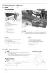
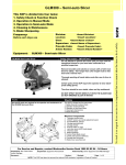
Service Manual
2005 500 Series (569) Self Propelled Walk Behind Mower
NOTE: These materials are for use by trained technicians who are experienced in the service and repair of outdoor power
equipment of the kind described in this publication, and are not intended for use by untrained or inexperienced individuals.
These materials are intended to provide supplemental information to assist the trained technician. Untrained or inexperienced individuals should seek the assistance of an experienced and trained professional. Read, understand, and follow all
instructions and use common sense when working on power equipment. This includes the contents of the product’s Operators Manual, supplied with the equipment. No liability can be accepted for any inaccuracies or omission in this publication,
although care has been taken to make it as complete and accurate as possible at the time of publication. However, due to
the variety of outdoor power equipment and continuing product changes that occur over time, updates will be made to these
instructions from time to time. Therefore, it may be necessary to obtain the latest materials before servicing or repairing a
product. The company reserves the right to make changes at any time to this publication without prior notice and without
incurring an obligation to make such changes to previously published versions. Instructions, photographs and illustrations
used in this publication are for reference use only and may not depict actual model and component parts.
© Copyright 2005 MTD Products Inc. All Rights Reserved
MTD Products Inc - Product Training and Education Department
FORM NUMBER - 769-02088
10/2005
TABLE OF CONTENTS
Introduction ........................................................................................................................... 1
Belt Removal ........................................................................................................................ 1
Blade Removal ..................................................................................................................... 3
Traction Control Cable Removal .......................................................................................... 3
Engine Control Cable ........................................................................................................... 4
Transmission Removal/Replacement ................................................................................... 5
Rear Discharge Door Removal/Replacement ...................................................................... 6
Servicing Front Wheel Brackets ........................................................................................... 9
1
2
SERIES 569 SELF PROPELLED
SERIES 569 SELF PROPELLED
1.
INTRODUCTION
2.
BELT REMOVAL
1.1.
Disclaimer: This service manual was intended
for the use, by trained technicians. The information contained in this manual is current and
accurate at the time of writing, but is subject to
change without notice.
2.1.
Disconnect and ground the spark plug wire.
2.2.
Drain out any fuel that is in the fuel tank.
2.3.
Remove the two hex head shoulder screws that
secure the belt guard using a 1/4” driver.
See Figure 2.3.
1.2.
Description: The 569 is a multi function frontwheel-drive self propelled lawn mower. This
mower features 12” rear wheels and will bag,
mulch, or side-discharge the grass using the
included grass defector. See Figure 1.2.
1/4” hex
Shoulder screws
Figure 2.3
2.4.
Figure 1.2
Squeeze the belt cover inward from both sides
of the cover to release the lock tabs.
See Figure 2.4.
Locking Tabs
Figure 2.4
NOTE: Tabs on both sides of the cover that
secure in each front wheel height adjuster.
1
SERIES 569 SELF PROPELLED
2.5.
2.7.
Loosen the belt guide with a pair of 7/16”
wrenches. See Figure 2.5.
Position the mower on its left side to keep the air
cleaner and carburetor elevated.
NOTE: Due to the orientation of the vent on the
transmission positioning the mower on its left
side is also advisable
2.8.
Belt Guide
Pull the belt in towards the rear of mower deck.
See Figure 2.8.
Holes for
tabs on belt cover.
Figure 2.5
NOTE: The belt guide dose not need to be
removed simply loosen enough to allow the belt
to clear the pulley.
NOTE: Notice the holes on each of the wheel
brackets designed to stabilize the belt cover.
2.6.
Figure 2.8
2.9.
Slip the belt off of the transmission pulley.
See Figure 2.6.
Figure 2.6
Remove the old belt from the crank shaft this
can be done with the blade still on the machine.
See Figure 2.9.
Figure 2.9
NOTE: It may be necessary to spin the blade to
allow the belt to fit between the blade tip and the
deck.
2
SERIES 569 SELF PROPELLED
2.10. When installing the new belt be sure that the belt
is riding within the belt keepers.
See Figure 2.10.
Belt Keepers
4.
TRACTION CONTROL CABLE REMOVAL
4.1.
Disconnect and ground the spark plug wire.
4.2.
Remove the belt cover.
4.3.
Disconnect the Z-fitting from the cable to the stationary bracket. See Figure 4.3.
Figure 2.10
3.
BLADE REMOVAL
3.1.
Disconnect and ground the spark plug wire.
3.2.
Drain the fuel tank or place a piece of plastic
under the fuel cap to prevent gas from leaking.
3.3.
Tip the mower on its side so the air cleaner is up.
3.4.
Secure the blade from rotating with a block of
wood or a blade lock.
See Figure 3.4.
Figure 4.3
NOTE: Slight back pressure will give the cable
slack to disconnect the Z- fitting easily.
NOTE: The cable end is barbed, and fits into a
snap-in cable mount to hold the cable in place.
NOTE: A Ford fuel-line disconnect tool is handy
for releasing barbed cable ends.
4.4.
Squeeze the tabs together to allow the cable to
slip through the bracket.
4.5.
Cut the cable ties to remove them from the handle. Replace them with new ones during installation.
4.6.
Loosen the wing nuts that secure the upper handle to the lower handle, and carefully fold the
upper handle upward for easy access to the bottom of the self-propel control housing.
NOTE: Use caution not to kink the control
cables.
Figure 3.4
NOTE: Torque for crack shaft bolt is 450-600
inch pounds
3
SERIES 569 SELF PROPELLED
4.7.
Remove the two Phillips head screws on the bottom of the control panel housing. See Figure 4.7.
5.
ENGINE CONTROL CABLE
5.1.
Push the bail handle to the forward limit of its
travel to give the cable slack.
5.2.
Disconnect the z-fitting from the bail handle.
5.3.
Disconnect the z-fitting from the engine.
NOTE: The cable is held secure with a snap
mount. Squeeze the tabs together to allow the
cable to back out of the bracket.
See Figure 5.3.
Snap mount
Figure 4.7
4.8.
Once the screws have been removed, take the
cover off to expose the cable end of the handle.
See Figure 4.8.
Figure 5.3
5.4.
Snap the handle bar fitting off of the handle bar.
The handle bar fitting is part of the control cable.
See Figure 5.4.
Figure 4.8
NOTE: Having the lever in a neutral position
releases cable tension, easing cable removal.
4.9.
Assemble mower by reversing the removal procedures.
Figure 5.4
5.5.
4
Install cable by reversing the removal procedures.
SERIES 569 SELF PROPELLED
6.
TRANSMISSION REMOVAL/REPLACEMENT
6.1.
Remove the belt cover by removing the shoulder
screws, squeeze the housing together to clear
the tabs that go into the wheel bracket.
6.2.
Loosen the belt guide and take the belt off of the
transmission pulley.
6.3.
Disconnect the drive cable from the cable
mounting bracket and transmission.
6.4.
Disconnect the return spring.
See Figure 6.4.
6.7.
When removing the drive gears be careful of the
dowel pins not to lose them. See Figure 6.7.
Dowel Pin
Figure 6.7
NOTE: The drive gears have an “R” and “L” on
the outer edge for side indicators.
Return Spring
6.8.
Remove the dust cover.
6.9.
Remove left side front wheel height adjuster and
loosen the bolts that hold right side front wheel
height adjuster to the deck. See Figure 6.9.
Figure 6.4
NOTE: Notice the orientation of the spring prior
to disconnecting.
6.5.
Remove the Wheels with a 9/16” socket.
6.6.
Remove the snap ring that holds the drive gear
in place. See Figure 6.6.
Figure 6.9
Snap Ring
NOTE: Tilt the left side of the transmission and
twist the transmission back to remove from the
right wheel bracket.
Figure 6.6
5
SERIES 569 SELF PROPELLED
6.10. Install the transmission in reverse order of disasembly. See Figure 6.10.
7.
REAR DISCHARGE DOOR REMOVAL/
REPLACEMENT
7.1.
Elevate the rear of mower with a couple of 4X4
blocks or similar material. See Figure 7.1.
Figure 6.10
NOTE: Make sure the front baffle is lined up with
the bolt holes for the front wheel brackets
Figure 7.1
7.2.
NOTE: Upon installation apply a high quality
axle grease to the shaft. and the inner side of the
bearing sleeve.
Prior to elevating, position the rear height adjusters in third notch from the top to expose the
mounting hardware. See Figure 7.2.
6.11. Examine both sleeve spacers for damage or
excessive wear. See Figure 6.11.
Figure 7.2
Figure 6.11
6.12. Assemble mower by reversing the transmission
removal procedures.
6
SERIES 569 SELF PROPELLED
7.3.
Remove both wheels with a 9/16” socket.
See Figure 7.3.
7.6.
Remove the 2 socket head screws from the rear
on the mower using a T-80 Torx driver.
See Figure 7.6.
Socket head screws
Figure 7.3
Figure 7.6
NOTE: The height adjuster lever can remain on
the wheel brackets. They have been removed in
this manual for visibility purposes.
7.4.
NOTE: Lift The deck slightly to free the rear baffle from the back of the deck. This will give clearance to reach the flange nuts on inner deck.
Remove the wing nuts and hairpin clips that hold
the handle on the handle brackets.
See Figure 7.4.
7.7.
Remove both flange nuts and bolts that were
obscured behind the rear baffle.
See Figure 7.7.
Wing nut
9/16”
Flange nuts
Hairpin Clip
Figure 7.4
7.5.
Figure 7.7
Lay the handle forward out of the work area.
7
SERIES 569 SELF PROPELLED
7.8.
7.10. Remove the self tapping screws that stabilize
handle brackets on each side of the deck.
See Figure 7.10.
Discharge the torsion springs that hold the rear
door closed. See Figure 7.8.
Self-tapping screw
3/8” wrench size
9/16” wrench size
Figure 7.8
Figure 7.10
NOTE: Use a screw driver to release the torsion
spring, discharging the tension.
7.9.
7.11. Slide the rear door out from between the handle
brackets.
Remove the top hex head screw that holds each
end of the pivot rod to the handle bracket.
See Figure 7.9.
7.12. Upon installation remember the spacers that fit
inside of the springs. See Figure 7.12.
3/8” Wrench
Hex Head
Pivot Rod
Torsion Springs
Spacers
Figure 7.9
Figure 7.12
8
SERIES 569 SELF PROPELLED
7.13. When reinstalling the torsion spring, use a piece
of rope or a spring puller to pull back on the
spring to avoid the possibility of injury.
See Figure 7.13.
8.2.
After removing the wheel bracket you will need
to take off the snap ring that holds the assembly
together. See Figure 8.2.
Figure 8.2
Figure 7.13
NOTE: The height adjustment assembly is
spring loaded by a wave washer.
8.3.
8.
SERVICING FRONT WHEEL BRACKETS
8.1.
In some cases the front wheel brackets may
need to be serviced. See Figure 8.1.
After the snap ring is remover the assembly will
come apart very easily. See Figure 8.3.
Bearing
Sleeve
Height Index
Bracket
Wave Washer
Height Adjustment
Lever
Wheel Axle
Flat Washer
Figure 8.3
Figure 8.1
9
SERIES 569 SELF PROPELLED
8.4.
8.7.
During reassembly it may be necessary to compress the wave washer in order to reinstall the
snap ring. See Figure 8.4.
Center the wrench to allow enough room to put
the snap ring on. See Figure 8.7.
Wrench
Snap Ring
Figure 8.7
Figure 8.4
NOTE: Prior to reassembling replace the wave
washer p/n 736-0447 with a new one if the original has lost tension.
8.5.
Use a bench top vise with a 1 1/4” open-end
wrench and a deep 1” socket See Figure 8.5.
1-1/4 open end wrench
Deep 1” socket
Figure 8.5
8.6.
Use the Socket to press against the sleeve bearing side of the bracket. Use the wrench to
press against the flat washer.
10