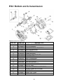
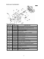
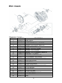
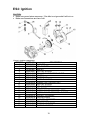
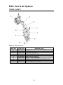
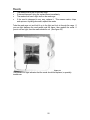
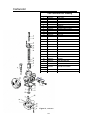
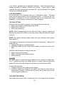
1
2003 CH2
Owners / Service Manual
“CHAMPIONS START HERE”
For parts orders contact your local dealer
To locate your closest Cobra dealer
log on to
www.cobramotorcycle.com
or call
(330) 549-9600
If you need technical assistance
contact your local dealer or call
the Cobra Technical Support Hotline at
(330) 549-9603
Cobra Motorcycle MFG., Inc.
11511 Springfield Road
North Lima, Ohio 44452
MCCH2003.1
1
DISCLAIMER OF WARRANTY
This motorcycle is sold “as is” with all faults, obvious or not. There are no warranties
expressed or implied, including any warranty of merchantability and warranty of fitness
for any particular purpose.
“WARNING”
THE COBRA CH2 IS A COMPETITION MODEL ONLY AND IS NOT
MANUFACTURED FOR, NOR SHOULD IT BE USED ON PUBLIC STREETS, ROADS
OR HIGHWAYS.
THE USE OF THIS BIKE SHOULD BE LIMITED TO PARTICIPATION IN
SANCTIONED COMPETITION EVENTS UPON A CLOSED COURSE BY A
SUFFICIENTLY SKILLED RIDER AND SHOULD NOT BE USED FOR GENERAL
OFF-ROAD RECREATIONAL RIDING.
IMPROPER USE OF THIS MOTORCYCLE CAN CAUSE INJURY OR DEATH.
THIS BIKE IS INTENDED FOR EXPERIENCED RACERS ONLY AND NOT FOR
BEGINNERS.
IT IS YOUR RESPONSIBILITY AS THE OWNER OF THIS COBRA MOTORCYCLE
OR AS THE PARENT, OR LEGAL GUARDIAN OF THE OPERATOR, TO KEEP THIS
COBRA MOTORCYCLE IN PROPER OPERATING CONDITION.
THIS BIKE WAS DESIGNED FOR RIDERS THAT WEIGH LESS THAN 80 LBS WITH
FULL RIDING GEAR AND SHOULD NOT BE OPERATED BY RIDERS THAT WEIGH
MORE THAT.
BE SURE THAT THE RIDER ALWAYS WEARS ADEQUATE SAFETY GEAR
EVERYTIME HE OR SHE RIDES THEIR COBRA MOTORCYCLE.
IMPORTANT SAFETY NOTICE
Failure to follow WARNING instructions could result in severe injury or death to
the machine operator, a bystander, or a person inspecting or repairing the
machine.
CAUTION:
A CAUTION indicates special precautions that must be taken to avoid damage to
the machine.
NOTE:
A NOTE provides key information to make procedures easier or clearer.
2
Table Of Contents
General Information .........................................................................................................4
Specifications - General..............................................................................................4
Break-In Procedure ......................................................................................................6
Starting Procedure .......................................................................................................7
General Tips..................................................................................................................8
Maintenance......................................................................................................................9
Schedule & Tips ...........................................................................................................9
M1: Replacing Transmission / Clutch Lubricant ....................................................10
M2: Chain adjustment................................................................................................11
M3: Fork Oil Replacement ........................................................................................12
M4: Clutch Adjustment ..............................................................................................13
Engine Service / Parts ...................................................................................................14
ES1: Top End Parts ...................................................................................................15
ES2: Bottom end & transmission.............................................................................16
ES3: Clutch .................................................................................................................18
ES4: Ignition................................................................................................................19
ES5: Cooling System .................................................................................................20
ES6: Fuel & Air System .............................................................................................21
ES7: Exhaust ..............................................................................................................26
Chassis Service / Parts .................................................................................................27
CS1: Suspension........................................................................................................27
Troubleshooting ..............................................................................................................29
3
General Information
Specifications - General
Items
CH2
Dimensions
Wheelbase
41” (1040 mm)
Wheel size
10” (254 mm) rear, 12” (305 mm) front
Seat height
26” (660 mm)
Engine
Type
2-stroke, single cylinder, reed valve
Cooling system
Liquid-cooled
Displacement
49.8 cc
Bore and stroke
39 mm x 41.7 mm
Ignition system
Digital Electronic
Spark plug
Champion C53, NGK B11EGV
Gap 0.023” – 0.025” (0.58 – 0.64 mm)
Fuel type
Sunoco MO2 X or 93 octane pump gasoline
OTHER RACE FUELS ARE NOT RECOMMENDED
Oil type
Cobra Venom 2-cycle Race Oil
Fuel / oil mix ratios
Between 32:1 and 40:1 (after engine Break-In is
complete)
Ignition timing
Fixed
Carburetion
19 mm Dell’Orto PHBG - PS
Main jet 90
Slow (Pilot) jet 48
Float height 16mm + 0.5mm (0.63” + 0.020”
Transmission
Speed
Single
Clutch
3 shoe centrifugal
Final drive ratio
10/39 T
Transmission / clutch oil type
Cobra Venom 3 Shoe Clutch Milk, or Dexron III
Quantity 250 ml (8.5oz)
4
Chassis
Front tire
2.50 - 12
Pressure 15 psi minimum
Rear tire
2.75 - 10
Pressure 15 psi min. (20 psi for hard pack or rocky conditions)
Front fork
Marzocchi 32mm
Fork oil type SAE 20 weight
Fork oil amount 200 ml (6.8 oz) oil change, 220 ml (7.4 oz) rebuild
Fork oil height 70 mm (2.75”) collapsed from top with spring (no
spacer)
5
Break-In Procedure
Your Cobra CH2 is a close-tolerance high performance machine and break-in
time is very important for maximum life and performance. The CH2 can be ridden
hard after the first ½ hour break-in time but it is recommended that no
adjustments are made to the carburetion or suspension until the full 8 hours of
bike break-in has elapsed. Also, after the engine, transmission, and drive train
have been broken-in for the full 8 hours, the bike will be faster!
Fill the fuel tank with 93 octane pump gas, or Sunoco MO2X without oil. Also, fill
the oil injection reservoir with Cobra’s specially formulated Cobra Venom 2-cycle
Race Oil. (Part # MCMUOL02)
CAUTION:
Failure to use proper fuel or oil may result in premature engine wear, or damage
to the machine.
Adhering to the following break-in schedule will result in long lasting high
performance machine.
•
•
•
•
First ½ hour of operation
o
Follow the starting procedure listed in this manual.
o
Avoid prolonged operation at Wide Open Throttle.
After 1 hour of operation
o
Check for loose bolts and nuts on the bike and retighten as
necessary (proper toque values are listed under Specifications).
o
Clean the carburetor bowl.
o
Change the transmission / clutch lubricant.
After 8 hours of operation
o
Change the fork oil.
o
Have a Certified Cobra Mechanic change the shock oil.
Your bike is now ready for the highest level of competition!
6
Starting Procedure
Before starting the machine inspect the following:
•
•
•
•
•
•
•
•
•
•
•
•
Fill the 2-stroke injector oil reservoir with Cobra’s specially formulated Cobra
Venom 2-cycle Race Oil.
Insure that the fuel tank contains an adequate volume of fuel to complete
the distance required. (Sunoco MO2X or 93 octane pump gas).
Check for proper tire pressure in both tires.
Observe the chain tension and adjust if necessary.
Observe the coolant level and fill if necessary.
Verify that the chain rollers do not have improper wear.
Inspect the frame for;
o
Cracks in the metal.
o
Cracking paint which might indicate overly stressed material.
Verify that the handlebars are tight.
Check the throttle for;
o
Smooth operation and sound closing.
o
Frayed strands of the cable inside the throttle housing.
Check for loose bolts and nuts, and re-torque as necessary.
Verify that the air filter is clean and properly saturated with oil.
Turn the fuel on by rotating the fuel petcock knob to the vertically downward
position (reserve position is horizontally forward).
CAUTION:
For best results from your Cobra Motorcycle use only the recommended fuels.
Testing has shown that most ‘race’ fuels actually degrade performance.
When your pre-ride inspection is complete the bike may be started. For a cold
engine follow this procedure.
1.
2.
3.
4.
5.
6.
Place the motorcycle on a stand of sufficient strength that positions the
motorcycle in a level upright position with the rear wheel off the ground.
On the carburetor, flip the black choke knob upward from the right side of
the bike.
Kick start the engine by kicking the lever forward.
Rev the engine in short spurts, turning the throttle no more than 1/4 open
until the engine will run without the choke.
Verify a functional engine shut-off switch by shutting off the engine.
Restart the engine and proceed with riding when the engine is sufficiently
warm (i.e. the side of the cylinder is warm to touch).
CAUTION:
Never rev an engine full throttle when it's cold or slightly warmed up. Cobra
recommends that you tell your child to take it easy the first couple of minutes in
practice until the engine comes up to full operating temperature. Make sure your
engine is properly warmed up before racing.
7
General Tips
1.
2.
3.
4.
5.
6.
Always wear a helmet and other protective riding gear.
Cobra recommends that you tell your child to take it easy the first couple of
minutes in practice until the engine comes up to full operating temperature.
Make sure your riders’ foot is not resting on the foot brake while they are
riding .
Evaluate the bikes jetting only after it has been warmed up to race
temperatures.
A properly maintained machine is safer, faster, and more fun to ride.
When washing the bike, be careful to not directly aim the hose at the
bottom edge of the seat, or water is apt to enter the airbox.
8
Maintenance
Schedule & Tips
It is important that you adhere to this maintenance schedule so as to promote the
longevity of your Cobra Motorcycle.
•
•
•
Between each ride
o
Fill the 2-stroke injector oil reservoir.
o
Check the air filter (clean and re-oil as necessary).
o
Insure the smooth operation of the throttle cable (throttle soundly
‘clacks’ shut).
o
Check for frayed strands of the throttle cable inside the throttle housing
and replace if necessary.
o
Check for adequate tire pressures and adjust if necessary.
o
Check all nuts and bolts for proper torque and re-torque if necessary.
o
Spray all moving parts with WD40 or other light oil.
o
Check drive chain for
§
Proper tension and adjust if necessary.
§
Adequate lubrication and lubricate if necessary.
o
Insure that the ignition stator and rotor are clean and dry.
o
Check the frame for cracks in the metal or cracks in the paint that
might indicate that the metal has been stressed beyond it’s safe limits.
Replace or get properly rewelded as necessary.
o
Fill the 2-stroke injector oil reservoir with Cobra’s specially formulated
Cobra Venom 2-cycle Race Oil.
Every 2 hours of operation
o
Replace the transmission oil.
Every 10 hours of operation
o
Replace the fork oil.
o
Have the shock oil replaced by a Certified Cobra Mechanic.
CAUTION:
1.
If you ever need to weld anything on the bike, disconnect the spark plug
cap, unplug the ignition, disconnect the kill switch, scrape the paint bare
near the area to be welded and put the ground clamp as close to the area
to be welded as possible.
9
Be sure the fuel tank and carburetor have been removed and safely located
away from the welding process.
2.
The frame is 4130 Chrome Moly and it is important to weld it with the proper
rod and heat settings set as light as possible. Cobra recommends replacing
the frame with a new one if the old one becomes damaged.
M1: Replacing Transmission / Clutch
Lubricant
Tools needed:
• 250 ml (8.5oz) Cobra Venom 3 Shoe Clutch Milk (Part # MCMUGF01) or
Dexron III Automatic Transmission Fluid
• #3 Phillips screwdriver
• large flat blade screwdriver or coin
Procedure:
1. Begin this procedure with a bike that has been ridden more than 5 minutes
but less than 10 minutes. It is desired to have the engine warm enough so
that the oil ‘runny’ but not so hot that there is risk of being burned by the
engine or the oil.
Hot oil and hot components on the motorcycle may cause burns.
2. Lean bike against something or set on stand with oil drain hole.
3. Using Phillips screwdriver, remove the oil drain bolt located on the right side
of the engine (figure 1).
Figure 1
10
NOTE: You may need to adjust the brake pedal (up or down) to gain access to
the drain bolt.
4. After it has drained, reinstall the drain screw with gasket.
5. Refill oil from oil fill plug 250 ml (8.5oz) Cobra Venom 3 Shoe Clutch Milk
(Part # MCMUGF01), or Dexron III Automatic Transmission Fluid, thru the fill
plug.
NOTE: Leaning the bike over onto it’s left hand side will facilitate the oil filling
procedure.
6. Reapply the oil fill screw, securely, being sure the gasket is in place.
CAUTION:
Cobra has spent considerable time and money developing the proper lubrication
to handle the harsh environment of the automatic clutch and transmission of this
motorcycle. Cobra was forced to put forth this effort because the other available
options and not adequate. Cobra’s specially developed Cobra Venom 3 Shoe
Clutch Milk (Part # MCMUGF01) is the recommended lubricant for your CH2
motorcycle.
M2: Chain adjustment
Tools required for chain adjustment
•
•
Two 19 mm wrenches or sockets
13 mm wrench or socket
1. Make sure that the
rear wheel is aligned
properly.
2. For
proper
adjustment, the chain
should have 35 mm
(1
3/8”)
free
movement
just
behind
the
chain
block with no load on
the bike (figure 2)
Figure 2
CAUTION:
Verify that the chain has a minimum of 6mm (1/4”) free movement when the
suspension is collapsed.
11
3. If the chain requires adjusting, loosen the axel
with a pair of 19 mm wrenches and tighten the
chain by rotating the adjuster bolts clockwise
(CW) or loosen the chain by rotating the adjuster
bolts (CCW).
4. Retighten the axel bolt to 25 ft-lb (34 Nm).
Figure 3
M3: Fork Oil Replacement
Tools required
•
•
•
5 & 6 mm Allen wrench
19 mm wrench or socket (two required)
Spring clip remover
Disassembly
1.
2.
3.
4.
Remove the front wheel.
Remove the fork legs from the triple clamps.
Perform the following on one leg at a time.
Using your hands, remove the black rubber plug from the top of the fork leg
exposing the white plastic cap.
5. Secure the fork leg assembly in a vice by gripping the leg across the flats
through which the axle bolt goes through.
6. Depress the white plastic cap inwards (down) and remove the wire spring clip
from its groove.
7. Remove the white cap, the fork spring preload sleeve, and the fork spring.
NOTE: Depressing the fork leg will facilitate removing the white cap.
8. The fork can now be turned upside down and drained.
Assembly
1. Fill the leg with 200 cc (6.8 oz) 20 wt fork oil.
2. Standard fork oil level is 70 mm (2.75”) from the top edge with the fork
collapsed.
NOTE: Remove the preload sleeve but leave the spring in for the measurement.
3. Install the preload sleeve.
4. Install and depress the white cap while installing the spring clip.
5. Fork may be reinstalled.
12
M4: Clutch Adjustment
Tools required
6 mm hex key (Allen wrench)
large flat blade screw driver
Process
1. Remove the clutch adjustment access plug (6mm hex key).
Figure 4
2. Using the kick lever, turn the engine over (rotate the crank) until one of the
large flat head screws is visible through the access hole (this flat head screw
is one of the three adjusters).
NOTE: Turning the adjusting screw Counter Clock Wise (CCW) will allow the
shoe to engage at a lower RPM, this is the direction you should adjust to
compensate for shoe wear. Alternatively, a Clock Wise (CW) adjustment of the
screw will allow the clutch to engage at a higher RPM.
3. Subsequently use the kick lever to rotate the crank and expose the other two
clutch shoe adjusters and adjust them by the same amount.
CAUTION:
Be sure to adjust each of the three shoe adjustors by the same amount.
4. Reinstall the clutch adjust access plug (10 ft-lb, 14 Nm).
13
Engine Service / Parts
Factory trained technicians with precision gauging and proper assembly fixtures
carefully assemble all Cobra engines to specific clearances. If you feel you have
the skills, and the appropriate tools, to perform the following service tasks please
follow the instructions closely. The part numbers are listed throughout to help you
when ordering parts from your local Cobra dealer.
If you don’t feel comfortable with the service work, simply take your engine out of
the frame and sent it to:
Cobra Precision Engines
11511 Springfield Road
North Lima, Ohio 44452
Cobra’s technicians will go through the entire engine, replacing gaskets, bolts,
any old part that is worn. The engine will be rebuilt using the same precision
gauging and assembly fixtures as when it was assembled new. Before leaving,
the engines performance will be measured on a dynamometer to ensure that
your engine is operating at its highest potential. All this for one low nominal fee,
plus cost of parts. Call (330) 549-9603 for details.
14
ES1: Top End Parts
Figure 5, Top End Components
REF NO
1
2
3
4
5
6
7
9
10
11
12
13
14
PART NO
ECMOTE01
ECMOTE02
HCBC0603
HCNF0601
ECMOTE05
ZCMOTE06
ECMU0026
ECMOTE09
ZCMOTE10
ZCMOTE11
ECMU0056
ECMU0076
ECMUSR04
DESCRIPTION
CYLINDER - CHROME
PISTON KIT - SINGLE RING
6X30 CAP SCREW
FLANGED NUT 6MM
CYLINDER HEAD
CYLINDER HEAD O-RING
6MM DOWEL
CYLINDER HEAD STUD BOLT 6MM
BASE GASKET
O-RING - EXHAUST FLANGE
PISTON RING - CAST
WRIST PIN
SNAP RING-FRANCO PISTON
15
ES2: Bottom end & transmission
Figure 6, bottom end components
REF NO
1
2
3
4
5
6
7
8
9
10
11
12
13
14
15
16
17
18
PART NO
ECMCBE01
ECMOBE02
ECMOBE03
ECMOBE04
ECMOBE05
ECMU0016
ECMOBE07
ECMOBE08
ECMU0077
HCBC0660
HCBC0607
ZCMOBE12
ECMOBE13
ECMOBE14
DESCRIPTION
CASES - COMPLETE SET
OUTPUT BEARING
OUTPUT BEARING - SNAP RING
PRECISION BEARING
CRANK SEAL
CRANK BEARING
CRANKSHAFT COMPLETE
FLYWHEEL KEY
WRIST PIN BEARING
6X60 CAP SCREW
6X50 CAP SCREW
CRANKCASE GASKET
OUTPUT SEAL
ROD WITH WRIST PIN AND BEARING
S6 V/EC.+COM. SET OF SEAL
ZKMOBE16 GASKET KIT
ECMOBE17 DOWEL PIN - CASE
ECMOBE18 CASE VENT PIPE
16
Kick lever mechanism
Figure 7, kick mechanism
REF NO
1
2
3
4
5
6
8
9
11
12
13
14
15
16
17
18
19
20
21
22
PART NO
ECMOKS01
ECMOKS02
ECMOKS03
ZCMU0001
ECMU0037
ECMOKS06
HCBC0625
ECMCKS09
HCBC0603
ZCMOKS12
ECMOKS13
ECMOKS14
ECMOKS15
ECMOKS16
ECMOKS17
ECMOKS18
ECMOKS19
ECMOKS20
ECMOKS21
ECMOKS22
DESCRIPTION
CLUTCH COVER
CRUSH WASHER - WATER DRAIN PLUG
WATER DRAIN PLUG - 6X8
OIL FILL PLUG GASKET
OIL FILL PLUG
RETAINER CLIP - THRUST WASHER
6X25 CAP SCREW
KICK START LEVER
6X30 CAP SCREW
CLUTCH COVER GASKET
THRUST WASHER
SEAL - KICK START SHAFT
KICK START SHAFT WITH GEAR
KICK START SPRING
WASHER - RETURN SPRING RETAINER
RETAINER CLIP - RETURN SPRING
J-SPRING KICK START
DOG GEAR
GASKET - ADJUSTING PLUG
ADJUSTING PLUG
17
ES3: Clutch
Figure 8 Clutch components
REF NO
1
2
3
4
5
6
7
9
10
11
12
13
14
15
16
17
18
19
21
22
23
24
PART NO
ECMOCL01
ECMCCL02
ECMOCL03
ECMOCL04
ECMOCL05
ECMOCL06
ECMOCL07
ECMOCL09
PCMOCL10
ECMOCL11
ECMOCL12
ECMOCL13
ECMOCL14
ECMOCL15
ECMOCL16
ECMOCL17
ECMOCL18
ECMOCL19
ECMOCL21
ECMOCL22
ECMOCL23
ECMOCL24
DESCRIPTION
GEAR - DRIVE
SNAP RING
CLUTCH START NUT - LH THREAD
WASHER - CLUTCH NUT BACK UP
CLUTCH COMPLETE
SPACER - CLUTCH TO HUB
BUSHING - CLUTCH HUB
WASHER - CLUTCH BASKET BACK UP
SPROCKET - 10 TOOTH
SNAP RING - OUTPUT SHAFT
CLUTCH BASKET WITH GEAR
S6 TCBEI M5X14 SCREW FOR MASS.
ADJUSTING SPRING
S6 D.2,5 BALL
S6 SPECIAL-SCREW
FEDER ATAZZA 6.2X12X0.6 DIN 2093
CLUTH WASHER
CLUTCH SHOE
S6 CLUTCH PAWL
CLUTCH SCREW COUPLING
S6 CLUTCH SPRIG
BUSH
18
ES4: Ignition
CAUTION:
• Make sure ground wires are secure. If the bike is not grounded it will not run.
• Make sure connections are free of dirt.
Figure 9, ignition components
REF NO
1
2
3
4
5
6
7
8
9
11
12
13
14
15
16
18
20
21
23
24
PART NO
ECMOIG01
HCWF0801
HCNS0801
HCBC0401
ECMOIG05
ECMOIG06
ECMOIG07
ECMOIG08
ECMOIG09
HCBC0502
HCBC0550
ECMOIG13
ECMOIG14
ECMOIG15
ECMOIG16
ECMOIG18
ECMOIG20
HCWF0501
ECMOIG23
ECMOIG24
DESCRIPTION
FLYWHEEL
8MM WASHER
8MM NUT
4X10 CAP SCREW
COIL WITHOUT SPARK PLUG CAP
CDI BOX
SPARK PLUG
SPARK PLUG CAP
RUBBER FOR CONTROL UNIT
5X20 CAP SCREW
5X50 CAP SCREW
7MM DOWEL
IGNITION COVER GROMMET - OPEN
IGNITION COVER GROMMET - CLOSED
SPACER - FLYWHEEL
IGNITION COVER
FLYWHEEL GROMMET
5MM WASHER
SPARK PLUG RUBBER
SPARK PLUG BOOT
19
ES5: Cooling System
Water pump
Figure 10 water pump
REF NO
1
2
3
4
5
6
7
9
11
12
13
14
15
PART NO
ECMOWP01
ECMOWP02
ECMOWP03
ECMOWP04
ECMOWP05
ECMOWP06
ECMPWP07
ECMPWP09
ECMOWP11
ECMOWP12
ECMOWP13
ECMOWP14
ECMPWP15
DESCRIPTION
WATER PUMP SHAFT
RETAINER CLIP - WATER PUMP BEARING
BEARING WATER PUMP
SPACER - WATER PUMP BEARING
CRANK PULLEY
WATER PUMP BELT
CLAMP FOR OIL TUBE
OIL INJECTOR MOUNT PLATE
WATER PUMP IMPELLER
SNAP RING - TOOTHED
WATER PUMP SEAL
WASHER - BEARING RETAINER
DOWEL PIN
20
ES6: Fuel & Air System
Intake system
Figure 11, Intake components
REF NO
1
2
3
4
5
6
8
9
10
PART NO
RCMU0018
ECMOIN02
HCBC0625
ECMOIN04
ZCMOIN05
ECMOIN06
ECMOIN08
ECMOIN09
ECMOIN10
DESCRIPTION
19MM Dell’Orto PHGB CARBURETOR
CLAMP
6X25 CAP SCREW
REED SPACER PLATE
REED VALVE GASKET
REED VALVE ASSEMBLY
SCREW - REED CAGE TO SPACER PLATE
RUBBER INTAKE BOOT
INTAKE RETAINING PLATE
21
Reeds
•
•
•
•
The reeds must lay flat on the reed cage.
If the reed tips aren’t lying flat, replace them immediately.
The reeds must have a tight seal on the reed cage.
If the reed is damaged in any way, replace it. This means cracks, chips,
and ruptures. Anything abnormal, replace the reeds.
Take the reed cage out and hold it up to the light and look in through the cage. If
you see light between the reed pedals and the frame, then replace the reeds. If
you do not see light, then the reeds should be ok. (See figure 25)
Figure 12
The presence of light indicates that the reeds should be replaced, or possibly
turned over.
22
Carburetor
CH2 Carburetor Ref. Drawing
REF. #
1
2
3
4
5
6
7
8
9
10
11
12
RCMU0301
RCMU0102
RCMU0003
DESCRIPTION
CARB SLIDE
NEEDLE
ATOMIZER
MAIN JET (STOCK 90)
PILOT JET (STOCK 48)
CHOKE JET
FLOAT
RUBBER CABLE CAP SEAL
CABLE ADJUSTER
RCMU0006
RCMU0106
TOP CARB SCREW
CARB TOP
13
ZCMU0007
TOP CARB GASKET
14
RCMU0004
SLIDE SPRING
15
RCMU0205
NEEDLE RETAINER PLATE
16
RCMU0007
NEEDLE CLIP
17
RCMU0204
CHOKE ASS’Y. 2001 CM
20
RCMU0009
FUEL MIXTURE SCREW
21
RCMU0011
IDLE ADJUSTMENT SCREW
25
RCMU0103
FLOAT BOWL GASKET
26
RCMU0107
FLOAT NEEDLE
27
RCMU0012
DIFFUSER
28
RCMU0016
FLOAT RETAINER PIN
29
RCMU0106
FLOAT BOWL
RCMU0201
BOTTOM FLOAT SCREW
RCMU0269
VELOCITY STACK
30
31
33
PART #
RCMU0305
RCMU0601
RCMU0002
RCMU0090
RCMU0048
Figure 13, carburetor
23
Your Cobra is equipped with an adjustable carburetor. Some fine-tuning may be
needed according to weather condition and altitude. Proper jetting is very
important for engine performance and engine life. Serious damage to the engine
can occur if not properly adjusted.
IDLE ADJUSTMENT:
On the left side of the carburetor, there are 2 adjustment screws. The larger
screw with the knurled head is the idle adjustment screw. To raise the idle, turn
the screw in clockwise (in 1/4 turn increments) and rev the engine after each
adjustment. To lower the idle, turn the screw counter-clockwise.
TOP END JETTING:
Indications that the engine is running too rich (too much fuel for the air) are:
• Engine not revving out or blubbering at high RPMs.
• Engine will not ‘clean out’
• Wet or black spark plug
NOTE: Before changing jetting be sure that the air filter is properly cleaned and
has the usual amount of air filter oil. An overly dirty air filter can cause the engine
to run rich.
NOTE: Also before changing jetting, insure that your carburetor has a proper
float height of 5
If the engine is running rich on the top end it should be leaned out. Leaning it out
can be done by:
1. Changing the main jet to a smaller number.
2. Raising the needle clip (this lowers the jet needle) one notch at a time on the
slide.
Indications that the engine is running too lean are:
• Engine cutting out on top end.
• Engine overheating and ultimately seizure.
• White spark plug
CAUTION:
It is much safer to operate the engine slightly rich as opposed to slightly lean.
This is because an overly rich engine will just run poorly while an overly lean
engine will seize, potentially causing an expensive top end rebuild and a DNF.
To richen the carburetor:
1. Change the main jet one number at a time (larger).
2. Lower the needle clip (raising the jet needle) one notch at a time until the
engine starts to blubber on the top end, then move the clip back up one notch
or until you get the blubber out.
FUEL MIXTURE SCREW
The smaller brass screw that is towards the front of the engine is a fuel mixture
24
screw. This screw will also richen and lean your engine more on the bottom and
mid-range. In warmer conditions, turn the screw in. In colder conditions, turn the
screw out. Be sure to keep the carburetor very clean and make sure you don't
have water or dirt in the carburetor bowl. Use automotive carburetor cleaner or
WD-40 to clean the carburetor inside and out.
STOCK CARBURETOR SETTINGS
The 2003 PW3 stock carburetor settings from the factory are:
• 48 pilot jet
• 90 main jet
Cleaning the carburetor:
Clean the carburetor in a well-ventilated area, and take care that there is no
spark or flame anywhere near the working area; this includes any appliance with
a pilot light. Because of the danger of highly flammable liquids, do not use
gasoline or low flash-point solvent to clean the carburetor.
1.
2.
3.
4.
Make sure the fuel is shut off.
Remove the carburetor.
Drain the fuel in the carburetor.
Disassemble the carburetor.
CAUTION:
Do not use compressed air on an assembled carburetor. Or the pressure may
deform the float. Do not use a strong carburetor cleaning solution, which could
attack the parts of the carburetor; instead, use a mild high cleaning solution safe
for plastic parts.
5. Immerse all the metal parts in a carburetor cleaning solution.
6. Rinse the parts in water.
7. After the parts are cleaned, dry them with compressed air.
8. Blow out the fuel passages with compressed air.
9. Assemble the carburetor
10. Install the carburetor onto the motorcycle.
NOTE:
The three most common problems with this
carburetor are (figure 14):
1. Installing the carburetor top backwards.
2. The carburetor slide indexing pin falling
out.
3. Either side vent elbow falling out.
Figure 14 Proper carburetor top
installation and location of rectangular
slide indexing pin and one of the elbows
that has been known to fall out.
25
ES7: Exhaust
The pipe is a crucial element to a motorcycle. Any kinks, dents, or damage done
to the pipe will result in a major performance loss.
NOTE:
Be sure to take the pipe off, and any carbon that may be built up. Carbon build
up is created from exhaust. Exhaust has oils in it, and the oils cling to the walls
of the inside of the pipe. Over a long period of time, the diameter of the pipe will
decrease, due to carbon build up. So it is essential to clear the residue.
CAUTION:
It is important to repack the silencer.
repacked are
•
The bike is louder than normal.
•
A loss of power.
Signs of your silencer needing to be
26
Chassis Service / Parts
CS1: Suspension
Front Forks
Figure 15
Because of different rider weights, sizes and riding styles, we offer various
suspension options:
See Optional Components section of this manual for details on these and other
optional components for your Cobra Motorcycle.
27
2003 CH2 FRONT FORK PARTS LIST
REF #
1
2
3
4
5
6
PART #
KCMZ0001
KCMZ0002
KCMZ0003
KCMZ0004
KCMZ0005
HCBC0806
7
8
9
11
12
13
14
15
16
17
18
18A
19
20
21
22
23
25
26
27
28
29
31
32
33
KCMZ0007
KCMZ0008
KCMZ0009
KCMZ0011
KCMZ0012
KCMZ0013
KCMZ0014
KCMZ0015
KCMZ0016
KCMZ0017
KCMZ0018
KCMZ0018A
KCMZ0019
KCMZ0020
KCMZ0021
HCWC0000
HCBC0806
KCMZ0025
KCMZ0026
KCMZ0027
KCMZ0028
KCMZ0029
KCMZ0031
HCBC0609
HCBC0525
DESCRIPTION
8 X 50 CS
TOP HANDLE BAR CLAMP
LOWER HANDLE BAR CLAMP
FORK PLUG – BLACK
TRIPLE CLAMP UPPER
8 X 30 CS PINCH BOLT FOR TOP
TRIPLE CLAMP
SNAP RING FOR FORK CAP
INNER FORK CAP - WHITE
O-RING UNDER FORK CAP
PRELOAD SLEEVE
FORK SPRING
SWIPER
SNAP RING
FORK SEAL
WASHER
SNAP RING FOR PISTON
PISTON ROD - REBOUND
PISTON ROD - COMPRESSION
REBOUND SPRING
FORK LEG OUTER LEFT
FORK LEG – 5 PIECE UNIT – LEFT
WASHER
8 X 30 CS
TRIPLE CLAMP BOTTOM W/STEM
FORK TUBE – INNER RIGHT
FORK TUBE – INNER LEFT
TOP OUT BUMPER
FORK LEG – OUTER RIGHT
FORK LEG – 5 PIECE UNIT – RIGHT
6 X 20 CS
6 X 25 CS
28
Troubleshooting
1) Engine not behaving properly
a) Carburetor top is installed backwards (happens a lot)
b) The carburetor slide indexing pin is missing
2) Engine is down on power
a) Clutch engagement is not set properly
b) Jetting is incorrect
c) Silencer needs repacked
d) Exhaust pipe
i)
Has excess carbon buildup
ii) Has large dent in it
e) Compression is low
i)
Piston
ii) Rings
f) Reeds are damaged
g) Ignition timing is incorrect
3) Engine is excessively loud
a) Silencer needs repacking
4) Engine ‘blubbers’ at high RPMs
a) Jetting too rich
5) Engine won’t start
a) Fuel
i)
None in tank
ii) Is sour or bad
b) Carburetor is dirty
c) Ignition
i)
Spark plug fouled
ii) Spark plug cap off
iii) Engine Shut-off ‘kill’ switch is shorted
iv) Bad electrical ground
v) Stator winding damaged
d) Exhaust is plugged
6) Engine won’t idle
a) Idle knob needs adjusted
b) Carburetor jets are dirty
29
Index
Bottom End
Service ...........................................16
Break-In................................................6
Carburetion
Specifications ..................................4
Chain
Adjustment.............................. 11, 12
Chassis
Specification....................................4
Clutch
Parts ...............................................18
Service ...........................................18
Clutch Lubricant
Replacing .......................................10
Cooling System.................................20
Engine
Parts List ........................................14
Specifications ..................................4
Exhaust ..............................................26
Fork Oil
Replacement .................................12
Front Forks
Service ...........................................27
Front Forks: .......................................27
Fuel
Petcock ............................................7
Fuel System
Parts list .........................................21
Service ...........................................21
General Tips........................................8
Ignition
Parts ...............................................19
Service ...........................................19
Jetting
How To ...........................................24
Stock.................................................4
Kick Lever ..........................................17
Lubrication
Recommended ...............................4
Maintenance
Schedule ..........................................9
Tips ...................................................9
Oil
Recommended ...............................4
Parts
Bottom end ....................................16
Clutch .............................................18
Ignition............................................19
Inlet .................................................21
Kick mechanism ...........................17
Reeds .............................................21
Top end ..........................................15
Water pump ...................................20
Parts List
Front Forks ....................................27
Petcock ................................................7
Reeds .......................................... 21, 22
Spark Plug
Recommended ...............................4
Specifications ......................................4
Starting .................................................7
TIps .......................................................8
Top End
Service ...........................................15
Transmission
Service ...........................................16
Specifications ..................................4
Transmission Lubricant
Replacing .......................................10
Troubleshooting ................................29
VIN reading .........................................8
WARNING ...........................................2
Water pump .......................................20
30