1
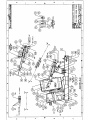
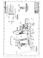
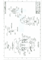
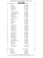
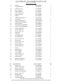
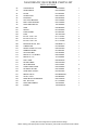
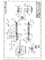
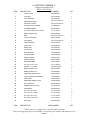
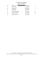
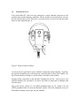
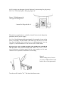
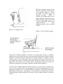
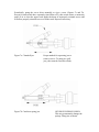
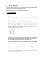
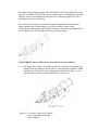
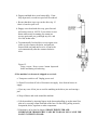
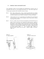
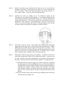
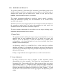
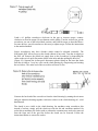
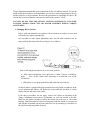
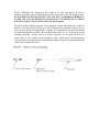
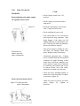
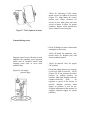
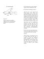
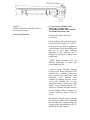
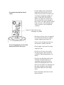
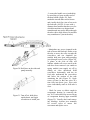
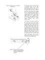
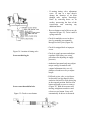
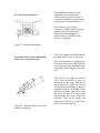
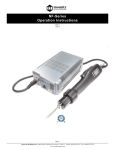
I. INTRODUCTION CONGRATULATIONS! You have just purchased the state of the art in Automatic Screw Feeding. The NASCOMATIC 2001 was designed by NASCO after years of exposure to other automatic screwfeeders. Problems endemic to all other screwfeeders have been eliminated resulting in a unit that is dependable, jam-proof and virtually maintenance free. There are several rules you should follow to ensure proper operation and long equipment lifetime. Rule 1: Don't adjust anything unless you have read the operation manual. Your machine has been factory adjusted and manufactured to high tolerances to minimize problems you are likely too encounter in a factory environment. Rule 2: Connect the device to 115 volt (60 Hz) for US models, 230 volt (50 Hz) for most non-domestic models. Check nameplate on to of drum shaft to identify correct type for your device. Rule 3: Provide a suitably clean (40 micron) and adequately pressured (80-90 psi) air supply. Some screwdrivers may require greater air pressure to develop adequate torque for your application. Check the supply air gage when you receive the machine and maintain the setting. Greater air pressure can be handled by reducing pressure supplied to the machine via the regulator located on the side of the drum strut. Adjustment is made by pulling out the knurled knob until it clicks and turning it clockwise to increase pressure supplied to the machine; counterclockwise to decrease pressure. The air pressure gage, "Supply Air Pressure,"located furthest from the drum, indicates supply air pressure. Rule 4: Make sure that the screws loaded into the drum are the size for which the machine was designed. Wrong sized screws and screws out of tolerance may jam the machine. Check each batch and remove any foreign material; i.e. wire, paper, plastic, wood, etc., before loading the drum. Rule 5: Remember, SAFETY FIRST. The screwfeeder works by pressurized air blowing a pointed object through a tube with a high velocity. NEVER POINT THE SCREWFEEDER AIR TUBE OR SCREWDRIVER AT ANYONE WHILE THE AIR IS ON OR TURNED ON. II. SAFETY INSTRUCTIONS 1. Safety and operation instructions should be read completely before equipment is operated. Retain for future reference. 2. Dry air supplied to the device will increase the useful lifetime of the screwfeeder and driver. The equipment should not be used near water. 3. Power supply cords should be routed so that they are not likely to be walked on or pinched. Ensure that air lines are not crimped by other equipment or the operator. A NASCO TOOL SUPPORT is recommended to keep air and sensor lines protected from blockage and out of the operator’s way. It also prevents damage to the driver from dropping. 4. Keep hands and loose clothing away from gears, belt driver and escapement cylinder and plunger on the automatic screw feeder and away from the "linearlock"mechanism, torque adjustment gear cover and driver jaws on the screwdriver. 5. The equipment should be connect to a 115 volt AC, (60 Hz) for U.S. models, and 230 volt, (50 Hz) on International models. Check nameplate to verify type. 6. Precautions should be taken so electrical grounding is maintained. 7. The equipment should be cleaned only with a clean, dry and slightly damp cloth or with a suitable solvent such as mineral spirits. 8. The user should not attempt to service the equipment beyond that described elsewhere in the operating instructions. All other servicing should be referred to the manufacturer for examination and repair by qualified service personnel. 9. NEVER POINT THE SCREWDRIVER AT ANYONE WHILE THE MACHINE IS ON OR TURNED ON. The Screwfeeder shoots small pointed objects (screws) at high velocity through the feed tube and, therefore, should be considered potentially injurious. 10. Operator and others in general area must wear safety glasses when machine is in operation. Airtool Safety Recommendations For your safety and the safety of others, read and understand the safety recommendations before operating any screwdriver, pulse tool or nutrunner. Always wear personal protective equipment. For additional information on eye protection, refer to Federal OSHA Regulations, 29 CFR, Section 1910.133, Eye and Face Protection, and ANSIZ87.1, Occupational and Educational Eye and Face Protection. This standard is available from the American National Standards Institute, Inc., 1430 Broadway, New York, NY 10018. Hearing protection is recommended in high noise areas (above 85 DBA). Close proximity of additional tools, reflective surfaces, process noises, and resonant structures can substantially contribute to the sound level experienced by the operator. Proper hearing conservation measures, including annual audiograms and training in the use and fit of hearing protection devices may be necessary. For additional information on hearing protection, refer to Federal OSHA Regulations, 29 CFR, Section 1910.95, occupational Noise Exposure, and America National Standards Institute, ANSI S12.6, Hearing Protectors. Warning Labels. The warning labels found on Nasco assembly tools are essential parts of the product. Labels should not be removed. Labels should be checked periodically for legibility. Replace warning labels when missing or when the information can no longer be read. Replacement labels can be ordered using the part numbers found in each respective tool’s Operating Instruction and Service Manual. Nasco assembly tools are designed to operate on 90 psi (6.2bar) maximum air pressure. Excessive air pressure can increase the loads and stresses on tool parts and accessories, and may cause breakage. Higher air pressure can also increase the sound level of the tool. Installation of a filter-regulator-lubricator in the air supply line ahead of the tool is recommended and normally provided on any Nasco machines. The use of a quick disconnect or self-relieving valve within reach of the user of the tool is highly recommended. Before connecting a tool to the air supply, check the throttle for proper operation (i.e., throttle valve moves freely and returns to closed position). Being careful not to endanger adjacent personnel, clear the air hose of accumulated dust and moisture. Before removing a tool from service or changing bits or sockets, make sure the airline is shut off and drained of air by using the self-relieving valve. This will prevent the tool from operating if the throttle is accidentally engaged. When use right angle nutrunners, be sure the throttle is positioned relative to the angle head so the throttle will not become wedged against an adjacent object in the “ON” position due to torque reaction. The angle head may be repositioned with respect to the lever to accommodate proper location for the task. If the tool is to be reversed, locate the throttle lever in a neutral position that will prevent entrapment. Refer to the tool’s respective Operating Instructions and Service Manual for additional information. Screwdrivers and nutrunners with clutches can stall rather than shut off if the clutch is adjusted over the maximum power output of the tool, or if there is a drop in the air pressure. Low or fluctuating air pressure can cause tool to fail to shut off! The user must be prepared to resist the torque until the throttle is released. Sockets used with pulse tools should be of the impact socket type. Sockets and bits used with nutrunners and screwdrivers should be of the power tool or industrial type. Use only Nasco provided bits or sockets. Do not use hand tool sockets on a power tool. Hand tool sockets can break resulting in a hazard from flying pieces. Inspect sockets, bits and drives for wear or damage, and replace as necessary. Worn sockets or bits reduce the power delivered to the fastener, cause drive wear, and increase the chance for breakage and should not be used. Some individuals may be susceptible to disorders of the hands and arms when performing task consisting of highly repetitive motions and/or exposure to extended vibration. Cumulative trauma disorders such as carpal tunnel syndrome and tendonitis can be caused or aggravated by repetitious forceful exertions of the hands and arms. Vibration may contribute to a condition called Raynaud’s Syndrome. These disorders develop gradually over periods of weeks, months, and years. It is presently unknown to what extent exposure to vibrations or repetitive motions may contribute to the disorders. Hereditary factors, vasculatory or circulatory problems, exposure to cold and dampness, diet, smoking and work practices are thought to contribute to the conditions. Tool operators should be aware of the following warning signs and symptoms so that a problem can be addressed before it becomes a debilitating injury. Any user suffering prolonged symptoms of tingling, numbness, blanching of fingers, clumsiness or weakened grip, nocturnal pain in the hand, or any other disorder of the shoulders, arms, wrists, or fingers is advised to consult a physician. If it is determined that the symptoms are job related or aggravated by movement and postures dictated by the job design, it may be necessary for the employer to take steps to prevent further occurrences. These steps might include, but are not limited to, repositioning the work piece or redesigning the workstation, reassigning worker to other jobs, rotating jobs, changing work pace, and/or changing the type of tool used so as to minimize stress on the operator. Some tasks may require more than one type of tool to obtain the optimum operator/ tool/ task relationship. Nasco has a complete line of assembly tools including straight, right angle, pistol grip, and stall bar types that make possible the correct ergonomic match of the operator, tool, and task. Tool stands and balance arms are available to absorb the torque reaction of assembly tools while balancing the weight of the tool for improved ergonomic applications. Higher torque screwdrivers can be equipped with grip sleeves and dead handles. The following suggestions will help reduce or moderate the effects of repetitive work motions and/or extended vibration exposure: Use a minimum hand grip force consistent with proper control and safe operation. Keep body and hands warm and dry (cold weather is reported to be a major factor contributing to Raynaud’s Syndrome) Avoid anything that inhibits blood circulation - Smoking Tobacco (another contributing factor) - Cold Temperatures - Certain Drugs Tasks should be performed in such a manner that the wrists are maintained in a neutral position, which is not flexed, hyper-extended, or turned side to side. Stressful postures should be avoided - select a tool appropriate for the job and work location. Avoid highly repetitive movements of hands and wrists, and continuous vibration exposure (after each period of operation, exercise to increase blood circulation). Interrupt work, activities, or rotate jobs to provide periods free from repetitive work motions. Keep tool well maintained and replace worn parts. Poor quality fasteners and worn sockets and bits increase vibration during run down - use quality fasteners and replace worn sockets and bits. Work gloves with vibration reducing liners and wrist supports are available from some manufacture’s of industrial work gloves. Tool wraps and grips are also available from a number of different manufactures. These gloves, wraps, and wrist supports are designed to reduce and moderate the effects of extended vibration exposure and repetitive wrist trauma. Since they vary widely in design, material, thickness, vibration reduction, and wrist support qualities, it is recommended that the glove, tool wrap, or wrist support manufacturer be consulted for items designed for your specific application. WARNING! Proper fit of gloves is important. Improperly fitted gloves may restrict blood flow to fingers and can substantially reduce grip strength. OVERVIEW OF MACHINE OPERATION Nascomatic 2001 Automatic Screwfeeders and Drivers generally operate as follows: The Bowl: Screws are placed in batch into the drum. The drum rotates continuously by means of an electric motor unless a time delay circuit is incorporated. As the drum turns some screws are lifted up and dropped onto the platforms. The rotation between drops is typically 45 degrees, although a large latitude is normally acceptable as long as the overall track replenishment rate is sufficient for your needs. Some of the screws will land in the track properly oriented - most will fall off or miss the track entirely. As long as at least one screw per cycle is delivered, on average, into the track, the track will stay full of screws. The Track: A qualifying block is located just inside the drum. This not only provides a place to mount the stabilizer bar, but it is shaped to allow only screws in tolerance and at the proper orientation into the track. If a screw is too large, it is stopped at this point and thus cannot cause a jam further down in the system where it can be troublesome. To get rid of these oversized or improperly oriented screws, a blast of air is injected directly at the spot where a blockage may occur. This occurs every time a screw is delivered from the track to the driver. A manifold to aim the air properly is mounted between the two sides of the track just below the qualifying block. A 1/4" O.D. black air line runs along the track and carries the air from the escapement to the manifold. The track is vibrated in order to move the screws down the track and, in particular, to bring the first screw in line into the escapement. This is done by means of a pneumatically driven ball eccentric vibrator mounted in a vertical plane in the track strut. A "Track Regulator" on the chassis adjacent to the track controls the air pressure of the flow to the valve and thus the vibration frequency. Each screw may require a different setting although typically a value between 20 and 45 psi is optimal. As the screws slide on the track towards the escapement they are often allowed to shingle. Notice that there is a significant amount of clearance (sometimes up to 1/4") over the screw heads. This is desirable in order to reduce friction of the screws in the track. The only place in the track where the screws are not permitted to shingle is directly in front of the escapement. To control the screw heads, a spring clip is often used to lock the stabilizer down. Whenever the stabilizer is lifted up, it is recommended that:A) the machine is tilted backwards so that the track is horizontal or tilted towards the rear of the machine; B) the screws be pushed back manually about 1/2"; C) the stabilizer bar is dropped to its lowest position, and the clip flipped on top of the bar. The Escapement: The patented escapement has a hardened tool steel rotor with a machined pocket designed to allow only one screw of the proper size to slide into the pick-up point. As the start of a cycle, the rotor is rotated 90 degrees. At this position, the semicircular cut-out in the rotor meets up with the second half of a completely circular hole, at which point the screw must fall straight out of the escapement into the blow-feed tube. The 2" stroke cylinder that runs alongside the track always extends and retracts its full length. The clevis at the free end of the cylinder rod is screwed onto the piston rod and clamped onto the rotor lever so that a perfect circle forms in the escapement when the cylinder is fully retracted, and the rotor pocket is aligned with the left side of the track when the cylinder is fully extended. On the bottom surface of the rotor is a machined channel that accepts the rotor valve - a flat piece of stainless steel that covers the drop hole position when the rotor is in line with the track. Its purpose is to restrict air that blows the screw through the tube from escaping upwards through the rotor housing. Logic: Several events are necessary for automatic screw feeding and these must occur in the proper sequence and for the proper amount of time. The escapement must shift long enough for a screw to drop through the escapement, the air purge at the qualifying block must be long enough to clear mis-oriented screws, the screw must be blown through the blow-feed tube after screw in the jaw has been driven into the component and the blast of air has to be long enough for the screw to go from the escapement to the front end of the driver. These events are controlled by an air logic system of four poppet valves and a timing element mounted on a manifold under the chassis. The four valves control the sequence of events and have no adjustment; the timing element controls how long air is blown through the tube to deliver the screw to the driver. Once the timer is set for the particular screw for which the machine was built and the length and diameter of blow feed tubing, it need not be readjusted. Sequence of Events: As soon as the machine is connected to its air supply, a blast of air will be injected into the track, thus moving any screws left in the hose to the jaw. It will not feed another screw at this time. The signal to cause anything else to occur is generated by the electro-pneumatic valve mounted behind the bowl on the motor housing. The valve normally doesn’t allow air to pass from the supply hose to the signal line. When the signal is received at the logic block port "SIG," the escapement cylinder retracts, causing the rotor to shift 90 degrees, bringing a single screw to the drop hole position. The air cylinder on the driver is advanced to its fully extended position inserting the pin through the upper jaw into the spring in the lower jaw and then driving both into the part. When the signal is dropped, the following occurs simultaneously: a) the escapement cylinder extends forward; b) the rotor returns to its home position, allowing the next screw in track to move into the pick up point and bringing the rotor valve in position to cover the drop point; c ) a blast of air is injected into the escapement block moving the screw that was dropped into the tube to the driver; d) a portion of the blow feed air is injected into a block under the track gap in the bowl ejecting improperly oriented, oversized and properly oriented screws from the area in front of the qualifying block; e) the air cylinder on the driver retracts fully. After the preset time in the logic block elapses, the following events occur: a) the blow feed air is shut off; b) the jaw on the screwdriver receives the screw; c) screws on the lift vanes in the bowl fall at random onto the drop platforms and slide forward towards the qualifying block. Some will land properly into the track, many will fall off and be re-circulated. The Driver: The jaw assembly is made for the particular size screw for which the machine was built. Generally, screw somewhat shorter or longer than the original design screw may be used in the same system without difficulty. Check with the factory if you are considering a charge. NASCOMATIC 2001 FEEDER PARTS LIST DWG.# 492-301001 NO. DESCRIPTION PART NUMBER QTY. 1 CHASSIS 002-41200008 1 2 END PLATE 002-41400047 1 3 POWER VALVE 024-86622012 1 4 S.H.C.S 8-32 x 1/2" 011-11110052 2 5 CHASSIS COVER 018-41500003 1 6 BUMPERS 041-89200001 4 7 B.H.C.S. 10-32 x 1/2" 011-11110009 4 8 1/8 NPT TO 10-32 REDUCER 024-87500001 2 9 FITTING BARB 1/16" 024-87820002 13 10 URETHANE TUBING 1/16" 029-81220002* - 11 FEED TUBING 029-81220003* - 12 TRACK STRUT 002-41200001 1 13 QUICK RELEASE PIN 140-16900001 1 14 S.H.C.S 1/4-20 x 1 1/2" 011-11110002 2 15 STRUT BASE 002-41410010 1 16 WASHER 011-20100001 2 17 STRUT GASKET 016-21310001 1 18 POST VANE 001-89100010 8 19 DRUM 002-89100002 1 20 SLEEVE VALVE 036-86630001 1 21 B.H.C.S. 10-32 x 1/2" 011-11110009 8 22 AIRLINE SUPPLY 002-81260002 1 23 STREET ELBOW 1/4" 002-87200003 1 24 DRUM SPACER 002-28400001 1 25 CG END PLATE 002-41400011 1 26 HOUSING MOUNT 002-41400004 2 27 S.H.C.S 10-32 x 5/8" 011-11110050 2 28 DRIVE SHAFT 012-22000001 1 29 SHAFT SPACER 011-28200001 1 30 DRIVE BUSHING 037-21100001 1 31 REGULATOR 002-86110001 1 32 BUSHING SPACER 002-28100001 1 33 REGULATOR NUT 031-12600001 1 34 MOTOR HOUSING 002-41200004 1 35 SERIAL NUMBER PLATE 076-06200001 1 36 COVER MOUNT 002-41400031 2 37 IN LINE Q.D. 017-87600002 1 38 DRIVE SCREW 011-11130002 4 39 S.H.C.S 1/4-20 x 1" 011-11110011 6 40 S.H.C.S 10-32 x 1/4" 011-11140001 6 41 MOUNTING PLATE 002-89100007 1 NO. DESCRIPTION PART NUMBER QTY. 42 TIMING PULLEY 038-89100009 1 43 TIMING BELT 038-89100001 1 44 TIMING PULLEY 038-89100010 1 45 BACK LINER 016-89100021 1 * These parts are configured to a specific machine design. When ordering parts specify item number, description, part number and machine serial number. NASCOMATIC 2001 FEEDER PARTS LIST DWG.# 492-301001 46 MOTOR 014-86220001* 1 47 FITTING BARB 1/8" 002-87820001 3 48 LOCK NUT 10-32 011-12500003 1 49 B.H.C.S. 10-32 x 1" 011-11110031 1 50 TRACK SPACER 011-28700001 2 51 S.H.C.S 10-32 x 5/8" 011-11110013 1 52 TRACK EJECTOR 002-41400008* 1 53 SPRING 002-27100001 2 54 TUBING URETHANE 1/8" 029-81220001* - 55 "L" FITTING 002-870150021 9 56 SUB PLATE ADAPTER 002-41100024* 1 57 SUB PLATE ESCAPEMENT 002-41400007* 1 58 ROTOR LEVER 019-16300001 1 59 ROTOR HSG. ESCAPEMENT 002-41400005* 1 60 HEAD PLATE ESCAPEMENT 002-41400001* 1 61 TRACK STABILIZER 002-41400006* 1 62 S.H.S.S 10-32 x 1/2" 011-11140003 1 63 S.H.C.S 10-32 x 5/8" 011-11110050 4 64 VIBRATOR 002-86400001* 1 65 PIVOT PIN 017-16500001 1 66 PIVOT, RETAINER 017-16700001 1 67 PIVOT BRACKET 017-14200001 1 68 B.H.C.S. 10-32 x 3/8" 011-11110003 1 69 FACE PLATE 002-89100009 1 70 B.H.C.S 1/4-20 x 5/8" 011-11110005 1 71 ROD, CLEVIS 002-41400013 1 72 S.H.S.S 10-32 x 1/4" 011-11140025 2 73 LEVER, RETAINER 002-42100002 1 74 ROTOR 002-42100001* 1 75 ROTOR VALVE 002-41300001* 1 76 AIR CYLINDER 017-86308DP2 1 77 CLIP, SPRING 129-2760A175 1 78 B.H.C.S. 10-32 x 1/2" 011-11110009 1 79 STRUT, SPACER 040-28300001 1 80 TRACK, RIGHT 002-41400003* 1 81 DROP PLATFORM, RT 018-41300003* 1 82 DROP PLATFORM, LF 018-41300002* 1 NO. DESCRIPTION PART NUMBER QTY. 83 TRACK, LEFT 002-41400002* 1 84 QUALIFYING, BLOCK 002-41400009* 1 85 B.H.C.S. 10-32 x 3/8" 011-11110003 1 86 SWIVEL ELBOW 1/4" 017-87210001 1 87 REGULATOR, PRESSURE 036-8660R701 1 88 B.H.C.S. 1/4-20 x 5/8" 011-11110005 2 89 NASCOLOGIC 024-86610001 1 90 HOOK-UP CORD 028-82500001 1 91 CORD GRIP, PLASTIC 010-82710001 1 * These parts are configured to a specific machine design. When ordering parts specify item number, description, part number and machine serial number. NASCOMATIC 2001 FEEDER PARTS LIST DWG.# 492-301001 92 CLOSE NIPPLE 002-87300009 1 93 HOSE BUNDLE 025-81220009* 1 94 FILTER 031-86120001 1 95 COVER PLATE 002-41300014 1 96 FACE SEAL 002-89100024 1 97 LEFT FACE BRACKET 018-41300004 1 98 RIGHT FACE BRACKET 018-41300005 1 99 QUICK RELEASE PIN 140-16900002 1 100 GAGE 032-86500002 1 101 SWITCH 027-82100002 1 102 FUSE HOLDER 027-82410001 1 103 FUSE 027-82210001 1 104 B.H.C.S. 10-32 x 1/4" 011-11110007 4 105 B.H.C.S 10-32 x 1/2" 011-11110009 6 107 B.H.C.S 1/4-20 x 1/2" 011-11110038 4 108 MOUNTING PLATE, R111 036-8660R111 1 109 LUBRICATOR 031-86130002 1 110 SWIVEL ELBOW 1/4 x 5/16 036-87210003 1 111 TERMINAL BOARD 027-82310001 1 112 CAUTION LABEL 076-06100001 1 113 NIPPLE 1/4" x 2" MODIFY 002-87300001 1 114 NIPPLE 1/4" x 2" 121-87300001 1 115 WALL LINER 002-89100018 1 116 NYLON TUBING 029-81210004* - 117 HELITUBE WRAP 033-81130001 2 118 CLEAR HOSE COVER 033-81400001* - 119 TIE WRAP 1/8" KSM 033-15400001 6 120 CORD GRIP, PLASTIC 010-82710002 1 121 NEEDLE VALVE 024-8660MNVIK 1 122 VALVE, 3 WAY 025-86600002 1 123 TIMED BLOW OFF BRACKET 002-41200018 1 124 NUT, HEX 10-32 011-12100008 1 125 QUICK DISCONNECT 152-87600001 4 126 FUNNEL 002-42300076 1 * These parts are configured to a specific machine design. When ordering parts specify item number, description, part number and machine serial number. #14 DRIVER ASSEMBLY LINEAR LOCK PARTS LIST DWG.# 493-301614 ITEM DESCRIPTION PART NUMBER QTY. 1 3 WAY VALVE 025-86600001 1 2 LOCK NUT 025-12500002 1 3 LOCK WASHER 025-20200002 1 4 REVERSE BUTTON SEE CLECO MANUAL* 1 5 AIR-SUPPLY PORT SEE CLECO MANUAL* 1 6 LINEAR LOCK CYLINDER 017-86300001* 1 7 CYLINDER MOUNT 002-41300027* 1 8 S. H. DOG POINT 10-32 x 3/16 011-11140013 2 9 KNEE, LINEAR LOCK 002-42400003* 1 10 BALE SEE CLECO MANUAL* 1 11 CLUTCH HOUSING 002-41100025* 1 13 #14 DRIVER SEE CLECO MANUAL* 1 14 TUBE ADAPTER 002-42100010* 1 15 CLAM JAW 002-42400024* 1 16 SPIRAL PIN 001-16400001 2 17 CLAM YOKE 002-42400054* 1 18 BALL BEARING 023-230000001 1 19 YOKE HOUSING 002-42400086* 1 20 SWIVEL ELBOW 036-87210001 1 21 STREET ELBOW 002-87200003 1 22 RETURN SPRING 043-27700001* 1 23 S.H.S.S. 10-32 x 1/2 011-11140024 1 25 SWIVEL L FITTING 002-8780150021 4 26 BARB FITTING 1/16 002-87820002 1 27 BARB FITTING 1/8 024-87820001 2 28 URETHANE TUBING 1/8 029-81220001 1 29 PLASTIC QUICK DISCONNECT 152-87600001 1 30 FEED TUBE 029-81220007* - 31 URETHANE TUBING 1/16 029-81220002 - 32 BIT OR SOCKET 002-56100001* 1 33 CONNECTOR (OPTIONAL) 019-11140015* 1 34 EXTENSION 002-59400001* 1 35 S.H.C.S. 6-32 x 3/8 011-11110024 4 36 S.H.C.S. 6-32 x 7/16 011-11110087 2 37 S.H.S.S. 6-32 x 1/4 011-11140010 1 38 S.H.S.S. 1/4-28 x 1/4 011-11140011 1 39 AIR HOSE 029-81210001 1 ITEM DESCRIPTION PART NUMBER QTY. * These parts are configured to a specific machine design. When ordering parts specify item number, description, part number and machine serial number. #14 DRIVER ASSEMBLY LINEAR LOCK PARTS LIST DWG.# 493-301614 40 SIGNAL VALVE BUSHING 025-86600001 1 41 SPRING, JAW 137-27100008* 2 42 YOKE, HAMMER 002-42400054* 1 43 STEM, YOKE 002-41400020* 1 44 IN-LINE KNEE 002-41400217* 1 45 CANTILEVER MANDREL 002-42400016* 1 46 CANTILEVER SPRING 042-42500008* 1 SET 47 CANTILEVER YOKE 002-42400001* 1 48 S.H.S.S. 10-32 x 1/4 011-11140015 3 * These parts are configured to a specific machine design. When ordering parts specify item number, description, part number and machine serial number. IV. INITIAL SET-UP Your NASCOMATIC 2001 has been packaged to ensure adequate protection to the machine under normal shipping conditions. Set the machine at its work station. Be sure that the large diameter screw feed tube is set between the two back feet and that other hoses are not crimped (Figure 2). Figure 2. Proper Location of Hoses. Cut any nylon ties provided to secure machine components during shipping. Typically, the upper track stabilizer bar will be the only secured member, but on some models, the driver and/or the hose leading to it will be tied to each other or the machine. Starting at their connections to the machine, straighten the air line, electric power cord and hose bundle to the screwdriver to remove any kinks or crimps and to straighten and relax the hoses. Plug in the electric cord to 115 volt (60HZ) grounded outlet for U.S. models, 230 volt (50HZ) grounded outlet for most non-domestic models. Check the nameplate on top of drum shaft to identify correct type for your machine. Add 10 weight, non-detergent oil to the lubricator by unscrewing hex plug on top. Fill 1/2 to 3/4 full and replace filler plug (Figure 3). Figure 3. Fill lubricator with 10 weight non-detergent oil. Loosen Hex Plug and add oil Plug in the air supply hose to a suitably clean (40 micron) and adequately pressured (80-90+ psi) air supply. In 6, 8 or 10 inch diameter add approximately fiver pounds of screw to the drum (or enough to fill the bottom of the drum up to the lower lip of the face plate) by pulling back on the face cover and dumping the screw in (Figure 4 ). Add a maximum of 10 lbs. of screws in 14 inch drums. BE SURE THAT ONLY SCREWS WITHIN THE TOLERANCE FOR WHICH THE MACHINE WAS MANUFACTURED ARE USED. Mix screws, screws out of tolerance, or foreign material in the screw supply are the most common case of problems in automatic screwfeeding. Figure 4. When Loading screws, be sure screws are within tolerances and batch is free of foreign material. Turn the on-off switch to "on". The drum should now rotate. Slide the air-supply upward (in the direction of the arrow) to provide air to the machine (Figure 5). Check the supply air pressure gage for adequate pressure. Adjust, if necessary by pulling safety cap on supply regulator (black knob at the back of the drum support strut) Until it clicks, and turning clockwise or counter-clockwise. After adjustment, push in safety cap until it clicks. Figure 5. Air supply switch. Figure 6. Track vibration regulator. Adjust track vibration regulator, if necessary, by turning knob on top of cylindrical regulator next to track strut clockwise to increase pressure and speed of vibrator, counterclockwise to decrease pressure and speed of vibrator (Figure 6). Initially, keep the vibrator at the valve set at the factory. After some experience with rate of screw use, you may change the setting. A locknut between the knurled cap and the body can be set against the body to lock in the setting. NOTE: spontaneous change in the pitch of vibration are normal due to resonance within the vibrator and the supply air. On some units, a constant track blow-off sub-system is use. when screws are head heavy, jets of air are provided in the bowl through the track and/or qualifying block to eject improperly oriented screws. A separate miniature regulator is provided on the base in front of the bowl (Figure 6). The regulator is set at the factory to maximize the feed rate. The knurled top is turned clockwise to decrease air flow; counter-clockwise to increase air flow. Periodically, pump the screw driver manually to eject a screw (Figures 7a and 7b). Except for units which have separately timed blow-off’s, this action causew a mometary pulse of air to clear the upper track inside the drum of improperly oriented screws and will allow properly oriented screws to fill the track. Repeat as necessary. Figure 7a. Clamshell jaw. Figure 7b. Cantilever spring jaw. Proper method for squeezing jaw to remove screws. To pump jaw, pull jaw yoke towards screwdriver body. NEVER PRY SPRINGS OPEN. This may permanently damage the springs. Pump jaw as shown. V. NORMAL OPERATION The NASCOMATIC 2001 has been designed and manufactured to be simple to operate and dependable with virtually no adjustment necessary. Follow these simple rules to successfully operate the machine. Getting started each day - Be sure the unit is plug into a live 115 volt grounded outlet (3-prong). - Set the on-off toggle switch to on. Six, eight or ten inch drums should be filled with between 100 screw and 5 pounds of screws for which the machine was designed and manufactured, while 14 and 15 inch drums may be loaded with up to 10 lbs. of screws. - Be sure the air supply is hooked up to a clean air supply with 90+ psi. - Turn the air supply on by sliding the air valve in the direction of the imprinted arrow; i.e. towards the machine (Figure 8). The track vibrator will begin to operate and the air supply and track pressure gages will actuate . On "linear-lock" models, the driver jaw springs forward and retracts. - Let the track fill completely with screws before beginning repetitive screwdriving. It may be necessary to periodically pump the driver manually to clear disoriented screws from the qualifying block and get good screw into the track. - If no screw is in the jaw after the machine is turned on, depress the jaw towards the driver momentarily (by pushing against a table or work surface or pulling by hand) and quickly release. A screw will be sent from the escapement mechanism to the driver jaw. - Locate screw over work-piece hole and, for models incorporating the push-to-start feature, simply push lightly to start screw drive. IMPORTANT: HOLD SCREWDRIVER PERPENDICULAR TO THE HOLE TO AVOID CROSS-THREADING. - On models incorporating automatic shut-off clutches, release forward pressure only after the screwdriver "clicks off"and screw driving stops. For ratcheting or stall-type clutches, release forward pressure when the screw is driven to depth. On lever or push button to start screw driving. - If you release forward pressure before screwdriver motor shuts off at the preset torque, and then press forward again, you will be sending a signal to the screwfeeder to send another screw which will result in a possible jam. Remember to let the clutch do its job and let the screw reach its preset torque. - NASCOMATIC drivers with reverse can back-out screws as follows: a. ( I ) On "linear-lock" models - hold the screwdriver in one hand and pull the egg shaped collar in towards the driver until it’s flush with the screwdriver clutch housing body. Twist clockwise to engage lock and let go of collar. A screw left in the driver will be ejected automatically ( Figure 10 ). Figure 10. To reverse “linear lock” models, pull on egg shaped collar and twist clockwise. b. Depress and hold the reverse button fully. If not fully depressed, screwdriver speed will be reduced. c. Be sure that there is no screw at the driver tip. If there is, knock or pull it off. d. Engage screw head with driver tip, press forward and extract screw(s). NOTE: if you release reverse button while motor is running you cannot use reverse again until you go through step 10e, and 10a-10d, in that order. e. To automatically feed and drive screws again, twist collar or yoke counter-clockwise, and push jaw forward with one hand until a screw is sent to the cycle automatically after the counter clockwise twist. Figure 12. Using reverse. Keep reverse button depressed before and during screwdriving. - If the machine is to be moved, shipped or serviced: a. Turn power switch to off. Unplug power cord. b. Shut-off air at shut-off valve. Disconnect air supply hose from in-house air supply. c. Eject any screw left in jaw to avoid its tumbling in the driver jaw and causing a jam. d. Wrap all hoses and cords around the machine. e. Lift the machine by inserting fingers in the drum and pulling up on the metal face plate or by carrying it from both ends of the base. Do not lift by pulling on track, escapement, hoses, regulator or other components. f. If machine is to be tilted or shipped, DRAIN THE FILTER AND LUBRICATOR THOROUGHLY. FAILURE TO DO SO MAY CAUSE THE LOGIC SYSTEM TO FLOOD. IV. GENERAL CARE AND MAINTENANCE Your Nascomatic 2001 has been designed and manufactured to provide years of dependable and trouble-free screwfeeding with minimum care. Follow these simple rules to ensure proper operation and to maintain warranty coverage. Rule 1: Don’t adjust anything unless you have read the operation and service manual. Your machine has been factory adjusted and manufactured to high tolerances to minimize problems you are likely to encounter in a factory environment. Rule 2: Connect the device to 115 volt (60 Hz) for US models, 230 volt 50 Hz) for most non-domestic models. Check nameplate on top of drum shaft to identify correct type for your device. Rule 3: Provide a suitably clean (40 micron) and adequately pressured (80-90 psi) air supply. Greater air pressure can be handled by reducing pressure supplied to the machine via the regulator located on the back side of the motor housing. Adjustment is made by pulling out the knurled knob until it clicks and turning it clockwise to increase pressure supplied to the machine; counter-clockwise to decrease pressure (Figure 13 ) . The air pressure gage, "Supply Air Pressure,"located furthest from the drum, indicates supply air pressure. (Figure 14). Figure 13. Air supply regulator. Figure 14. Air supply pressure gage. Rule 4: Make sure that the screws loaded into the drum are the size for which the machine was designed. Wrong sized screws and screws out of tolerance may jam the machine. Check each batch and remove any foreign material; i.e. wire, paper, plastic, wood, etc., before loading the drum. Rule 5: Lubricate the driver by adding oil to the lubricator located on the "downstream" side of the main air regulator; i.e. to the right of the drum strut when facing the machine from the back (Figure 15). Use only Nascolube 10 weight non-detergent oil. Note that the screwfeeder itself and the air blasted through the screw feed tube are non-lubricated. Only the screwdriver air motor uses oil for lubrication and failure to lubricate properly may void the warranty on the driver and lead to premature screwdriver failure. Rule 6. About once every two weeks, clean out the track mechanism by wiping the upper edges of the lower track, the underside of the upper track arm, and the qualifying gate located near the upper end of the screw feed track. These areas have a tendency to build up oil gums and plating material from screws which can cause screws to stick along the track. A suitable solvent, such as CRC or mineral spirits, should be used. Clean and wipe dry. Rule 7. Periodically clean the rotary drum of all contents. As batches of screws are added some proportion of debris will be added inadvertently. As good screws are used, the debris will collect and build up as a proportion of all material in the drum. This may affect the feed rate of the machine. To empty the drum: A- Disconnect the blow feed air supply hose where it enters the escapement by depressing the collar and pulling the hose out. Pull extra lengths of tubing that have been tucked into the base of the machine that attach to escapement air cylinder. vibrator, and the blow feed tube. On models with constant air blow-off, separate the air tubes going into the drum from the base which would be provided with quick disconnect twist fittings. B- Remove the entire track and/or track strut by pulling the quick release pin from the track strut (Figure 16). C. Carefully lift the track assembly upward and forward until clear of the mounting block. Be sure not to bend the drop platforms on the track in the drum. It may be necessary to turn the drum motor on momentarily until the lift vance allow clear egress. D. Loosen the two set screws holding the drum on the axle, using a six inch tee handle allen wrench or equivalent. Holding the drum below, slide it forward and lift. Dump the contents by shaking the drum. E. To replace, slip the drive belt over the drum pulley and lift up while inserting the drive axle into the drum. Align the drum flush against the axle bushing spacer and push the axle forward until snug. Tighten the two set screws. Carefully place the track back in position, reattach any hoses that were removed, and slip any extra lengths of hose back into the base. F. The Frequency that cleaning the drum may need to be done depends totally upon the quality of your screw supply and the care taken to load the machine with proper screws. Rule 8: Periodically, drain the air filter by turning off air to the machine, pushing plastic knob at the bottom of the filter. Rule 9: In case of an operational problem developing suddenly, begin to check for the simplest and most obvious problems first. Is the air on? Is the screw feed tube squeezed by any equipment or is anyone standing on it? Are there screws in the track? In the drum? Are there two screws in the screwdriver jaw? Is air leaking from any fittings or hoses? Are any hoses crimped or blocked by the operator , enclosures, or equipment? Follow the trouble shooing guide "What To Do If ..." in the order shown if a problem develops. Rule 10: Remember, SAFETY FIRST. The screwfeeder works by pressurized air blowing a pointed object through a tube with a high velocity. NEVER POINT THE SCREWFEEDER AIR TUBE OR SCREWDRIVER AT ANYONE WHILE THE AIR IS ON. Nasco Industries, Inc. can not be responsible for any damages incurred due to failure to observe safety rules. VIII. DRIVER MAINTENANCE The greatest variability is Nascomatic 2001 Automatic Screwfeeding system occurs in the screwdrivers and driver assemblies as many different styles (pistol grip or straight) sizes, speeds, type of clutches, bit or sockets or even types or driver: handheld, fixture mounted or robotic; are available. The original equipment manufacturer's screwdriver owner’s manual is enclosed. Follow the instructions regarding care and maintenance of the scredriver itself specified in the manual. Should it be necessary to order spare parts for the screwdriver use the part numbers in the screwdriver manual itself. For entire sub-assemblies you may specify the assemblies listed in the Schedule of Materials Chapter III. The most common requirements for screwdriver care are torque checking, torque adjustment, and replacement of bits or sockets. 1. Torque Check The optimal method of checking the torque setting is to feed and drive a screw as normally done on your components, but to do so directly on a power tool analyzer. It will be necessary to obtain an adapter with a female thread corresponding to the thread and pitch of your screws (available from Nasco Industries for most thread styles). An alternative method is to extend the bit or socket using the procedures described in Chapter V.10 for putting the screwdriver in reverse. Place the bit or socket directly on the analyzer input using an adapter incorporating a facsimile of the head of the fastener. Finally, a torque Indicator can be applied to the screw after it has been driven. 2. Torque Adjustment On many screwdrivers the clutch is designed to allow adjustment without disassembling the driver assembly. This feature has been maintained in the Nascomatic 2001. These models will have a black spring steel hole cover on the clutch housing (Figure 17). To adjust the torque, turn the air supply off and slide the hole cover around to expose the adjustment slot. Expose the bit or socket by following procedures for putting the screwdriver in reverse (Chapter V. 10) and turn the bit or socket until the semi-circular gap opposite the adjustment gear is visible. Crank a #1 phillips screwdriver clockwise in the gap to increase torque; counterclockwise to decrease torque. Do not bottom out the spring. Turn the air back on, get the screwdriver jaw out of the locked-back position, and recheck torque as described above. On some drivers, special wrenches are necessary to adjust torque. Follow the instructions in the attached manual. Larger screwdrivers may have clutches which cannot be adjusted externally. The Nascomatic 2001 allows access to the clutch without of any tools. Turn the air supply to the 2001 off. Remove the (black) air supply hose to the screwdriver by depressing the collar on the swivel quick disconnect elbow at the inlet and then pulling the hose free (Figure 18). Separate the in-line quick disconnect plastic fitting on the hose that leads from the air inlet to 3-way hex valve on the clutch housing by compressing and twisting the two halves. The entire end of the screwdriver will now be free. Unscrew the back end of the screwdriver from the clutch housing by turning the air motor and gear reduction housing together clockwise relative to the clutch housing (it’s a left hand thread). The clutch is now visible in the clutch housing. On machines using screwdriver bits instead of sockets, simply pull the clutch out with the bit and extension attached. On socket driver machines, the socket with or without the extension may need to be removed from the front end of the gun first before the clutch can be removed. Follow the instructions Below to remove the socket. Torque adjustment should follow the instructions in the screwdriver manual. To test the torque while the screwdriver is disassembled, you can use a static torque analyzer directy on the clutch for a rough estimate. Reverse the procedures to reassemble he driver. Be sure the bit or socket extension seats into the clutch with a positive "click". CAUTION: DO NOT LOSE THE AXIALLY CENTRAL PUSH-ROD ON AUTO PUSHTO-START MODELS FROM THE AIR MOTOR ASSEMBLY DURING TORQUE ADJUSTMENT. 3. Changing Bits or Sockets Just as with non-automatic screwdrivers, bit and sockets are subject to wear and will need to be replaced periodically. On screwdrivers with clutch adjustment slots, the bit and extension can be removed from the front of the driver (Figure 19) as follows: . Turn air off and put screwdriver in reverse lock position. b. Slide clutch adjustment cover until slot is visible. Using a screwdriver, apply force on the clutch itself depressing it towards the rear of the screwdriver. c. With pliers or vice-grips, pull the bit and extension out of the jaw. On driver where a spring loaded pin extension are used, put the screwdriver in the reverse position and shut air off. Rotate the socket until the pin hole is visible, depress the pin and remove the socket. If the above procedures do not apply, remove the clutch as described in thr Torque Adjustment scetion above. Remember, no tools are needed to do this. Most bits are narrow enough to follow the clutch out of thr rear of the clutch housing. Other bits and most sockets will separate from the clutch as it is removed and can then be pushed out the front end of the jaw by inserting a screwdriver in the clutch housing and pushin forward. NOTE: Although ecery attempt has been made to use bits and sockets as close to standard as possible, some modifications may have been made in ID, OD, length or taper. DO NOT REPLACE BIT OR SOCKET UNTIL YOU HAVE COMPARED IT DIRECTLY TO THE ONE YOU ARE REMOVING AND FOUND IT TO DE IDENTICAL. CHECK WITH FACTORY IF YOU HAVE FOUND ANY DEVIATIONS. Except for sockets which are pinned to the extension, all bits and sockets have a male or female 10-32 thread which connect to a female thread in the extension (Figure 20). On bits or sockets having a female thread, a separate 10-32 threaded rod is used. All threads are right hand threads. Normally, the bit will form the lead 7/8" to 1" of the driver bit and extension assembly. Unscrew the bit or socket with pliers or vice grips on the bit or socket and 1/4" hex wrench on the extension. Add a small smear of non-permanent Locktite(TM) to the replacement, reassemble and retghten. Replace the extension into the clutch and reassemble the driver. VIII. WHAT TO DO IF... CURE PROBLEM Drum and drum axle (under supply air regulator) don’t rotate - Check if power switch is in "on" position. - Check if plug is in electrical socket with power. Figure 21 - Check fuse and replace, if necessary, with .75 amp slow blow fuse. - Check condition of power cord. - Look inside drum to see if screws are piled upon the drop platforms. (This might happen if the drum was left running while the air and vibrator were off). Clear the pile from the platforms. Do not exceed bowl capacity. With motor on, observe gear and pulley components. - Turn off air supply by sliding air valve and listen for unusual sound from motor. Replace motor if necessary. - Authorized personnel only - Unplug power cord and check that all electrical connectors are tight. Warning, a fatal shock may result from improper care in this process. Open base of machine by removing four button head screws in corners of base, two in the center, and slide cover plate out of the way. - Check for loose, misaligned pulley or broken drive belt and repair or replace as necessary (Figure 21). Motor turns but drum doesn’t. Figure 22. Check gear and pulley components. - Check for loose set screws on motor pulley (Figure 22). Tighten as necessary. - Check for loosening of four motor mount screws are tighten if necessary (Figure 23). Align motor for correct tension belt. Check clearance for screws on rear drum plate and reset screws on drum to allow for proper clearance. Bronze collar should turn freely without excess axial play. Unusual hissing noises. - Check all fittings for loose connections and tighten as necessary. Improper speed or no vibration of track (Indicated by unusually quiet operation and/or lack of vibration sensed when touching screw track or screw track stabilizer bar). Figure 24. Air supply pressure gage. - Check all hosed for punctures, cuts, breaks, holes, etc. Replace only with factory authorized parts. - Check air shut-off valve for proper "on" position. - Check that supply pressure on air gage (0-160 psi) reads at least 80 - 90 psi (Figure 24). If not, increase (decrease) pressure by pulling primary air regulator knob and turning clockwise (counter-clockwise). Note - air regulator is preset at the factory to provide adequate pressure when supply air pressure is over 80 psi. Frequent adjustment of the primary air regulator indicates supply air system problems. No screw in track. - Check inside drum to assure adequate supply of screw (minimum of 100). - Be sure drum is turning (see above). Figure 26. Pump screwdriver manually to engage air-screw ejector and clear jammed screws at qualification block. - Pull drum face cover outwards and check upper track (above the qualifying block) for screw jam. Pump driver jaw manually several times to engage air ejector system and clear off jammed screw (Figure 26). If jam still exists, clear out manually with fingers or narrow screwdriver tip or blade between track members. NOTE - on most models air ejectors engage only when driver jaws are activated and released. On units with axle cam operated timers the drum must be turning to activate blow-off, while with solid-state electro-pneumatic timers, the electric "on" switch must be activated. - Check screw size to assure that correct screw were loaded in drum. Discard all improperly sized screws or foreign material. - Allow at least 5-10 seconds for screws to begin filling track after jam is cleared. Let track fill completely before beginning to drive screws. Remember that, on most models, each time the jaws are activated and released, the upper tack area will be cleared of screws by the ejector system. Figure 27. Lift the stabilizer bar and check for free movement of screws. Screws stuck in track. - CAUTION: KEEP FINGERS AWAY FROM AIR CYLINDER AND ESCAPEMENT WHEN AIR IS TURNED ON OR DRIVER IS ENGAGED. - Check track vibrator operation (see above). - Lift the stabilizer bar and check for free screw movement (Figure 27). NOTE an oversized screw head or length may cause sticking. Lower the stabilizer bar and see if screw head contracts underside of the stabilizer bar. If clearance is inadequate, remove screw and discard. - NOTE: When replacing track, tilt machine backwards to ensure that screw initially lie flat. - Activate driver manually through several cycles. Proper clearance of the stabilizer bar is attained when most screws in the track "jump" after each completed cycle. Increase track clearance by turning set screw at free end of the stabilizer bar 1/4 turn clockwise (using a 3/32"hex key) until "jump" occurs regularly (Figure 27). Excessive clearance may also result in screws sticking. Reduce clearance by counter clock-wise turns of the set screw. - Periodically, clean the track, qualifing block and the stabilizer bar of gummy deposits and screw coating meterial by wipping with a cloth dipped in CRC or mineral spirits and wipe dry. Escapement mechanism doesn’t rotate. - Lift the stabilizer bar and manually push back all but first two screws. Check for movement of second screw away from escapement cylinder. If stuck, TURN OFF AIR SUPPLY. Remove second screw and activate driver to feed first screw through air tube. NOTE -air supply must be turned back on to drive screw through tube and to activate air and escapement cylinders. Figure 28. Check here for any Blockage of cylinder - Check to see if any screws or material have fallen between the air cylinder and the support strut (Figure 28). - Turn air valve off and check for free movement of cylinder and rotor. Screws dropping into air feed tube, but not received at driver jaw. - Check supply air pressure for proper range (80+ psi). - Check to see if screws air in track, moving property, and escapement cylinder is functioning property (see above). - Check for any blockage in the screw feed tube caused by someone of something standing on the tube or otherwise crimping the tube. Feed tubes can be sensitive to drooping over the edges of tables or tube clamps. Keep tube bundle free from sharp turns. - Remove blockage and clear air feed tube as follows: - Loosen tube bundle cover (snakeskin) by uncoiling coil wrap at either end of the hose bundle (Figure 29). Push snakeskin towards other end to loosen and visually check for a jam of screws in the feed tube. (NOTE - a screw with a diameter head smaller than the screw for which the machine was designed and manufactured may not be blown through the tube with a single blast of air and this may contribute to a jam in the tube.) Figure 30. Hold jaws on the sides and pump manually. Figure 31. Turn off air, hold driver upside down, and jiggle screwdriver to loosen jam. - Manipulate any screws jammed in the tube to loosen the blockage. Shake or tap the tube to move the screw towards the screwdriver and (on clamshell jaw models) hold jaws open while pumping jaws through several cycles (Figure 30). A glance at the clear air tube will indicate whether all screws stuck in the tube have been removed. (on cantilever spring models) turn supply air off by sliding air valve downward. Hold screwdriver horizontally with the air feed tube underneath the screwdriver and below the portion of the tube containing the jam (Figure 31). Jiggle screws in hose so that one screw at a time falls into driver jaws. Eject each screw individually until air feed tube is clear. - Check for screw or debris caught in escapement housing by removing the two 10-32 socket head cap screws on top of escapement housing upper manifold (Figure 32). Visually check and remove any blockage. Activate jaws manually for several cycles to ensure free movement and replace cover. Figure 32. Remove screw to check for obstruction. If, when the air supply is shut off at the air shut-off valve, the air and escapement cylinders don’t move freely throughout their full range of movement, check for bent air cylinder piston rod and whether the coupling hits the escapement housing (Figure 33). If the latter, loosen set screw in coupling head with hex allen driver, adjust position of coupling along cylinder lever, and retighten set screw. If air cylinder piston rod is bent, replace cylinder with factory authorized part. Turn Timing Valve which is located in the chassis above a slot in the chassis cover near the blow feed tube slot. The knurled knob can be turn clockwise (bottom of knob pulled towards you) to increase the blow feed time; counterclockwise to decrease the blow feed time. Pull blow feed air supply tube out of fitting on escapement after depressing collar and see if the air blast turns on and off when the driver is activated. Open base of machine and listen to the power valve for any unusual noises, Replace power valve if it fails to operate or leaks any air. - If turning timing valve adjustment screw 1/4 turn at a time doesn’t change the duration of air blast through tube, replace Nascologic block by removing hoses on its surface, unscrewing the base of the screwfeeder and removing any additional hoses. - Reverse button at end of driver may be depressed (Figure 35). Twist it until it springs outward. - Check for multiple screws in driver jaws by pumping jaws manually through several cycles (Figure 26). - Check for stripped hole or improper screw. Figure 34. Location of timing valve. Screw not driving in. - Check air supply pressure and adjust regulator if necessary (see set-up procedures for adjusting air supply pressure). - Authorized personnel only may adjust torque setting. On models with external adjustment slot, use a #1 phillips screwdriver or key to adjust torque. Screw cross threaded in hole. Figure 35. Check reverse button. - Pull back on jaw yoke, or (on linearlock models, on egg shaped collar), and twist clockwise to lock driving tip in the exposed position. Hold reverse button and push on screw to remove (Figure 35). With driver motor still turning, straighten screwdriver and release reverse button. Screw will automatically be driven in forwards. Excessive oil at screwdriver. - Using small flat screwdriver, turn adjustment screw on lubricator clockwise until oil just percolates in clear plastic indicator on cap when the driving cycle is actuated (Figure 37). - Wipe off any excess oil from screwdriver exhaust, and if necessary, purge excess oil in air motor by blowing clean air through tool. Replace with new mufflers if they become oil saturated. Figure 37. Lubricator adjustment. Screwdriver motor runs continuously when screw is received at jaw. - Tap screw against workstation surface to engage head of screw in driver tip. - Eject screw manually by pumping jaw to remover faulty screw (burr on head, out of tolerance head, misshapen head, captivated washer hung-up on threads, etc.). - Shut off air by sliding air shut-off valve. Turn screwdriver so that it is horizontal and the screw feed tube is down (Figure 38). Jiggle jaw forward and backward while gently shaking or tapping screwdriver. If multiple screws appear in the hose, jiggle driver until one screw at a time is in the jaw and then manually eject screw. Repeat as necessary. Turn on air supply and pump driver once to get a new screw delivered to the driving jaw. Figure 38. Clearing multiple screw from cantilever spring jaw.