1
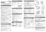
Name/Address/Phone No.
From the date of purchase
In this manual, the degree of hazard arising from actions such as improper operation is separated into the 3 levels “Danger,”
“Warning,” and “Caution.” In addition, instructions that must be followed for safe and proper use of this product as well as
practices that must be maintained are marked with a “Confirmation” heading. Please read and become familiar with these
sections.
Confirmation
●Be sure to follow all instructions in this manual to ensure safe installation and operation of the product.
●When the negative (-) battery terminal is disconnected, equipment such as clocks and audio components having
internal memory may lose their memory data. Follow the operation manual of each component to reset data after
installation of this product.
●After installation is complete, return this operation manual and the package to the customer along with the warranty.
●If car navigation system or car television is installed in vehicle, gauges and wires of this product need to be kept as
far away as possible from the wiring and installing positions of car navigation system or car television. Failure to do
so may result in interference of television display(VHF).
About Installation and Operation(for customer and installation personnel)
Warning
●Please have this product installed by the retail store or dealer where it was purchased. Installation by the customer
will void the warranty.
●Do not disassemble or modify this product. Such actions can not only damage or destroy the product but will also
void the warranty.
●In order to ensure safe driving, check the information on the gauge only for short periods of time. Looking at the
display for long periods of time could distract adequate attention from the road and result in an accident.
●Discontinue use of this product if nothing is displayed, water gets into the unit, or smoke or a strange odor comes
from the unit. If such a condition occurs, contact the sales outlet or installation personnel as soon as possible.
Continued use while the condition exists could result in an accident or fire.
●Do not operate during driving.
Caution
●On no event will Nippon Seiki Co., Ltd. be liable to you for any damages arising out of the use or inability to use the
product, even if Nippon Seiki Co., Ltd. has been advised of the possibility of such damage.
●Do not pull the wires out of connectors forcefully. The connectors may be broken and the wires may be cut. When
pulling out the wires, press the lock firmly and unclip the locks of connectors.
Confirmation
●This product cannot be linked to the Defi-Link System.
●The RPM of this product are for reference purposes only. Please drive according to the indication of vehicle's
originally equipped instruments.
●This product can be used only on 1, 2, 3, 4, 5, 6, and 8 cylinder vehicles with 4 cycle engine. Refer to the Product
Specifications. Engine revolution signal of diesel vehicles cannot be displayed.
CUT HERE
Main Features(for customer)
Power supply & tachometer signal wire
PDF07102H
Φ80(3 1/8") Mounting band set
(Mounting band x1, Mounting rubber x1)
PDF07103G
Φ80(3 1/8") Mounting bracket set
(Mounting bracket x1、M6 bolt x2, Spring lock washer x2,
Washer x2, Spacer x1, Tapping screw x2)
PDF07104G
Φ80(3 1/8") Regular Position Bezel
PDF07105G
Fuse for Power supply wire(1A) 2pcs
PDF07113G
Gauge
Illumination color (gauge dial & switch unit)
DF07401
0 - 9000RPM
White
DF07402
0 - 9000RPM
Amber Red
DF07403
0 - 9000RPM
BF Blue
DF07501
0 - 11000RPM
White
DF07502
0 - 11000RPM
Amber Red
DF07503
0 - 11000RPM
BF Blue
Part Number
Display Range
Illumination color (gauge dial & switch unit)
DF07101
0 - 9000RPM
Racer Gauge Blue
DF07201
0 - 11000RPM
Racer Gauge Blue
Blue Racer Gauge Tachometer
Connector for indicator
DC10V to 15V(For 12V vehicles)
Current Consumption
+B (red) line
MAX 0.4A (Dark current 0mA)
IGN (orange) line
MAX 0.4A
Applicable Number of Cylinders 1・2・3・4・5・6・8
Applicable Engine Speed Pulse Engine speed input 1(blue) <V1> 4.0V and above <V2> 0∼1.5V 【Graph1】
[※1]Refer to graphs below. Engine speed input 2(light blue) <V1> 1.5∼4.0V <V2> 0∼1.0V 【Graph2】
Refer to the Lineup section.
Display Range
Refer to the Dimensions section.
Dimensions
820g, 1.8lb(including gauge, switch unit, wires, package)
Gross Weight
[※1]The wave form of the engine speed signal should meet the requirements of Graph1 or Graph2.
【Graph1】 Engine speed input 1
(Use blue wire)
Volt
4.0V and
above
0∼1.5V
【Graph2】 Engine speed input 2
(Use light blue wire)
Volt
1.5V∼4.0V
0∼1V
Time
Time
Regular Position Bezel is a ring to fit onto the gauge front. The ▼ mark can be used as an indicator
of warning or shift-up in addition to the warning LED and the external indicator. By setting the ▼
mark at idling engine speed, you can notice the slight difference of your vehicle.
Installation(for customer and installation personnel)
Connector for switch unit
30.1(1.19")
58(2.29")
Connector for power supply & tachometer signal wire
Mounting Bracket
Switch Unit
31.4(1.24")
Caution
●Do not pull the wires out of connectors forcefully. The connectors
may be broken and the wires may be cut. When pulling out the
wires, press the lock firmly and unclip the locks of connectors.
15.7(0.62")
27(1.06")
▲switch
23.7(0.93")
Indicator
78(3.07")
50(1.97")
29.7(1.18")
Wire 20cm(7.8")
The indicator is exclusive to this tachometer.
Cannot be connected to other products.
Design of dial plate
BF Tachometer
●Carefully read the "Before Installation" and "About Installation and Operation" sections of the manual concerning
installation and operation. Then install the product properly and safely. Installation in an unsuitable location or
improper installation can result in the product falling from its position or damage to the vehicle.
●Take care not to scratch the gauge or vehicle by hitting or glinding the parts.
30(1.18")
This figure is printed on the
package at full scale. Cut and
use it to locate the mounting
bracket and position the screws.
Blue Racer Gauge Tachometer
STEP1 Wiring power supply & tachometer signal wire
1) Disconnect negative (−) battery cable of the vehicle.
2) Wire the power supply & tachometer signal wire as shown in the following figure.
Power supply & tachometer signal wire(2.2m, 7.2ft)
Fuse 1A
Red: Battery(To 12V battery wire)
Black: GND (To ground, negative battery terminal)
Orange: IGN (To 12V wire when ignition is on)
White: +ILM (To 12V wire when small light is on)
Blue: Engine speed input 1
6P
(Connect if the wave form of the engine speed signal is conformed with the graph1 of specification.)
Light blue: Engine speed input 2
(Connect if the wave form of the engine speed signal is conformed with the graph2 of specification.)
※Connect either blue wire or light blue wire referring to the specification of this manual and the service manual for
your vehicle.
※Insulate the unconnected wire(either blue wire or light blue wire).
※In case any other Defi-Link products are already installed in the vehicle, supply power from the same source as the
Defi-Link products to perform the opening and closing mode at the same time. If the power is supplied from the
different source from the others, gauges may not perform the opening and closing mode at the same time.
3) Reconnect negative (−) battery cable of the vehicle.
STEP2 Wiring check
ILM (white) line
MAX 2mA
Operational Temperature Range −20 to +60℃, −4 to +140゜F (under 80% relative humidity)
Storage Temperature Range −40 to +80℃, −40 to +176゜F (under 80% relative humidity)
A hole for power supply & tachometer signal wire
Regular Position Bezel is removable from the gauge. To change the position of the ▼ mark, remove
it once and then attach it again.
Product Specifications(for customer and installation personnel)
Power Supply Voltage
power supply &
tachometer
signal wire
Warning
PEAK LED(Blue)
Warning LED(Red)
Lineup(for customer)
Display Range
Storage space for
switch unit wire
▼Regular Position Bezel
9.9(0.39")
▼switch
Part Number
Switch
unit wire
Dimensions in mm(inches) and part names
Wire 45cm(1.48ft)
BF Tachometer
Indicator wire
φ80(3.15")
●Stepping motor "STS26A"
Maximum angle of deflective 270°(full sweep) is controlled by the microcomputer up to 4600 division
(0.057°each) to provide high precision in the accuracy of information generated.
The stepping motor is sufficient for quick response of all sorts of professional motorsports.
●LED illumination
The gauge dial is invisible while the ignition switch is off. Once the ignition switch is turned on, a clear
display appears by colored LED illumination.
The gauge dial illumination and the red emitting needle pointer provide high visibility.
●Opening and closing modes
The gauge dial and the needle pointer performs opening and closing modes interlocked with turning
ON/OFF of the ignition.
●Adjustable brightness
There are 5 stages of brightness for the daytime and 6 stages for the nighttime. The brightness can be
decreased/increased with the vehicle lights switched on/off.
●Dual warnings of light and buzzer
Two customer-defined warning RPMs can be set. When the RPMs are exceeded, the warning LED
blinks/lights up and the warning buzzer sounds.
●Exclusive large-sized indicator
The exclusive large-sized indicator which lights in green and red enhances the visibility of warnings in
addition to the warning LED in the gauge.
●Peak memory function
The maximum RPM during driving can be stored and checked later.
●Detachable switch unit
The large-sized switch unit with light is fixable on the gauge and is also detachable.
●Exclusive mounting band and back case
The gauge is clinched by using the exclusive mounting band and back case. Wires can be stored in
the back case neatly.
●Integrated rev adapter
By having the Defi rev adapter built-in, the tachometer works on vehicles with DIS (Distributor-less
Ignition System) which engine speed signals cannot be picked up due to connection vehicle control
units with serial communication.
Holes for indicator wire or switch unit wire
A hole for power supply & tachometer
signal wire
PDF07101G
44(1.73")
Caution
●This product is designed for use on 12V vehicles. Do not install this product on vehicles with 24V
systems.
●Insulate any unused wires. If any wires or connectors loosen during installation, please make
sure they are correctly reattached.
●Dropping any of the components of this product will result in damage to the product.
24V
●Excessive force on switches/terminals may result in damage to the product.
●Use only the wires provided. If additional wires are required, use the same of quality and gauge wire as is provided
with the kit.
●Do not attach wires on the body of the vehicle or engine parts as this may result in damage to the product.
●Install wires away from ignition and also radio signal frequency interference as this could cause the gauges to
malfunction.
●Do not place wires near the engine, exhaust pipe or turbine. It may result in damage or fusion of wires.
●Wear gloves to avoid burns when soldering and cuts when working with wiring.
●Make sure the waterproof processing is done when diverging wires in the engine compartment.
●Do not pull the wires out of connectors forcefully. The connectors may be
broken and the wires may be cut. When pulling out the wires, press the
lock firmly and unclip the locks of connectors.
●Do not install gauges in dashboard on passenger's side in case an air bag
is not equipped on the passenger's side. It doesn't meet vehicle safety
standards.
69.2(2.72")
Part Number
φ76.6(3.02")
Warning
●Carefully consider the installation location and driver's operation of the product before
installation. Do not install the product where it interrupts driving and the safety deices of vehicle.
Be sure not to install the unit where it could fall. Improper installation or operation could cause
the product to fall and damage the vehicle or cause serious danger by impeding driving.
●Do not disassemble or modify this product. Such actions can not only damage or destroy the
disassemble/
product but will also void the warranty.
modify
●Do not perform installation of this product immediately after the engine has been switched off.
The engine and exhaust system are extremely hot at this time and can cause burns if touched.
●Ensure that the wiring of this product does not have an adverse impact on the other wiring of the vehicle. Any
controlling devices or other electronic components of the vehicle could be damaged.
●Please keep children and infants away from the installation area. Children may swallow small parts or be injured in
other ways.
Part Name
Φ80(3 1/8") Back case set
(Back case x1, Buffer x1)
φ86.8(3.42")
●Ensure that the vehicle will remain stationary and turn off the engine before installing this product. Failure to do so
could result in a fire, and could make the vehicle move during installation.
●Remove the key from the ignition and disconnect the negative (-) battery terminal prior to installation of this product.
Failure to do so could result in a fire caused by an electrical short circuit.
●Take care not to install this product in a way that interferes with safety equipment such as seat belts and air bag
systems or vehicle operation equipment such as engine controls, steering wheel or brake systems. Interference
with normal operation of the vehicle can result in an accident or fire.
●Solder or use a solderless connector for wiring connections and make sure connections are insulated. In areas
where there could be tension or sudden impacts on the wiring, safeguard the wiring with corrugated tubing or other
shock absorbent material. Accidental shorts can cause fires.
●The ignition-switched +12V(IGN) line must be connected to the vehicle's ignition-switched wire with a fuse of 30A or
less. High-capacity fuse(more than 30A) will not blowout even with an abnormal current flow and may cause fire.
●Use a fuse of regulated capacity when the fuse of the power wire is changed. Using a fuse that exceeds regulated
capacity may cause fire.
34.2(1.35")
The mounting band is movable 4mm up and down.
φ32.2(1.27")
Danger
⑮Washer
⑯Spacer
⑰Buffer
⑱Double sided tape
⑲Tapping screw
⑳Solderless connector
50.6(1.99")
Indicates an instruction that must be performed or practice that must be maintained.
1
1
1
1
1
1
1
1
2
2
2
1
1
1
2
5
26.7(1.05")
Caution
Indicates a conceivable source of personal injury or damage to equipment if the product is
improperly operated.
1 year
∼
V2
Indicates the possibility of death or serious injury if the product is mishandled.
V1
Warning
’
⑤Mounting band
⑥Mounting rubber
⑦Power supply & tachometer signal wire 2.2m, 7.2ft
⑧Indicator(wire 20cm, 7.8in)
⑨Operation manual
⑩Terms and Conditions
Defi Business Division
190-1 Fujihashi 1-chome, Nagaoka-shi, Niigata 940-2141 JAPAN
E-mail: [email protected]
URL: http://www.defi-shop.com/
V2
Indicates the imminent dangerous situation of death or serious injury if the product is mishandled.
•
⑪Mounting bracket
⑫Attachment for switch unit
⑬M6 bolt
⑭Spring lock washer
Optional Parts(for customer)
V1
Danger
•
1
1 1
1
35°
Warranty Period
①Gauge
②Switch unit(wire 45cm, 1.48ft)
③Regular Position Bezel
④Back case
φ91.8(3.61")
Shop:
Quantity
30°
Name/Address
Part Name
")
Customer:
Quantity
116(4.55")
Part Name
'08.06-2
Before Installation(for installation personnel)
Confirmation
Lot. No.
▼Regular Position Bezel
45
1.
URL http://www.defi-shop.com/
76.5(3.01")
The following parts are included with this product. Confirm that all parts are present before installing the product. In
addition, these parts are sold separately for part replacement. Contact your retailer for further information.
NOTE: A Japanese operation manual, a wiring manual, and a questionnaire card are included other than the parts
listed below. They are effective only in Japan.
(
.9
This product is an additional tachometer. When installing and operating this product, be sure to read the
cautionary items of this operation manual as well as those given in the operation manual for the vehicle in
which this product will be installed. Please obtain a full understanding of the cautionary items and use the
product accordingly.
In the event that this product (or the vehicle in which it is installed) is lent to or transferred to another
person, please be sure this operation manual accompanies the product.
DF07
Product No.
92.1(3.63")
36
DF07401,DF07402,DF07403,
DF07501,DF07502,DF07503
DF07101,DF07201
* Refer to Terms and Conditions
* Do not peel the labels sticked on the manual and the backside of the gauge.
41.6(1.64")
BF Tachometer &
Blue Racer Gauge Tachometer
Operation Manual
Assembling example
Parts List(for customer and installation personnel)
Warranty
PEAK LED(Blue)
Warning LED(Red)
PEAK LED(Blue)
Warning LED(Red)
1) Connect the power supply & tachometer signal wire to the back side of the gauge.
2) Turn the key in the ignition. Then check the gauge illumination is lighted and the gauge pointer moves. (Refer to the
opening mode of Operation section.)
※The gauge is assembled and clamped down in the next step. During assembling, the gauge illumination is not
lighted. Check the zero point at this stage. The gauge pointer may not be in the proper position when you purchase.
Once the power is turned on, it points back to the zero point.
3) Turn on the vehicle lights and make sure the gauge illumination is dimmed.
4) Turn the ignition key off. Then check the gauge pointer points back to the zero point and the gauge illumination is
turned off. (Refer to the ending mode of Operation section.)
5) To fix the gauge on a vehicle in the next step, disconnect the power supply & tachometer signal wire.
See reverse side: Fix the gauge on a vehicle in the STEP3.⇒
Installation(for customer and installation personnel)
【Figure1】 Gauge assembly
Install the gauge as shown in the following procedures and figures.
④Back case
Upper switch(▲/SET-2/PEAK) → ▲switch or
Lower switch(▼/SET-1/PEAK RESET) → ▼switch or
⑤Mounting band
⑧Indicator
⑱Double sided tape
⑮Washer
⑰Buffer
⑭Spring lock washer
①Gauge
⑬M6 bolt
⑯Spacer
Returns to real mode
Warning setup
To Set up the RPMs of warning. Two points(SET1 and SET2) can be set.
Buzzer setup
To Set up the buzzer ON/OFF of warning SET2.
Opening/
When the ignition is turned on/off, the opening and closing motion is played by using the illu-
Closing mode
Real mode
In real mode
unused
Peak mode
Displays the maximum RPM recorded during driving. The maximum RPM is always record-
dicator.
ba
ed in the real and peak modes. It can be reset.
ck
ba
ck
Controls the brightness of the gauge illumination. There are 5 stages of brightness for the
on
fr
t
⑱Double sided tape
The following is the list of operations with switches. In the setup mode and the warning setup mode, the mode changes to
the real mode when any switch is not pressed for more than 5 seconds.
5) Fit the attachment for switch unit and indicator into the mounting band. And then fit
the gauge into the mounting band. Locate the switch unit and the indicator roughly
at this stage. The switch unit and the indicator can be positioned in the range which
they do not touch the mounting bracket and bolts.【Figure4】【Figure5】
※Do not take hands off from the gauge so as the gauge does not fall down.
※If the switch unit is fixed to another place other than the gauge, do not fix/use the
attachment for switch unit to the mounting band.
Two warning RPMs can be set at SET1 and SET2. Set the SET2 RPM higher than the SET1 RPM. The factory setting is
at 6000rpm(SET1) and 7000rpm(SET2). Change the RPMs as you like.
※Even if the battery is disconnected, the setting is not cleared.
【A】Warning setup mode − SET1
In the real mode, the mode changes to the warning setup mode SET1 if ▼switch is pressed for more
than 2 seconds. In the warning setup mode SET1, the warning LED blinks as follows:
Real
mode
Press 2 switches at the same
time for more than 2 seconds.
Press ▼ switch for
more than 2 seconds.
Buzzer
on/off of
Warning
SET2
Setting of
number of
cylinders
5sec later Returns to the real mode
Press ▲ switch for
more than 2 seconds.
Warning setup mode
SET1
Setup mode
Operation
after the
mode is
changed
Warning setup mode
SET2
Press ▲ switch.
Peak mode
Raise setting Lower setting Raise setting Lower setting Returns to
real mode
To raise fast- To lower fast- To raise fast- To lower faster, push long. er, push long. er, push long. er, push long.
Returns to the real mode
Press
▼ switch.
Dimmer
control
Peak RPM
Brightness
is reset and changes every
returns to time switch is
real mode.
pressed.
Returns to the real mode
LED blinking
press
long
raise
Confirmation
●Be sure to make preparatory settings. The unit will not operate properly without the settings being made.
●Set up while the vehicle is stationary.
lower
In the real mode, the mode changed to the setup mode by pressing ▲switch and ▼switch at the same
time for more than 2 seconds. In the setup mode, the peak and warning LEDs in the gauge blinks alternately. And the gauge pointer points the number of cylinders. The buzzer bleeps. Set up the number
of cylinders and the buzzer on/off in the setup mode. The mode returns to the real mode automatically
when any switch is not pressed for more than 5 seconds.
Positioning of gauge / fixing of mounting bracket
For inner side of back case
For bottom of bracket
If the warning SET1 RPM is set higher than the SET2 RPM:
→The warning SET2 RPM is changed to the same RPM as the SET1 RPM.
Ex) If the SET2 RPM is set at 6000rpm, it is changed to 7000rpm when the SET1 RPM is changed to 7000rpm.
【B】Warning setup mode − SET2
In the real mode, the mode changes to the warning setup mode SET2 if ▲switch is pressed for more
than 2 seconds. In the warning setup mode SET2, the warning LED blinks as follows:
6) Identify the position of the mounting bracket with the gauge fitted into the mounting
band. Mark the shape of the mounting bracket and the position of the screw holes.
The figure printed on the package can be used to position the screw holes.
※To check that there is enough space for installation, identify the gauge position
with the gauge, switch unit, and indicator fitted into the mounting band.
※When setting the gauge angle, take care not to scratch by hitting the gauge to the
mounting bracket.
7) Disassemble the mounting band from the mounting bracket, and disassemble the
gauge, attachment for switch unit, and indicator from the mounting band.
8) Attach double sided tapes on the bottom of the mounting bracket.【Figure1】【Figure6】
9) Fix the mounting bracket on the gauge installing position by using the tapping
screws.
Reassembling gauge / fixing gauge to mounting bracket
10) Fit the attachment for switch unit, indicator, and gauge into the mounting band again.
【Figure7】Connect indicator wire
Take notice that the angle of the switch unit and the indicator cannot be changed
Pass wires
through
while the bolts are fastened.
holes from
※If the switch unit is fixed to another place other than the gauge, do not fix/use the
back side
attachment for switch unit to the mounting band.
11) Attach the double sided tape on the back side of the gauge.【Figure1】【Figure6】
12) Pass the indicator wire and switch unit wire through the holes of the back case from
the outside. Connect the indicator wire to the connector on the gauge. Refer to part
【Figure8】Put wires in back case / Connect
names section.【Figure7】
switch unit wire and power supply wire
13) Put the back case on the gauge. Position the hole for the power supply & tachometer signal wire to the gauge connector for it. Refer to part names section. The indicator wire can be stored in the back space in the back case.
14) Connect the switch unit wire to the connector on the back side of the gauge. The indicator wire can be stored in the storage space in the back case neatly.【Figure8】
15) Connect the power supply & tachometer signal wire to the connector on the back
【Figure9】Fasten bolts with hexagonal
side of the gauge.【Figure8】
wrench
press long
LED blinking
press
long
raise
Time
Peak LED
Warning LED
Buzzer
Bleep (short beeps)
lower
The pointer points the number of cylinders.
【A】Setup number of cylinders
In the setup mode, the setup of the number of cylinders changes every time ▼switch is pressed(4→3→
2→1→8→6→5→4→・・・(repeat). Match the number on the gauge dial and the number of cylinders of
your vehicle.
The mode returns to the real mode automatically when any switch is not pressed for more than 5 seconds.
【B】Setup buzzer
Set whether to turn the buzzer on or off when warning SET2 is exceeded.
18) Fit the regular position bezel onto the gauge with setting the ▼ mark at the position
you like.
STEP4 Final check and setup
1) Make sure the gauge is fixed on the installing position firmly. Then turn the vehicle engine on and off and check the
movement of the pointer, illumination of the gauge, and engine speed signal input.
※Make sure there are no tools on the vehicle floor and that the vehicle surrounding is safe before turning on the engine.
2) Go on to the operation section and set up the number of cylinders, and so on. Give this manual to the customer if
he/she sets up by himself/herself.
Warning
●If operation of the product seems unusual, inspect the product to confirm that there is no malfunction. If an
operational problem has occurred, it could result in an accident.
Possible Cause
Corrective Action
○Does not operate.
○Power is not supplied.
○Wiring of the power supply wire is improp- ○Check wirings of +B, IGN, GND as per instructions in this manual.
er.
○Check the lock of the solderless connectors.
○The locks of the solderless connectors
are not locked tightly.
○The RPM is not displayed
correctly.
○Wiring of the tachometer signal or the rev ○Check wiring as per instructions in this manual.
adapter is wrong.
○Setting of the number of cylinders is
○Check the number of cylinders as per instructions
wrong.
in this manual.
○Does not carry out the clos- ○The battery wiring is wrong.
○The fuse of the power supply wire is
ing mode.
blown out.
○Check wiring of +B as per instructions in this
manual.
○Make sure the wiring is not touched on the vehicle body and then change the fuse.
○Check the solderless connector of battery wiring.
○The illumination brightness
doesn't change by turning
on/off the vehicle illumination.
○Check if the illumination is in the brightest level of
nighttime mode and press ▼switch.
○Check wiring of ILM as per instructions in this
manual.
○Check the lock of the solderless connectors.
○The illumination is in the brightest level of
nighttime mode.
○Wiring of the power supply wire is improper.
○Check if the difference is up to 10%. This product is designed emphasizing accuracy and
should have little error margin. If the difference
is bigger than 10%, check the setup of the number of cylinders.
To raise the set RPM of the warning, press ▲switch. Every time ▲switch is pressed, the set RPM is
raised in degree. If ▲switch is pressed long, the set RPM is raised faster. To lower the set RPM of the
warning, press ▼switch. Every time ▼switch is pressed, the set RPM is lowered in degree. If ▼switch is
pressed long, the set RPM is lowered faster.
○The warning LED lights up
at the different RPMs than
set RPMs.
○The warning set1 RPM is set higher than ○When the warning set1 RPM is set at the higher
the warning set2 RPM or the warning
RPM than the warning set2 RPM or when the
set2 RPM is set lower than the warning
warning set2 RPM is set at the lower RPM than
set1 RPM.
the warning set1 RPM, set RPMs are changed
automatically. Refer to Operation section.
The mode returns to the real mode automatically when any switch is not pressed for more than 5 seconds.
※The range of the warning RPM which can be set is from 500rpm is to the maximum scale RPM.
※Set the higher RPM than the warning SET1 RPM.
○The needle pointer is not
downward before the electricity is turned on.
○The pointer moves during transfer.
If the warning SET2 RPM is set lower than the SET1 RPM:
→The warning SET1 RPM is changed to the same RPM as the SET2 RPM.
Ex) If the SET1 RPM is set at 7000rpm, it is changed to 6000rpm when the SET2 RPM is changed to 6000rpm.
4.Motion mode
①Opening and closing mode
The gauge performs the opening mode when the ignition key is turned on and performs the closing mode when the ignition
key is turned off.
※The brightness is at the maximum level during the opening mode regardless of the dimmer control setup.
※In case any other Defi-Link products are already installed in the vehicle, supply power from the same source as the DefiLink products to perform the opening and closing mode at the same time. If the power is supplied from the different
source from the others, gauges may not perform the opening and closing mode at the same time.
②Real mode
The gauge pointer points at the RPM in real time. The maximum RPM is recorded during this mode.
If the buzzer is set on, it feeps (a long beep) when the RPM exceeds the warning SET2 in the real
mode. If the buzzer is set off, it does not sound.
In the real mode, when the RPM exceeds the set warning RPMs, the warning LED and the indicator light up/blink as follows.
※The buzzer sounds when switches are pressed. It cannot be turned off.
■ ■→■→■→■→■
○The RPM gauge indicates is ○Originally equipped gauges commonly
a little lower than that of
indicate up to 10% higher RPM.
originally equipped gauge.
Warning LED
③Warning mode
【Scene A】When the RPM is lower than the warning SET1 RPM
The warning LED is off. The buzzer is off. The indicator is off.
【Scene B】When the RPM is higher than the warning SET1 RPM
The warning LED is on. The buzzer is off. The indicator is on in green.
【Scene C】When the RPM is higher than the warning SET2 RPM
The warning LED blinks. The buzzer feeps (a long beep). The indicator is on in red.
※The buzzer does not sound if the buzzer is set off in the setup mode.
16) Fit the mounting band with the gauge in the mounting bracket by using a spacer,
bolts, washer, and spring lock washer.
※Depending on the installing space, it may difficult to fit the gauge. Do not pull
wires forcefully and take notice not to hit the vehicle by parts.
17) Fasten the bolts with a hexagonal wrench (Allen key) firmly.【Figure9】
Time
In the setup mode, the buzzer is turned on/off by pressing ▲switch. If the buzzer is set on, it bleeps
(short beeps) in time with blinking of the peak and warning LEDs. If the buzzer is set off, it does not
sound.
The mode returns to the real mode automatically when any switch is not pressed for more than 5 seconds.
Darker
※In addition to a general inspection of the product, use the following table to confirm proper operation of the unit. If the
operational problem does not appear in the following table, contact the installation personnel.
To raise the set RPM of the warning, press ▲switch. Every time ▲switch is pressed, the set RPM is
raised in degree. If ▲switch is pressed long, the set RPM is raised faster. To lower the set RPM of the
warning, press ▼switch. Every time ▼switch is pressed, the set RPM is lowered in degree. If ▼switch is
pressed long, the set RPM is lowered faster.
LED blinking
Brighter
■→■→■→■→■
Trouble Shooting(for customer and installation personnel)
Condition
①Setup mode
Set up the number of cylinders and buzzer. The factory setting of the number of cylinders is 4. If the gauge is installed in
a vehicle which the number of cylinders is not 4, change the number as follows. The factory setting of the buzzer is ON.
※Even if the battery is disconnected, the setting is not cleared.
Time
Warning LED
The mode returns to the real mode automatically when any switch is not pressed for more than 5 seconds.
※The range of the warning RPM which can be set is from 500rpm is to the maximum scale RPM.
※Set the lower RPM than the warning SET2 RPM.
3. Setup
【Figure5】Range of fitting of switch unit
and indicator
Daytime
(vehicle lights off)
Nighttime
(vehicle lights on)
②Warning setup mode
2. Switch operation list
3) Fix the mounting band to the mounting bracket temporarily with the spacer, bolts,
washers, and spring lock washers. Tighten bolts loosely by hands. Do not use a
hexagonal wrench (Allen key) at this stage.【Figure3】
4) Insert the switch unit into the attachment for switch unit.【Figure1】
※If the switch unit is fixed to another place other than the gauge, do not use the attachment for switch unit.
Brightness level
vehicle lights switched on/off.
1) Attach the buffer around the gauge.【Figure1】
※Do not touch on the front face of the gauge so as not to put fingerprints.
2) Fit the mounting rubber inside of the mounting band.【Figure2】
【Figure6】How to use double sided tape
In the real mode, the brightness of the gauge illumination is controlled by pressing ▼switch. There are
5 stages for the daytime and 6 stages for the nighttime. The brightness can be decreased/increased
with the vehicle lights switched on/off.
※Even if the battery is disconnected, the set level is not cleared.
※The brightness level does not change even if ▲switch is pressed. The mode changes to the peak mode.
daytime and 6 stages for the nighttime. The brightness can be decreased/increased with the
Temporal gauge assembling
【Figure4】Fitting indicator, attachment
for switch unit, and gauge in band
⑤Dimmer control
Informs the RPM exceeds the set warning RPMs by the warning LED, the buzzer, and the in-
⑪Mounting bracket
nt
②Switch unit
mination of the gauge and movement of the pointer.
Displays the RPM in real mode during driving and idling.
Warning mode
Dimmer control
o
fr
③Regular Position Bezel
Peak LED blinks and recorded maximum RPM is reset.
Then pointer points at 0rpm and mode returns to real mode.
Number of cylinder setup To Set up the number of cylinders according to your vehicle
⑲Tapping screw
⑫Attachment
for switch unit
In the real mode, the peak LED lights up and the mode changes to the peak mode by pressing ▲switch.
The recorded maximum(peak) RPM is displayed during the peak mode. Every time the maximum RPM
is updated, it is recorded. The peak mode returns to the real mode by pressing ▲switch again.
In the peak mode, the peak LED blinks and the maximum RPM is reset by pressing ▲switch. Then the
peak mode returns to the real mode.
※Even if the battery is disconnected, the recoded maximum RPM is not cleared.
To peak mode
1.Function
⑥Mounting rubber
【Figure3】Fixing band to bracket
In real mode
Two switches are expressed in this section as follows.
STEP3 Installing gauge
【Figure2】Fitting rubber in band
④Peak mode
Operation(for customer and installation personnel)
Warning SET1
Lower
Warning SET2
Engine speed
Higher
Scene
【Scene A】
【Scene B】
Warning LED
Off
On
【Scene C】
Blink
Buzzer
Off
Off
Feep(a long beep)
Indicator
Off
On(green)
On(red)
○It is an inherent property of the stepping motor.
The pointer may move when a slight impact is
made to the gauge. Check if it operates normally
by turning on and off the electricity and the pointer
points zero after the ignition is turned off.