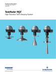
1
THE XHR-300 SERIES
Operating and Service Manual
Series includes all variants of XHR-300/301/310/311
Issue B
September 2015
1
TABLE OF CONTENTS
1. Description ............................................................................................................................. 3
2. Installation and Wiring ........................................................................................................... 4
2.1 Enclosure (Junction Box) .......................................................................................... 4
2.2 Regulator.................................................................................................................. 4
2.3 Mounting ................................................................................................................. 4
2.4 Wiring Instructions .................................................................................................. 4
3. Operation ............................................................................................................................... 5
3.1 Adjusting the Regulator ........................................................................................... 5
3.2 Adjusting the Temperature...................................................................................... 5
4. Special Conditions for Safe Use ............................................................................................. 6
5. Hazardous Location Usage ..................................................................................................... 6
5.1 Marking .................................................................................................................... 6
6. Servicing and Maintenance .................................................................................................... 7
6.1. Servicing the XHR-300............................................................................................. 8
6.1.1. Accessing the Main Valve Assembly ........................................................ 8
6.1.2. Adjusting the Set Point ............................................................................ 9
6.1.3. Figure 1 – Sectional View of the XHR-300 ............................................. 10
6.2. Servicing the XHR-311........................................................................................... 11
6.2.1. Accessing the Main Valve Assembly ...................................................... 11
6.2.3. Figure 2 – Sectional View of the XHR-311 ............................................. 12
7. Technical Data ...................................................................................................................... 13
8. Warranty Statement ............................................................................................................ 13
2
1. Description
The XHR-300 series comprises of the following models:
-
XHR-300 – Dual heated, diaphragm sensed pressure regulator (standard option)
XHR-310 – Dual heated, diaphragm sensed pressure regulator (disk seat option)
XHR-301 – Dual heated, piston sensed regulator (standard option)
XHR-311 – Dual heated, piston sensed regulator (disk seat option)
The maximum working pressures for each model are defined in the table below and are
determined both by the model and the seat material. The maximum outlet control range of
the diaphragm sensed and piston sensed options are 0-35 bar and 0-150 bar respectively.
Model
Seat Material
PCTFE
PEEK
XHR-300
210 bar
300 bar
XHR-310
300 bar
414 bar
XHR-301
210 bar
300 bar
XHR-311
300 bar
414 bar
Regulator housings are machined from 316 SS (stainless steel). This ensures maximum
protection against the media on which they will be used and the environment in which they
will be placed. The regulator can be used to regulate any gas or liquid that is compatible
with the materials of construction.
The electronics controlling the heat input to the regulator/manifold are installed within a
Cortem GUB flameproof enclosure. The electrical housing is of Aluminium Alloy
construction, with mounting lugs to provide a secure connection to the panel. The user
must ensure that media in contact with the regulator is compatible with these materials.
The enclosure has three cable entries of size M20 x 1.5 through which the electrical supply
can be made (ref. ‘Wiring Instructions’). The remaining entries must be sealed with ATEX
approved Blanking Plugs (supplied).
The models are fitted with two heat exchanging sheaths each enclosing a 100W cartridge
heater within. The media passes over the sheath on the inlet to the regulator for ‘pre-heat’,
and after the pressure reduction within the regulator, then passes the second sheath on the
outlet for ‘secondary heat’. An adjustable pot within the electronics controls the amount of
heat output via a burst-firing controller within the circuit board. Each heater cartridge has
an independent switch which can be used to isolate the power to either channel. The
cartridges are wired independently and fitted with type J sensors, which monitor the
temperature to each unit separately and keep the regulator within its T3 temperature class.
The XHR-300 series should not be exposed to any vibrations or impacts, and should be
securely fastened in accordance to the Installation Instructions below, and should be limited
to the vibration limits stated in the Section 7, Technical Data.
Any pressure gauges used on the regulator must be designed as ‘Full Safety Pattern’ to
BS1780, ANSI B40-1 and EN837-1.
3
2. Installation and Wiring
Before installation, check the nameplate (where applicable), model number reference and
regulator label affixed to the enclosure and ensure that the voltage type and pressure range
complies with the installation requirements.
*Note: Installation of the XHR-300 series of heated regulators should be in accordance with
EN 60079-14
2.1 Enclosure (Junction Box)
The enclosure is of series GUB manufactured by Cortem. The enclosure is marked Ex II 2 Gb
/ Ex d IIC Gb (equipment group II, cat 2) in accordance with certificate CESI 01 ATEX 034U
and IECEx CES 14.0012U. The enclosure has an ingress protection level IP 66.
2.2 Regulator
The pressure regulator is supplied with 1/4” NPT connections for both the inlet and outlet
ports. Connections for gauges are available and will be 1/4” NPT as standard. The maximum
supply pressure to the regulator should not exceed the maximum pressure indicated on the
regulator label. The pipe work and gauges should be sealed with the regulator using PTFE
tape.
*Note: Pressure Tech do not recommend sealant compound for pipe work connections.
2.3 Mounting
The whole assembly should be securely fastened to a back plate or panel using the corner
holes in the junction box. For added support, the top of the regulator can be panel mounted
around the bonnet, using the optional panel nut (PT C 024).
*Note: The panel nut alone should not support the regulator, i.e. with the box left
freestanding.
2.4 Wiring Instructions
Ensure that no electrical power is supplied during maintenance, installation or servicing this
product. The power supply to the junction box will require a certified cable gland to be used.
An external earth point is located on the enclosure.
CAUTION: Refer to accompanying documents
There are three cable gland entries on the enclosure, each connection is M20 x 1.5 – 6H
Use cable and cable entry devices suitable for 77°C
Feed the supply cable through the cable gland (not supplied) and secure the wires to the
terminal block ensuring the Live and Neutral are correctly orientated
(ref. Drawing No. PT-XHR-300-CIR-002)
*Note: Wiring should be made in accordance with BS7671 ‘Requirements for electrical
installations’.
4
3. Operation
3.1 Adjusting the Regulator
For the XHR-300 series of regulators, turning the hand wheel clockwise compresses the
spring, which in turn opens the main valve and allows the inlet pressure to pass through the
orifice until the outlet pressure is equivalent to the loading forces set by the compressed
spring.
3.2 Adjusting the Temperature
An adjustable potentiometer on the surface of the PCB controls the amount of heat output
via a burst firing controller. The cartridge is fitted with a type J sensor which monitors the
temperature to the unit. Should this sensor fail, or the wiring becomes disconnected, the
PCB will not apply power to the heater cartridge.
The adjustable pot is factory pre-set to its midpoint, but may need adjusting to increase or
decrease the heat requirements to the regulator. *This adjustment must be made when
there is no risk of explosion from the outside environment.
To adjust the setting:
i.
ii.
iii.
iv.
v.
5
Loosen the M4 grub screw and open the cover of the junction box.
Change the heater output by turning the pot on the circuit board clockwise to
increase, and anti-clockwise to decrease.
Due to the response time of heat transfer and thermal coefficients, the control
system will require about 5 to 10 minutes to stabilise. Therefore, it is
recommended that the heater is switched on before allowing the media to pass
through the regulator.
The following percentage turns around the potentiometer equate to an
approximate temperature value for the heater cartridges:
10% – 20°C
25% – 60°C
50% – 100°C
75% – 140°C
100% – 180°C
When the correct temperature setting is made, screw back the box cover and
secure grub screw.
4. Special Conditions for Safe Use
On non-venting regulators with pressure on the outlet, the hand wheel shall not be turned
anti-clockwise, in this case, pressure shall be reduced by venting downstream of the
regulator and turning the hand wheel simultaneously anti-clockwise.
The junction box should never be opened whilst there is a flammable gas atmosphere
present, or when there is a risk of explosion from the outside environment.
The user shall ensure that the equipment is appropriately connected to earth.
The equipment shall not be exposed to vibrations exceeding 5m/sec2
The equipment shall be protected from mechanical impact in service by location or suitable
guarding.
To prevent damage being caused to the regulator, which may result in an ignition risk, it is
the user’s responsibility to ensure the equipment is operated in accordance with the
manufacturer’s instructions and recommendations.
The equipment has flame paths which differ from those in IEC 60079-1:2014. The
manufacturer, Pressure Tech, shall be contacted for guidance when maintaining the flame
paths.
5. Hazardous Location Usage
The XHR-300 series of regulators have been certified under the ATEX directive 94/9/EC as
suitable for use in Group II, Category 2 gas environments, where the surface temperature
does not exceed 200°C (based on ambient temperature conditions of -40°C to +60°C) and is
flameproof to EN 60079-0 and EN 60079-1.
5.1 Marking
The marking of the equipment shall include the following:
Ex II 2 G T3
Ex db IIC GB T3
Ta = -40°C to +60°C
6
6. Servicing and Maintenance
The XHR series comprises of both diaphragm and piston sensed options for pressure control.
Each can be fitted with one of two options of main valve assembly (MVA). The combinations
of such result in the four models of heated regulator described in section 1. Two examples
of which are used in this section with an intent of covering most options available.
Servicing and maintenance work on the XHR-300 series should only be performed after fully
reading and understanding the Operating and Servicing Manual. Due to the typical nature of
the gases the regulator will be used on, the operator should not endanger himself/herself or
others by working on this regulator without prior knowledge on the Health and Safety
concerns relating to handling of technical gases. Any uncertainty should be clarified with
Pressure Tech before working on the regulator.
Repairs to the regulator should be performed in accordance with BS EN 60079-17 and BS EN
60079-19 as applicable.
Pressure Tech Ltd recommends the use of Krytox GPL 205 during servicing.
IMPORTANT: Any failure within the electronics should result in the unit being returned to
Pressure Tech for evaluation and repair.
Prior to commencing service, please ensure that:
-
7
The equipment has been de-pressurised
The load spring has been de-compressed by turning the hand wheel / adjusting
screw fully anti-clockwise
Applications involving toxic, flammable or corrosive media have been fully purged
6.1. Servicing the XHR-300
*Note: fig 1 should be used as a reference for the following set of instructions
6.1.1. Accessing the Main Valve Assembly
To access the Main Valve Assembly (MVA):
i.
ii.
iii.
iv.
v.
vi.
vii.
viii.
ix.
x.
xi.
Secure the regulator body (3) in a vice* and loosen the Bonnet (15) from the
regulator body using a 47mm open ended torque wrench or equivalent ensuring
that the Hand Wheel (3) is fully wound anti clock wise (NOTE*)
*Where this is not possible it may be necessary to secure the enclosure. If the lid
of the enclosure is to be removed it is important to ensure that an explosive
atmosphere is not present before doing so.
Remove the Upper Spring Rest (11), 10mm Ball Bearing (9), Load Spring (20),
Diaphragm Washer (19), Lower Spring Rest (12) and Diaphragm (10) from the
assembly
The Seat Nut (6) can then be removed using a 12mm socket
Remove the Main Valve (4, 5) and Main Valve Spring (7) from the assembly
Visually inspect the seat nut (6) and soft seat (5) for damage under a microscope
Replace the Main Valve Spring (7) and Main Valve (4, 5) and place into the
Regulator Body (3)
Replace Seat Nut (6) fitted with new 5x1 mm O-ring (8) taking care not to
damage the sealing face against the tip of the valve
To ensure positive sealing, it is recommended that a new Diaphragm (10) is
placed centrally into Regulator Body (3) ensuring that the outermost
convolutions are facing towards the Bonnet (15)
Replace the 21x1 mm O-ring (21) on the Lower Spring Rest (12), insert into the
Diaphragm Washer (19) and place on top of the Diaphragm (10)
Place the Load Spring (20), Upper Spring Rest (11) and 10mm Ball Bearing (9) to
the assembly
Screw the Bonnet (15) onto the assembly and using a torque wrench with a
47mm open ended attachment, tighten to 160Nm
It is recommended that all parts in the repair kits are used. Any defect parts removed during
the service should be disposed of. Parts should be kept clean in line with media
requirements.
Following re-assembly of the regulator, pressure tests should be made to both the inlet and
outlet side of the regulator, to ensure there is no internal or external leakage across the
regulator.
To ensure that the main valve assembly has been correctly and effectively installed it may
be required to perform the appropriate seat leak test as per ANSI/FCI 70-2.
Should any assistance be required during a service please do not hesitate to contact the
office.
8
(NOTE*) It is not recommended (or necessary) to remove the Hand Wheel (18) during
service as this will affect the set point of the regulator. Should it be required to adjust the
set point please follow the instructions below:
6.1.2. Adjusting the Set Point
To adjust the set point:
i.
ii.
iii.
iv.
v.
vi.
vii.
viii.
ix.
x.
xi.
xii.
xiii.
xiv.
xv.
xvi.
9
Remove the Nameplate (17) and Cap (16) from the Hand Wheel (18) and loosen
the Lock Nut (14) such that the Hand Wheel is able to spin freely on the Adjusting
Screw (13)
Connect the correct fittings to the Inlet and Outlet ports of the regulator. Ensure
that any gauge ports are plugged or that the correct gauge is fitted
With the Regulator Body (3) securely fixed to the Heater Sheaths (5) apply the
Maximum Working Pressure (MWP) to the Inlet of the regulator
Connect the Outlet port to a calibrated pressure test gauge appropriate to the
required set pressure. As the regulator is non-venting, ensure that a ball/needle
valve is fitted to allow pressure to be relieved downstream of the regulator
Using a slotted screwdriver, turn the Adjusting Screw (13) clockwise until the
desired set point has been reached
Ensure repeatability by allowing flow through the regulator using the ball/needle
valve
With the outlet pressure set, screw the first Lock Nut (14) to the base of the
Adjusting Screw (13) against the Bonnet (15)
Position the Hand Wheel (18) onto the Lock Nut (14). Ensure that the Lock Nut
and Hand Wheel become engaged
Fasten the second Lock Nut (14) against the Hand Wheel (18) and gently begin to
tighten using a 13mm socket until it begins to secure itself
At this point, whilst holding the Hand Wheel (18) continue to tighten whilst
simultaneously turning slightly anti-clockwise to prevent it from locking against
the Bonnet (15)
Ensure that the Lock Nut (14) is sufficiently tightened, taking care not to adjust
the set point
Turning of the Hand Wheel (18) should now also turn the Adjusting Screw (13)
which will control the pressure
Turn the Hand Wheel (18) clockwise until it reaches its set point and check to
make sure that the desired outlet pressure is correct.
If the set point is not correct, repeat steps v. to xiii.
Reduce the pressure downstream by venting the pressure through ball/needle
valve and then turning the Hand Wheel (18) anti-clockwise until the regulator
closes
The Cap (16) and Nameplate (17) can now be placed into the Hand Wheel (18).
Ensure that the information stated on the Nameplate (17) is in accordance with
the set pressure of the regulator
6.1.3. Figure 1 – Sectional View of the XHR-300
(172.6)
(111.1)
Ø40
65
Ø60
Ø49
M33x1 - 6g
(116)
A
58
11
Ø52
A
1
23
55
(50.28)
ITEM
1
2
3
4
5
6
7
8
9
10
11
12
13
14
15
16
17
18
19
20
21
22
120
DETAIL C
SCALE 3 : 1
6
8
5
4
7
C
17
16
18
13
14
15
9
11
20
12
21
23
PARTS LIST
PART NUMBER
DESCRIPTION
PT-EHR-300-006
CORTEM BOX
PT-EHR-300-005-230
HEATER CARTRIDGE 230V
PT-EHR-300-N-SS
BODY - N PORTING - 1/4" NPT
PT-C-001-013
MAIN VALVE WITH SQUARE
PT-C-002-011
PCTFE SEAT
PT-C-007-002
SEAT Cv 0.06
PT-C-006-002
MAIN VALVE COMPRESSION SPRING
OR-0050-10
O' RING STD
BALL-010-SS-316
10MM BALL BEARING
PT-C-010-002
DIAPHRAGM
PT-C-017
UPPER SPRING REST
PT-C-018-002
BOTTOM SPRING REST
PT-C-019-003
ADJUSTING SCREW
PT-C-020
LOCKNUTS
PT-C-015
BONNET
NAMEPLATE CAP
FIT-CAP-4343092
NAMEPLATE
PT-C-022
PT-C-021
SMALL HANDWHEEL
PT-C-016
DIAPHRAGM WASHER
PT-C-011-009
LOAD SPRING
OR-0210-10
O' RING STD
FIT-03-08-BSP-BOND-SEAL 3/8" BSP BONDED SEAL
19
10
3
SECTION A-A
SCALE 1.5 : 1
5
2
3
22
© Copyright of Pressure Tech Ltd
10
6.2. Servicing the XHR-311
*Note: fig 2 should be used as a reference for the following set of instructions
6.2.1. Accessing the Main Valve Assembly
To access the Main Valve Assembly (MVA):
i.
ii.
iii.
iv.
v.
vi.
vii.
viii.
ix.
x.
xi.
xii.
xiii.
xiv.
Secure the regulator body (5) in a vice* and using a 47mm open ended torque
wrench or equivalent loosen and remove the Bonnet (21) from the Regulator Body
*Where this is not possible it may be necessary to secure the enclosure. If the lid of
the enclosure is to be removed it is important to ensure that an explosive
atmosphere is not present before doing so.
Remove the Upper Spring Rest (24), 10mm Ball Bearing (25) and Load Spring (20)
from the assembly
Lift the Lower Spring Rest (11) out of the assembly and then remove the sensor
assembly comprising of Sensor (14) and Sensor Holder (13) from the Body (5)
Using a 12mm socket, remove the Seat Retainer (6) and O-Ring (10) from the
Regulator Body (5)
Grip the main valve (7) (needle nose pliers may be useful) and lift out of the Body (5)
which will in turn bring out the Soft Seat Disk (8) and O-Ring (9)
The Main Valve Spring (11) can then be removed and replaced if required
Place new Main Valve (7) on to the Main valve Spring (11)
The Soft Seat Disk (8) can then be positioned into the Body (5) ensuring that the ORing groove is facing outwards then carefully position the O-Ring (9) into place (care
should be taken when positioning the seat disk over the main valve)
Replace the O-Ring (10) on the Seat Retainer (6) and screw the Seat Retainer into the
Body (5) and tighten with a 12mm socket
Replace the O-Ring (16) and Back Up ring (18) on the Sensor Holder (137) and
replace the O-Ring (15) and Back Up Rings (17) on the Sensor (19) - (*29 and *30 for
smaller 8mm sensor *28)
Place the Sensor (14) into the Sensor Holder (13) and position the assembly into the
Regulator Body (5)
Replace the O-Ring (19) on the Lower Spring Rest (12) and position into the Sensor
Holder (13)
Place the Load Spring (20), Upper Spring Rest (24) and 10mm Ball Bearing (25) to the
assembly and screw the bonnet (21) into position
Finally tighten the bonnet to 90 Nm with a 47mm open ended torque wrench
To ensure that the main valve assembly has been correctly and effectively installed it may
be required to perform the appropriate seat leak test as per ANSI/FCI 70-2.
11
6.2.3. Figure 2 – Sectional View of the XHR-311
(161.13)
28*
Ø40
M33x1 - 6g
27*
67
Ø60
Ø50.5
(123.2)
30*
A
* ALTERNATE
8mm SENSOR ASSEMBLY VIEW
(2:1)
58
11
A
(116)
29*
2
PARTS LIST
23
(50.28)
23
55
120
DETAIL B
SCALE 3 : 1
6
10
7
8
9
SECTION A-A
SCALE 1.5 : 1
11
B
23
22
25
24
20
21
12
19 14
13 17
18
15
5
1
4
3
26
ITEM
1
2
3
4
5
6
7
8
9
10
11
12
13
14
15
16
17
18
19
20
21
22
23
24
25
26
27*
28*
29*
30*
PART NUMBER
PT-EHR-300-001
PT-EHR-300-006
PT-EHR-300-007
PT-EHR-300-005-230
PT-EHR-301-N-SS-001
PT-C-007-015
PT-C-001-023
PT-C-205-003
OR-0060-10
OR-0090-10
PT-C-006-002
PT-C-018-006
PT-C-137
PT-C-138
OR-0080-20
OR-0190-20
PT-C-092-001
PT-C-176
OR-1071-16
PT-C-011-003
PT-C-015
PT-C-020
PT-C-062
PT-C-017
BALL-010-SS-316
FIT-03-08-BSP-BOND-SEAL
PT-C-105-001
PT-C-106
OR-BS008
PT-C-104
DESCRIPTION
HEATER CARTRIDGE SHEATH
CORTEM BOX
CONNECTION FITTING
HEATER CARTRIDGE 230V
BODY - N PORTING - 1/4" NPT - SOLID DISC
SEAT RETAINER
MAIN VALVE - SOLID TYPE
PEEK SEAT
O' RING STD
O' RING STD
MAIN VALVE COMPRESSION SPRING
LOWER SPRING REST
12MM SENSOR HOLDER
12MM SENSOR
O' RING STD
O' RING STD
PTFE BACK UP RING
PTFE BACK UP RING
O' RING STD
LOAD SPRING
BONNET
LOCKNUTS
ADJUSTING SCREW
UPPER SPRING REST
10MM BALL BEARING
3/8" BSP BONDED SEAL
8mm SENSOR HOLDER
8mm SENSOR
O' RING STD
PTFE BACK UP RING
*ALTERNATE PARTS
© Copyright of Pressure Tech Ltd
12
7. Technical Data
Vibration Limits:
Can be used where vibration limits do not exceed 5m/s
Electronics:
115Vac or 230Vac (+/- 15% at 50Hz or 60Hz), 3 Amps
1.5VA Supply Power
200W Power Load (2 x 100W)
Heater:
Proportional type J thermocouple with automatic CJC
Temp control range: 0 - 180°C
Temp control accuracy: +/- 1%
Temp repeatability: +/- 0.5%
Fluid Media:
All gases and liquids compatible with materials of
construction
Max Inlet Pressure:
XHR-300/301: 300 bar (PEEK) or 210 bar (PCTFE)
XHR-310/311: 414 bar (PEEK) or 300 bar (PCTFE)
Outlet Pressure Range:
0-35 bar (Diaphragm), 0-150 bar (Piston)
Operating Temperature:
-40°C to +60°C
Materials:
Body and Trim: 316 SS
Diaphragm: Inconel X750
Seat: PCTFE or PEEK®
Enlosure: Epoxy coated Aluminium
Flow Capacity (Cv):
0.03 / 0.06 / 0.1 / 0.2
Leakage:
Liquid: Zero drops of water at max inlet
Gas: Bubble tight
8. Warranty Statement
Pressure Tech Ltd guarantee all products correspond with their specification at the time of
delivery and, with exception to wear and tear, wilful damage, negligence, and abnormal
working conditions, will be free from defects for a period of 12 months from date of
delivery.
13