1
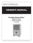
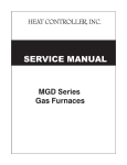
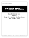
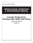
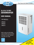
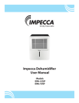
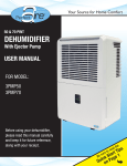
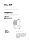
SERVICE MANUAL
Portable Dehumidifer Series
with R-410A:
BHD-301-G
BHD-501-G
BHD-651-G
Heat Controller, Inc. • 1900 Wellworth Ave. • Jackson, MI 49203 • (517)787-2100 • www.heatcontroller.com
BHD-G Service Manual
Portable Dehumidifier with R-410A
Heat Controller, Inc.
TABLE OF CONTENTS
1. PREFACE............................................................................................. 2
1.1 SAFETY PRECAUTIONS....................................................... 2
1.2 INSULATION RESISTANCE TEST......................................... 2
1.3 UNIT FEATURES.................................................................... 2
1.4 CONTROL LOCATIONS......................................................... 2
1.5 OUTSIDE DIMENSIONS........................................................ 3
2. Product Installation Instructions ..................................................... 4
3. Product Operation.............................................................................. 4
3.1 Operating Conditions:............................................................. 4
3.2 Turning the unit “ON” or “OFF”............................................... 4
3.3 Operation with Water Tank..................................................... 4
3.4 Operation with Continuous drainage...................................... 5
3.5 MAINTENANCE..................................................................... 5
4. Electronic function............................................................................. 6
4.1 Powering on the unit............................................................... 6
4.2 Setting the relative humidity................................................... 6
4.3 Continuous Dehumidification mode........................................ 6
4.4 Powering off the unit............................................................... 6
4.5 Compressor protection........................................................... 6
4.6 Protection and failure mode................................................... 6
5. Basic Test Procedures....................................................................... 7
5.1 Defective Compressor............................................................ 7
5.2 SEALED REFRIGERATION SYSTEM REPAIRS.................. 8
5.3 FAN MOTOR.......................................................................... 9
5.4 CAPACITOR........................................................................... 9
6. TROUBLESHOOTING GUIDE............................................................11
6.1 TROUBLESHOOTING GUIDE.............................................11
6.2 Fault Codes..........................................................................11
6.3 TROUBLE SHOOTING.........................................................11
7. WIRING DIAGRAM............................................................................ 15
1
Heat Controller, Inc.
Portable Dehumidifier with R-410A
BHD-G Service Manual
1. PREFACE
This SERVICE MANUAL provides various servicing information for the unit, including the mechanical and electrical
parts, etc. This dehumidifier was manufactured and assembled under a strict quality control system.
The refrigerant is charged at the factory. Be sure to read the safety precautions prior to servicing the unit.
1.1 SAFETY PRECAUTIONS
1. When servicing the unit, set the POWER SWITCH to OFF and unplug the power cord.
2. Inspect the service cord for damage or wear.
If a short circuit is found, replace all parts which have been overheated or damaged by the short circuit.
3. After servicing the unit, conduct an insulation resistance test to protect the user from being exposed to
electrical shock hazards.
1.2 INSULATION RESISTANCE TEST
1. Unplug the power cord and connect a jumper lead between the two (2) live test pins.
2. The grounding conductor (yellow/green) should be open.
3. Measure the resistance value with an ohm meter between the jumped lead and each exposed metallic part
on the unit at all the positions (except OFF) on the ROTARY SWITCH or POWER SWITCH.
4. The value should be over 1MΩ.
1.3 UNIT FEATURES
•
•
•
•
•
•
•
Auto-defrosting.
Suitable for low-temperature and high-humidity weather.
Water-full alarm and auto shutdown functions.
Powerful dehumidification in wide temperature range between 41°F-90°F (5°C~32°C)
LED display.
Humidity display and setting.
Self diagnose and defect display
1.4 CONTROL LOCATIONS
Control pads:
When you push the button to change operation modes, the unit will make a beep sound to indicate that it is changing modes.
1. POWER
Press to turn the dehumidifier on and off.
2. CHECK FILTER
The check filter feature is a reminder to clean the Air Filter for more efficient operation. The LED light will
illuminate after 250 hours of operation. To reset after cleaning the filter, press CHECK FILTER and the light
will go off.
2
BHD-G Service Manual
Portable Dehumidifier with R-410A
Heat Controller, Inc.
3. Humidity Set Control
The humidity level can be set within a range of 35%RH (Relative Humidity) to 85%RH (Relative Humidity) in 5%
increments.
For drier air, press the button and set to a lower percent value(%). When the value displays 35%,press
the
button again will activate the continuous dehumidifying operation. For damper air, press the button
and set a higher percent value(%).
TIMER Set Control
Use the (+) or (-) buttons to set the Auto start and Auto stop time from 0.0 to 24 hours.
4. Fan speed
Control the fan speed. By pressing either High or Normal fan speed. Set the fan control to High for maximum moisture removal. When the humidity has been reduced and quieter operation is preferred, set the fan control to Normal.
5. TIMER
Press to initiate the Auto start and Auto stop feature, in conjuction with the
6. Display
and
keys.
Shows the set % humidity level from 35% to 85% or auto start/stop time (0~24 hours) while setting, then shows
the actual (+5% accuracy) room % humidity level in a range of 30%RH (Relative Humidity) to 90%RH(Relative
humidity).
Error Codes:
AS- Humidity sensor error--Unplug the unit and plug it back in. If error repeats, call for service.
ES- Temperature sensor error-- Unplug the unit and plug it back in. If error repeats, call for service.
P1- Unit is defrosting-- Allow the unit time to automatically defrost. The error will clear after the unit self defrosts.
P2- Bucket is full-- Empty the bucket and replace in the right position.
CO- Continuous dehumidifying mode is selected.
1.5 OUTSIDE DIMENSIONS
Width
in. (mm)
Height
in. (mm)
Depth
in. (mm)
BHD-301-G
13.28” (340)
19.88” (505)
9.96” (253)
BHD-501-G
BHD-651-G
15.47” (393)
24.49” (622)
12.64” (321)
Model
3
Heat Controller, Inc.
Portable Dehumidifier with R-410A
BHD-G Service Manual
2. Product Installation Instructions
Install the portable dehumidifier in a flat and spacious location where the air outlets will not be obstructed. Do not
install underneath desks or inside cupboards as this will restrict the air flow.
Maintain a clearance of at least 8 inches (20cm) in the front and rear of the unit to
maintain correct air-flow.
3. Product Operation
16in (40cm)
or more
8in (20cm) or more
8in (20cm) or
more
3.1 OPERATING CONDITIONS:
This unit is designed to operate in an environment between 41°F-90°F (5°C and
8in (20cm) or more
8in (20cm) or more
35°C).
If the unit has been switched off and needs to be switched on again quickly, allow approximately three minutes for
the compressor to start up and for dehumidifaction to resume.
Do not connect the dehumidifier to a multiple socket outlet, which is also being used for other electrical appliances.
Select a suitable location, making sure you have easy access to an electrical outlet.
Plug the unit into a 115V~60Hz electrical socket-outlet with a ground connection.
Make sure the Water Tank is correctly inserted otherwise the unit will not operate properly.
3.2 TURNING THE UNIT “ON” OR “OFF”
3.2.1 Plug the cord to the proper power recepticable. The unit’s program will run a self-check, if it is normal, the
power indicator flashes (at 0.5Hz). Press Power button now, the unit will start operating under DEHUMIDIFYING
mode with 60% setting humidity. Press the Humidity (+) or (-) button will change humidity setting.
3.2.2 Press Continuous button to start the continous dehumidification mode. During this mode, the Humidity (+) or
(-) button are disabled.
3.2.3 Press the Power button to turn off the unit.(You do not need to unplug the power cord except when the unit will
not be in use for a long period of time.)
3.3 OPERATION WITH WATER TANK
Water will drain into the tank. When the tank is full, the unit stops operating, the water Full indicator light will flash.
Do not remove the water tank while the machine is still working wait for the unit to completely stop to remove the
bucket.
If not, some water may drip.
To empty the water tank, remove the tank as shown, empty the water and replace the tank back in the unit. Ensure
components of water tank are correctly positioned.
The unit will re-start when the water tank is restored to its correct position.
1. Pull out the bucket a
little.
2. Hold both sides of the
bucket with even strength,
and pull it all the way out
from the unit.
4
3. Pour the water out
BHD-G Service Manual
Portable Dehumidifier with R-410A
Heat Controller, Inc.
3.4 OPERATION WITH CONTINUOUS DRAINAGE
On the rear of the unit, remove the rubber plug carefully.
Remove the water tank first, then push the hose onto the connector located inside of the hole.
The hose should go down smoothly without bends or kinks.
Place the end of the hose into a suitable drainage location for condensate removal.
3.5 MAINTENANCE
3.5.1 Precaution
Be sure to unplug the unit before cleaning.
Do not use harsh detergents, thinners or other chemical agents to clean the unit as this may damage the unit.
Do not wash the unit directly under a tap or hose. The electrical components inside may be damaged and the unit
become unsafe as a result.
3.5.2 Air filter
Clean the air filter at least once every two weeks to prevent impaired performance of the unit.
Pull the air filter out and Wash the air filter with clean water, and then carefully dry (see figure below).
3.5.3 Unit enclosure
Use a soft, clean cloth to wipe the surface. Do not use water as this may cause an electrical fault or shock hazard.
3.5.4 Water tank
Wash the tank using warm water 104°F (about 40°C) with neutral detergent. Rinse and allow
to air dry. Replace tank when dry.
5
Heat Controller, Inc.
Portable Dehumidifier with R-410A
BHD-G Service Manual
4.Electronic function
4.1 POWERING ON THE UNIT
When the unit is just powered on or the dropped power is just restored, the unit will immediately perform the selfdiagnosis. The check items include the water-full, temperature sensor and humidity sensor. If there is no defect, the
power LED will flash at 0.5Hz while all other LEDs are off. All buttons are invalid except the ON/OFF button.
4.2 SETTING THE RELATIVE HUMIDITY
When the ON/OFF button is pressed for the first time, after the unit has been off or has experienced a power failure, the unit will operate according to the original factory setting humidity of 60% RH. The humidity setting can be
changed by pressing the (+) or (-) buttons. Under normal operation, when the indoor humidity is 5% higher than the
set humidity, the compressor will turn on, the fan speed with be low with the NORMAL light on. When the indoor
humidity becomes lower than the set humidity, the compressor will turn off, but the fan will remain on in order to
continuously sample the air’s humidity, remove air debris/pollutants through the air filter, and to provide better air
circulation. When the humidistat senses that the room’s actual humidity is 5% higher that the set humidity, the compressor will restart and begin to dehumidify the air, until the set humidity level is achieved. This cycle will continue in
order to maintain the humidity level of the air as desired by the set humidity level. The only exception to this operation cycle is outlined below when the unit is placed into continuous mode by the user.
4.3 CONTINUOUS DEHUMIDIFICATION MODE
When the set humidity level is at 35% and the (-) button is pressed again, the unit will go into CONTINUOUS
DEHUMIDIFICATION MODE. The display on the unit will show ‘CO’. In this mode, the unit will maintain the room’s
humidity level at 35% as the standard setting. The set humidity level can not be adjusted, unless the (+) button is pressed
twice and ‘CO’ is no longer displayed. Within the continuous mode, the compressor will cycle on and off as necessary,
automatically to maintain the 35% humidity level. The fan will remain on with in NORMAL or TURBO mode, as selected
by the user or indicated by the light on the display. The fan speed can be changed by the user to be in either TURBO or
NORMAL modes, however it never cycles off. The fan will remain on in order to continuously sample the air’s humidity,
remove air debris/pollutants through the air filter, and to provide better air circulation. When the humidistat senses that
the room’s actual humidity is 5% higher than the set humidity of 35% in continuous mode, the compressor will restart and
begin to dehumidify the air, until the set humidity level is achieved again. This cycle will continue in order to maintain the
humidity level of the air as desired by the set humidity level at 35% within the continuous mode.
4.4 POWERING OFF THE UNIT
The unit is stopped by pressing the ON/OFF button, the compressor and the fan will shut down and all indicator
lights will turn off. The time for defrost will be allotted. When the unit is restarted by pressing the ON/OFF button,
the unit will start with previous set mode and fan speed. The defrost function begin. The self-diagnosis function will
check if the water bucket is full. The fan motor will turn on with the compressor.
4.5 COMPRESSOR PROTECTION
The compressor has a 3 minute time delay before it will restart if the unit was turned off.
4.6 PROTECTION AND FAILURE MODE
4.6.1 Water full protection. When the water tank is full , the compressor and fan motor will shut down and the water
full indicator will flash with LED displaying P2. Under this situation, all button will not operate. After the water is
removed from the bucket, the unit will restore operating at the previous setting.
4.6.2 Anti icing protection.
4.6.2.1 If after 15 minutes the compressor is operating and the temperature of the evaporator is lower than
30°F (-1°C), the Anti-icing protection function will be activated.
4.6.2.2 When the protection is activated, the compressor will turn off while the fan motor turns on at high fan
speed, and the Turbo indicator will be on with the LED displaying P1. The time will also be cleared.
4.6.2.3 After the compressor has remained off and the fan has stayed on high fan speed for 6 minutes, then
the unit will stop anti-icing protection function.
4.6.2.4 If the temperature sensor has failed, the time will be cleared from the display. If the water full error has
occurred, the time will just stop, but not be cleared from the display.
4.6.2.5 After the Anti-icing function is complete, the unit will restore operation from the previous mode.
4.6.3 Sensor failure check. When the output voltage of sensor is lower than 0.5V or higher than 4.95V, the unit will
alarm and the LED displays E1 for humidity sensor failure and E2 for temperature sensor failure. Under this situation,
the compressor and the fan motor will shut down and the Power indicator will flash at 5Hz. After the defect is cleared,
the unit will not work until the power to the unit is re-stored.
4.6.4 When the water full and sensor failure occur together, the water full alarm has the priority on display.
6
BHD-G Service Manual
Portable Dehumidifier with R-410A
Heat Controller, Inc.
5.Basic Test Procedures
5.1 DEFECTIVE COMPRESSOR
Compressors are single phase, 115 volt. All compressor motors are permanent split capacitor type using only a
running capacitor across the start and run terminal.
All compressors are internally spring mounted and externally mounted on rubber isolators.
COMPRESSOR WINDING TEST
Remove compressor terminal box cover and disconnect wires from terminals.
Using an ohmmeter, check continuity across the following:
1. Terminal “C” and “S” - no continuity
- open winding - replace compressor.
2. Terminal “C” and “R” - no continuity
- open winding - replace compressor.
3. Terminal “R” and “S” - no continuity
- open winding - replace compressor.
Figure 1: Compressor winding test
GROUND TEST
Use an ohmmeter set on its highest scale. Touch one lead to the compressor body (clean point of contact as a
good connection is a must) and the other probe in turn to each compressor terminal (see Figure 2.) If a reading is
obtained, the compressor is grounded and must be replaced.
CHECKING COMPRESSOR EFFICIENCY
The reason for compressor inefficiency is normally due to broken or
damaged suction and/or discharge valves, reducing the ability of the
compressor to pump refrigerant gas.
This condition can be checked as follows:
1. Install a piercing valve on the suction and discharge or liquid line.
2. Attach gauges to the high and low sides of the system.
3. Start the system and run a “cooling or heating performance test.”
If test shows:
A. Below normal high side pressure.
B. Above normal low side pressure.
C. Low temperature difference across coil.
The compressor valves are faulty - replace the compressor.
Figure 2: Typical ground test
THERMAL OVERLOAD (External)
Some compressors are equipped with an external overload which is located in the compressor terminal box
adjacent to the compressor body. The overload is wired in series with the common motor terminal. The overload
senses both amperage and compressor temperature. High motor temperature or amperage heats the disc causing it
to open and break the circuit to the common motor terminal.
Heat generated within the compressor shell is usually due to:
1. High amperage.
2. Low refrigerant charge.
3. Frequent cycling.
4. Dirty condenser.
TERMINAL OVERLOAD – TEST (Compressor - External Type)
1. Remove overload.
2. Allow time for overload to reset before attempting to test.
3. Apply ohmmeter probes to terminals on overload wires. There
should be continuity through the overload.
7
Heat Controller, Inc.
Portable Dehumidifier with R-410A
BHD-G Service Manual
TERMINAL OVERLOAD (Internal)
Some model compressors are equipped with an internal overload. The overload is embedded in the motor windings
to sense the winding temperature and/or current draw. The overload is connected in series with the common motor
terminal.
Should the internal temperature and/or current draw become excessive, the contacts in
the overload will open, turning off the compressor. The overload will automatically reset,
but may require several hours before the heat is dissipated.
CHECKING THE INTERNAL OVERLOAD
1. With no power to unit, remove the leads from the compressor terminals.
2. Using an ohmmeter, test continuity between terminals C-S and C-R. If not continuous,
the compressor overload is open and the compressor must be replaced.
5.2 SEALED REFRIGERATION SYSTEM REPAIRS
EQUIPMENT REQUIRED
1. Voltmeter
2. Ammeter
3. Ohmmeter
4. E.P.A. Approved Refrigerant Recovery System.
5. Vacuum Pump (capable of 200 microns or less vacuum.)
6. Acetylene Welder
7. Electronic Halogen Leak Detector (G.E. Type H-6 or equivalent.)
8. Accurate refrigerant charge measuring device such as:
a. Balance Scales - 1/2 oz. accuracy
b. Charging Board - 1/2 oz. accuracy
9. High Pressure Gauge - (0 - 400 lbs.)
10. Low Pressure Gauge - (30 - 150 lbs.)
11. Vacuum Gauge - (0 - 1000 microns)
EQUIPMENT MUST BE CAPABLE OF:
1. Recovery CFC’s as low as 5%.
2. Evacuation from both the high side and low side of the system simultaneously.
3. Introducing refrigerant charge into high side of the system.
4. Accurately weighing the refrigerant charge actually introduced into the system.
5. Facilities for flowing nitrogen through refrigeration tubing during all brazing processes.
HERMETIC COMPONENT REPLACEMENT
The following procedure applies when replacing components in the sealed refrigeration circuit or repairing
refrigerant leaks. (Compressor, condenser, evaporator, capillary tube, refrigerant leaks, etc.)
1. Recover the refrigerant from the system on the high side of the system by installing a line tap on the line.
Apply gauge from line to EPA approved gauges from line to EPA approved recovery system. Recover CFCs
in system to at least 5%.
2. Cut the line below, pinch off the suction side of the compressor.
3. Connect the line from the nitrogen tank to the suction line.
4. Add dry nitrogen through the system and unsolder the more distant connection first. (Filter drier, high side
process tube, etc.)
5. Replace inoperative component, and always install a new filter drier. Add dry nitrogen through the system
when making these connections.
6. Pressurize system to 30 PSIG with proper refrigerant and boost refrigerant pressure to 150 PSIG with dry
nitrogen.
7. Leak test complete system with electric halogen leak detector, correcting any leaks found.
8. Reduce the system to zero gauge pressure.
9. Connect vacuum pump to high side and low side of system with deep vacuum hoses, or copper tubing. (Do
not use regular hoses.)
10. Evacuate system to maximum absolute holding pressure of 200 microns or less. NOTE: This process
can be sped up by use of heat lamps, or by breaking the vacuum with refrigerant or dry nitrogen at 5,000
microns. Pressure system to 5 PSIG and leave in system a minimum of 10 minutes. Recover refrigerant,
and proceed with evacuation of a pressure of 200 microns or a minimum of 10%.
8
BHD-G Service Manual
Portable Dehumidifier with R-410A
Heat Controller, Inc.
11. Break vacuum by charging system from the high side with the correct amount of refrigerant specified. This
will prevent boiling the oil out of the crankcase.
NOTE: If the entire charge will not enter the high side, allow the remainder to enter the low side in small
increments while operating the unit.
12. Restart unit several times after allowing pressures to stabilize. Pinch off lines, cut and solder the ends.
Remove pinch off tool, and leak check the line ends.
COMPRESSOR MOTOR BURNOUT
1. Recover all refrigerant and oil from the system.
2. Remove compressor, capillary tube and filter drier from the system.
3. Flush evaporator condenser and all connecting tubing with dry nitrogen or equivalent, to remove all
contamination from system. Inspect suction and discharge line for carbon deposits. Remove and clean if
necessary.
4. Reassemble the system, including new drier, strainer and capillary tube.
5. Proceed with processing as outlined under hermetic component replacement.
ROTARY COMPRESSOR TROUBLESHOOTING AND SERVICE
Basically, troubleshooting and servicing rotary compressors is the same as a reciprocating compressor with a few
exceptions.
1. Because of the spinning motion of the rotary compressor, the mounts are critical. If vibration is present,
check the mounts carefully.
2. The electrical terminals on the rotary compressor are in a different order than the reciprocating compressors.
The terminal markings are on the cover gasket. Use the wiring diagram to insure correct connections.
REFRIGERANT CHARGE
1. The refrigerant charge is extremely critical. Measure charge carefully - as exact as possible to the nameplate
charge.
2. The correct method for charging the rotary compressor is to introduce liquid refrigerant into the high side of the
system with the unit off. Then start compressor and add the balance of the charge, gas only, into the low side.
The introduction of liquid into the low side, without the use of a capillary tube, will cause damage to the
discharge valve of the rotary compressor.
5.3 FAN MOTOR
A single phase permanent split capacitor motor is used to drive the evaporator blower and condenser fan. A selfresetting overload is located inside the motor to protect against high temperature and high amperage conditions.
FAN MOTOR - TEST
1. Determine that capacitor is serviceable.
2. Disconnect fan motor wires from fan speed switch or system switch.
3. Apply “live” test cord probes on black wire and common terminal of capacitor. Motor should run at high
speed.
4. Apply “live” test cord probes on red wire and common terminal of capacitor. Motor should run at low speed.
5. Apply “live” test cord probes on each of the remaining wires from the speed switch or system switch to test
intermediate speeds.
5.4 CAPACITOR
A run capacitor is wired across the auxiliary and main winding of a
single phase permanent split capacitor motor such as the compressor
and fan motor. A single capacitor can be used for each motor or a dual
rated capacitor can be used for both.
The capacitor’s primary function is to reduce the line current while
greatly improving the torque characteristics of a motor. The capacitor
also reduces the line current to the motor by improving the power factor
of the load. Run capacitor hook-up line side of the capacitor is marked
with a red dot and is wired to the line side of the circuit
9
Heat Controller, Inc.
Portable Dehumidifier with R-410A
BHD-G Service Manual
CAPACITOR - TEST
1. Remove capacitor from unit.
2. Check for visual damage such as bulges, cracks, or leaks.
3. For dual rated, apply an ohmmeter lead to common (C) terminal and the other probe to the compressor
(HERM) terminal. A satisfactory capacitor will cause a deflection on the pointer, then gradually move back to
infinity.
4. Reverse the leads of the probe and momentarily touch the capacitor terminals. The deflection of the pointer
should be two times that of the first check if the capacitor is good.
5. Repeat steps 3 and 4 to check fan motor capacitor.
NOTE: A shorted capacitor will indicate a low resistance and the pointer will move to the “0” end of the scale and
remain there as long as the probes are connected.
An open capacitor will show no movement of the pointer when placed across the terminals of the capacitor.
10
Portable Dehumidifier with R-410A
BHD-G Service Manual
Heat Controller, Inc.
6. TROUBLESHOOTING GUIDE
6.1 TROUBLESHOOTING GUIDE
In general, possible trouble is classified in three kinds. One is called Starting Failure which is caused from an electrical defect, another is ineffective Air Conditioning caused by a defect in the refrigeration circuit and improper application, and the other is called the Structure Damage.
ROOM AIRCONDITIONER VOLTAGE LIMITS:
NAMEPLATE RATING
MINIMUM
MAXIMUM
115V
103V
127V
6.2 IDENTIFY ALL POSSIBLE PCB FAULT CODES
P1: Anti icing protection. When the protection is activated, the compressor will be off while the fan motor is on with high
speed, and the Turbo indicator will be on with the LED displaying P1. After the Anti-icing function is completed, the unit
will restore operation in the previous mode.
P2: Water full protection. When the water tank is full , the compressor and fan motor will shut down and the water full
indicator will flash with LED displaying P2. Under this situation, all buttons are deactivated. After the water is removed,
the unit will restore operating at the previous setting.
E1: Humidity sensor failure. When the output voltage of sensor is lower than 0.5V or higher than 4.95V, the unit will
alarm and the LED displays E1. After the defect is cleared, the unit will not work until the power to the unit is re-stored.
E2: Temperature sensor failure. When the output voltage of sensor is lower than 0.5V or higher than 4.95V, the unit will
alarm and the LED displays E2. After the defect is cleared, the unit will not work until the power to the unit is re-stored.
6.3 TROUBLE SHOOTING
6.3.1 Water level protection function abnormal
Abnormal water level protection function includes the following: (1) There is an alarm when the water level is normal
and (2) There is no alarm for full water.
6.3.2 Automatic trouble alarm
When the line temperature sensor is defective, the motors of the compressor and the fan will shut down, and the
power indicator will flash at 5 Hz.
11
Heat Controller, Inc.
Portable Dehumidifier with R-410A
6.3.3 Humidity sensor check
6.3.4 Fail to start or fail to start motor
12
BHD-G Service Manual
Portable Dehumidifier with R-410A
BHD-G Service Manual
Heat Controller, Inc.
6.3.5 Abnormal noise
Check whether the lines
are vibrating or coming
into contact with other
lines or compressor
Check whether the noise
is from inside the line.
6.3.6 Complaint and remedy
Complaint
No display or any button
failure.
Fan motor will not run.
Cause
Remedy
Transformer (Discharge
transformer before
testing)
Check resistance between the two input/output lines on
transformer. Replace the transformer if either of the input/
output is open or the transformer is damaged.
Display board or main
PCB failure.
Replace the display board if it is +5V or else replace the
main PCB.
No power
Check voltage at electrical outlet. Correct if none.
Power supply cord
Check voltage at the power cord terminal on Main PCB.
Replace the power cord if no voltage.
Transformer (Discharge
transformer before
testing)
Check resistance between the two input/output lines on
transformer. Replace the transformer if either of the input/
output is open or the transformer is damaged.
Wire disconnected or
connection loose
Reconnect wire. Refer to wiring diagram for terminal
identification. Repair or replace loose terminal.
Main PCB failure
Select fan speed and check the voltage of P1, P2 on main
PCB. Replace the main PCB if no voltage.
Capacitor (Discharge
capacitor before testing)
Test capacitor. Replace if not within 10% of manufacturer’s
rating. Replace if shorted, open or damaged.
Will not rotate
Fan blade hitting shroud or blower hitting scroll. Realign
assembly. Check fan motor bearings. Replace the motor if
motor shaft does not rotate.
Check voltage. Call an electrician if not with in limits.
Fan motor runs intermittently
Revolves on over load.
Test capacitor. Replace if not within 10% of manufacturer’s
rating. Replace if shorted, open or damaged.
Check bearings. Replace the motor if the fan blade can’t
rotate freely.
Pay attention to any change from high speed to low speed.
Replace the motor if the speed does not change.
Excessive noise
Stops instantly after startup.
Copper tubing
Remove the cabinet and carefully rearrange tubing not to
contact cabinet, compressor, shroud and/or barrier.
Refrigerant
The amount of the refrigerant is too much, making the
compressor load too big. Recycle and recharge the
refrigerant after checking the charge amount.
Compressor
The compressor overheated. Replace.
13
Portable Dehumidifier with R-410A
Heat Controller, Inc.
Complaint
Fan motor noise
Compressor fan motor runs
only
Insufficient capacity
Cause
Remedy
Fan
Replace the fan if cracked, out of balance, or partially
missing.
Blower
Replace the blower if cracked, out of balance, or partially
missing.
Loose screws
Tighten them.
Worn bearings
Replace the motor if knocking sounds continues when
running, or if the motor hums or noise appears to be internal
while running.
Voltage
Check voltage. Call an electrician if not within limits.
Wiring
Check the wire connections, if loose, repair or replace
the terminal. If wires are off, refer to wiring diagram for
identification, and replace. Check wire locations. If not per
wiring diagram, correct.
Main PCB failure
Replace the main PCB.
Capacitor (Discharge
capacitor before testing)
Check the capacitor. Replace if not within 10% of
manufacturer’s rating. Replace if shorted, open, or damaged.
Humidity sensor
Replace if shorted, open, or damaged.
Compressor
Check the compressor for open circuit or ground. If open or
grounded, replace the compressor.
Air filter
Clean if restricted.
Condenser and
Evaporator
Clean if restricted.
Fan motor
Check the fan capacitor and replace if not within 10% of
manufacturer’s rating.
Room structure
Ensure that the room the unit is operating in is sealed well.
Close any open doors or windows.
Air flow
Clean or remove any barrier that blocks the inlet/outlet air
flow of the unit.
Less refrigerant
Check the lines for leakage. Recycle the refrigerant, correct
the leakage points and recharge.
Capillary tube
Regulate the flow of capillary tube and make the evaporating
temperature appropriate if the evaporator is frosted.
Compressor
The inlet and outlet valve of the compressor is damaged,
making the low pressure connected with the high pressure.
The refrigerating system is difficult to produce high pressure
and low pressure. Replace the compressor after checking
for the failure.
The compressor does not stop
Humidity sensor
even if the room humidity has
reached the set RH%.
Main PCB
The unit starts and stops
frequently.
BHD-G Service Manual
Check and replace if the Humidity sensor, if open or
damaged.
Check and replace the main PCB
Power supply
The input power supply voltage is too low. Call an electrician
if not within limits.
Humidity sensor
Check and replace if the Humidity sensor, if open or
damaged.
Main PCB
Check and replace the main PCB.
14
BHD-G Service Manual
Portable Dehumidifier with R-410A
7. Wiring Diagram
15
Heat Controller, Inc.
04/2009
05/2010