1
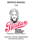
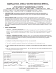
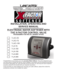
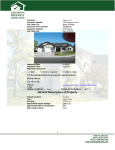
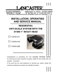
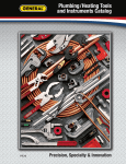
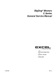
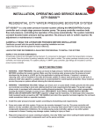
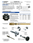
INSTALLATION, OPERATING
AND SERVICE MANUAL
ECONO-mist WATER SOFTENER
Demand Regeneration
7-LMC56-75
7-LM56-75
7-LM56-100
7-LM56-150
7-LM56-200
Congratulations on purchasing your new Lancaster Water Softener. This unit is
designed to give you many years of trouble free service. When installed in
accordance with the following instructions and if given reasonable care, clear-soft
water will be the result. For servicing and future inspection purposes, please file
this booklet with your important documents.
INSTALLATION
Place softener in desired location close to water supply inlet, after pressure tank, and near a source for waste water, (utility sink,
floor drain or sewer line). Keep far enough away from walls and other obstructions to allow enough room for servicing the unit.
All sillcocks and similar fixtures that will use untreated water must have their pipes connected to the hard water side of the
softener. A bypass valve (optional accessory) should be installed so that water will be available if it should be necessary to shut
off the pressure in order to service the softener.
The cabinet tank or mineral tank must be reasonably level and solidly in place. Prior to beginning work to the system, make sure
that water pressure is shut off at the incoming water supply and that several water spigots are open to prove sufficient venting
for drainage of that system.
Arrows are molded into the control valve to show the direction of the flow.
OPTIONAL BYPASS VALVE: The bypass valve easily connects to the control valve body using screws and adapter clips.
Install with red handle in the upward position. Press slip end of bypass valve onto in/out connections of valve. Take care not to
crimp o-rings. Place into BYPASS POSITION. Do not use Vaseline or other unacceptable lubricants on o-rings. A silicone
lubricant may be used on black o-rings.
DRAIN LINE: Drain line fitting accommodates 1/2” I.D. flexible poly tube.
It is simplest to run the drain line into a sump pump pit or washing machine drain if possible. If this is not practical, a fitting with a
trap must be installed in a sewer line. Place the trap as close to the vent as possible to prevent siphoning of the trap when large
amounts of waste water go through the sewer line. DO NOT pipe the drain line solidly into the waste line, as this is
prohibited by most plumbing codes. The drain line should enter the trap from above so the water will not back up in the drain line
if sewer should become plugged up and the trap overflow. The trap should have a short pipe extending from it to prevent
splashing when water runs into the trap from drain line.
BRINE LINE CONNECTIONS: 3/8” poly tube is
shipped inside of the brine tank along with a fittings
package.
MAKE CONNECTION TO BRINE TANK: Loosen nut
on brine tank connection. Push the tube insert into
the provided 3/8” poly tube. Push the poly tube and
insert into the nut until it is fully seated into the
fitting. Do not use pipe dope or any other sealant on
threads. Teflon tape is not needed on the threads.
Tighten nut securely to create a pressure tight
connection. Pliers or crescent wrench may be used.
The nut, gripper and retainer sleeve is a three piece
assembly that can come apart if removed from the
elbow body. Parts must be reassembled exactly as
shown to function properly. If the nut is completely
removed from the body, slip the nut, plastic gripper
and retainer sleeve on to the tube then tighten on to
the fitting.
MAKE CONNECTION TO CONTROL VALVE: Slide
brass nut onto 3/8” poly tube. Slide ferrule onto poly
tube as shown in diagram. Install tube insert. Press
fully into brine valve fitting. Tighten brass nut.
BRINE TANK OVERFLOW PRECAUTION:
Attach a 1/2” poly tube (not provided) to the barbed
fitting on the outside of the tank. This poly tube
should be piped to drain to allow brine to discharge
to drain in the event of an overflow condition.
SANITIZING: Use 2 oz. of 5¼% household
chlorine bleach for each cubic foot of resin. Pour
bleach directly into the brine well of the softener.
Manually index the softener to the REGEN position.
Allow system to complete the regeneration
automatically. Check for other local and state codes
which may also specify sanitation methods. This is
to be done after placing unit into service. (see next
page.)
Page 2
PLACING UNIT INTO SERVICE:
1.
Manually index the softener control into the backwash position. Slowly open bypass valve and allow water to flow into the
resin tank. When the water flows steadily to drain without the presence of air, index control to service position.
NOTE: the various regeneration positions may be dialed manually by turning the knob on the front of the control clockwise
until the indicator shows that the softener is in the desired position. VARIOUS REGENERATION POSITIONS ARE:
1. IN SERV.
3. RINSE
5. BRINE + RINSE
7. SETTLE RINSE
2. REGEN.
4. BACK WASH
6. RAPID RINSE
8. BRINE REFILL
2.
Set water usage program wheel using the following procedure:
Typical Residential Application: To program the unit, set the correct time of day, set the hardness of your water and
softener will automatically monitor your usage, regenerating only when necessary. To set time of day press red time set
button and turn 24 hour gear until present time of day is opposite “time of day.” Set program wheel by lifting the
“people” dial
and rotating it so that the number of people in the household is aligned with the “grains per gallon” water
the
3.
4.
5.
Rotate the program wheel
counter clockwise until it
stops at regeneration position.
Add 1-1/2 gallons of water
to the brine tank.
Plug in the electrical cord and
look in the sight hole in the
back of the motor to see that it
is running.
6.
Manually advance the
control to the beginning of the
brine
refill position and allow the
control to return to the
service position automatically.
7.
Fill the brine tank with salt. Maintain salt level above water level. We recommend Solar Salt.
8.
Make sure bypass valve(s) is in the service position.
Page 3
Item No.
Qty.
Part No.
Description
Item No.
1
1
15494
Drive Panel
22
Qty. Part No.
1
19205
Description
24 Hour Gear Assy.
2
1
14333
Front Label
24
1
14176
Valve Position Dial
3
1
13018
Idler Pinion
25
1
14177
Knob
4
1
13312
Idler Spring
26
1
15151
Screw - Knob
5
1
13017
Idler Gear
27
1
14207
Knob Label
6
1
13164
Drive Gear
28
1
60405-15
Program Wheel Assy.
7
1
13299
Curved Washer
29
1
13806
Program Wheel Retainer
8
1
13175
Motor Mounting Plate
30
1
13748
Screw - Program Wheel
9
1
18743
Motor - 110 V. 1/30 RPM
31
1
13953
Cover Label - Program Wheel
10
3
11384
Screw
32
1
13830
Drive Pinion - Program Wheel
11
3
13296
Screw
33
1
13831
Clutch - Drive Pinion
12
2
14457
Spring
34
1
14276
Spring
13
2
13300
Ball
35
1
14253
Spring Retainer
14
1
13170
Main Gear & Shaft
36
1
14043
Flexible Cable Assy.
15
1
60514
Brine Cam Assy. LMC56-75, LM56-75, LM56-100
37
1
13547
Strain Relief
1
60514-01 Brine Cam Assy. LM56-150, LM56-200
38
1
11842
Electrical Cord
20
1
12037
Washer
39
2
12473
Screw-Drive Mounting
21
1
13802
Cycle Actuator Arm
40
1
60226
Black Cover
Page 4
Item No. Qty.
Part No.
Description
Item No. Qty. Part No. Description
1
4
13255
Adapter Clips
22
1
13163
Injector Body
2
5
13424
Seals
23
1
10913
Injector Nozzle
3
1
61400-12
Valve Body Assy . - 1”
24
1
10914
Injector Throat
4
1
13304
O-Ring
25
1
10227
5
1
12281
O-Ring
26
1
6
4
12473
Screw
27
7
4
14241
Spacer
8
1
13247
Piston
9
1
10696
10
1
11
Item No. Qty.
1
12086
1.5 GPM Button
1
12089
2.4 GPM Button
43
1
13173
Retainer
Injector Screen
44
1
12767
Screen
13166
Injector Cover
45
1
13821
Meter Body
1
13172
Brine Valve Stem
46
1
13497
Air Disperser
28
1
12626
Brine Valve Seat
47
1
13546
End Plug Retainer
29
1
13165
Brine Valve Cap
48
3
12112
Screws
Piston Pin
30
1
13167
Brine Valve Spacer
49
1
13363
Washer
13001
Piston Rod Assy.
31
1
12550
Quad Ring
50
1
13296
Screw
1
12953
Piston Retainer
32
1
11973
Spring
51
1
13398
Yoke, Stainless Steel
12
1
13446
End Plug Assy.
33
1
16098
Washer
52
1
13308
Drain Line Fitting
13
1
13847
O-Ring
34
1
11981
Retaining Ring
53
1
14038
Meter Cover Assy.
14
2
13315
Screw
35
1
10329
Fitting Nut
1
15150
Meter Cover - Extended
15
1
14613
Flow Straightener
36
1
10330
Ferrule
54
1
13509
Impeller
16
4
13305
O-Ring
37
1
10332
Tube Insert
55
1
15348
O-Ring
17
4
13314
Screw
38
1
12094
Button - .25 GPM
60032
Brine Valve Assy.
18
1
12638
O-Ring
1
12095
Button - .50 GPM
60084
Injector/Drain Assy.
19
2
13301
O-Ring
39
1
12977
O-Ring
60102-
Piston Assy.
20
2
13302
O-Ring
40
1
13245
Retainer
60125
Seal Kit
21
1
13303
O-Ring
41
1
13244
B.L.F.C. Fitting
Page 5
42
Part No. Description
4740 Brine Valve Assembly
Item No. Quantity
Part No.
Description
1
1
H4600
3/8” Safety Brine Valve
2
1
10151
Pin
3
1
H4640-32
Float Assembly
4
1
H4500-30.50 Air Check Assembly
Page 6
SERVICE INSTRUCTIONS
TO REPLACE BRINE VALVE, INJECTORS, AND SCREEN: Unplug electrical cord from outlet. Turn off water supply to
softener. Relieve water pressure in the softener by putting the control in the backwash position momentarily. Return the control
to the service position. Disconnect brine tube and drain line connections at the injector body. Remove the two injector body
mounting screws. The injector and brine module can now be removed from the control valve. Remove and discard valve body
O-Rings.
TO REPLACE BRINE VALVE: Pull brine valve from injector body, also remove & discard O-Ring at bottom of brine valve hole.
Apply silicone lubricant to new O-Ring and reinstall at bottom of brine valve hole. Apply silicone lubricant to O-Ring on new
valve assembly and press into brine valve hole, shoulder on bushing should be flush with injector body.
TO REPLACE INJECTORS AND SCREEN: Remove injector cap and screen, discard O-Ring. Unscrew injector nozzle and
throat from injector body. Screw in new injector throat and nozzle, be sure they are seated tightly. Install a new screen.
Apply silicone lubricant to new O-Ring and install around oval extension on injector cap.
Apply silicone lubricant to the three new O-Rings and install over three bosses on injector body. Insert screws with washers
through injector cap and injector. Place this assembly through hole in timer housing and into mating holes in the valve body.
Tighten screws. Reconnect brine tube and drain line. Return bypass or inlet valving to normal service position. Water pressure
should now be applied to the softener. Check for leaks at all seal areas. Check drain seal with the control in the backwash
position. Plug electrical cord into outlet. Set time of day and cycle the control valve manually to assure proper function. Make
sure the control valve is returned to the service position. Make sure there is enough brine in the brine tank. Rotate program
wheel counter-clockwise until it stops at regeneration position. Start regeneration cycle manually if water is hard.
TO REPLACE PISTON ASSEMBLY: Unplug electrical cord from outlet. Turn off water supply to softener. Relieve water
pressure in the softener by putting the control in the backwash position momentarily. Return the control to the service position.
Pull cable out of meter cover. Remove screw and washer at drive yoke. Remove timer mounting screws. The entire timer
assembly will now lift off easily. Remove end plug retainer plate. Pull upward on end of piston yoke until assembly is out of valve.
Inspect the inside of the valve to make sure that all spacers and seals are in place, and that there is no foreign matter that would
interfere with the valve operation. Take new piston assembly as furnished and push piston into valve by means of the end plug.
Twist yoke carefully in a clockwise direction to properly align it with drive gear. Replace end plug retainer plate. Place timer on
top of valve. Be sure drive pin on main gear engages slot in drive yoke (rotate control knob if necessary). Replace timer
mounting screws. Replace screw and washer at drive yoke. Return bypass or inlet valving to normal service position. Water
pressure should now be applied to the softener. Plug electrical cord into outlet. Set time of day. Cycle the control valve manually
to assure proper function. Make sure the control valve is returned to the service position. Be sure grommet at cable hole is in
place. Make sure there is enough brine in the brine tank. Rotate program wheel counter-clockwise until it stops at regeneration
position. Start regeneration cycle manually if water is hard. Plug cable into meter cover. Rotate cable to align drive flat if
necessary.
TO REPLACE SEALS AND SPACERS: Unplug electrical cord from outlet. Turn off water supply to conditioner. Relieve
water pressure in the softener by putting the control in the backwash position momentarily. Return the control to the service
position. Pull cable out of meter cover. Remove screw and washer at drive yoke. Remove timer mounting screws. The entire
timer assembly will now lift off easily. Remove end plug retainer plate. Pull upward on end of piston rod yoke until assembly is
out of valve. Remove and replace seals and spacers with fingers.
TO REPLACE METER: Unplug electrical cord from outlet. Turn off water supply to conditioner. Relieve water pressure in the
softener by putting the control in the backwash position momentarily. Return the control to the service position. Pull cable out of
meter cover. Remove two screws and clips at bypass valve or yoke. Pull resin tank away from plumbing connections. Remove
two screws and clips at control valve. Pull meter module out of control valve. Apply silicone lubricant to four new O-Rings and
assemble to four ports on new meter module. Assemble meter to control valve. Note, meter portion of module must be
assembled at valve outlet. Attach two clips and screws at control valve. Be sure clip legs are firmly engaged with lugs. Push
resin tank back to the plumbing connections and engage meter ports with bypass valve or yoke. Attach two clips and screws at
bypass valve or yoke. Be sure clip legs are firmly engaged with lugs. Return bypass or inlet valving to normal service position.
Water pressure should now be applied to the softener. Check for leaks at all seal areas. Plug electrical cord into outlet. Set time
of day. Make sure the control valve is in the service position. Rotate program wheel counter-clockwise until it stops at
regeneration position. Start regeneration cycle manually if water is hard. Plug cable into meter cover. Rotate cable to align drive
flat if necessary.
TO REPLACE METER COVER AND/OR IMPELLER: Unplug electrical cord from outlet. Turn off water supply to
softener. Relieve water pressure in the softener by putting the control in the backwash position momentarily. Return the control
to the service position. Pull cable out of meter cover. Remove four screws on cover. Lift cover off of meter module, discard
O-Ring. Remove and inspect impeller for gear or spindle damage, replace if necessary. Apply silicone lubricant to new O-Ring
and assemble to the smallest diameter on meter cover. Assemble cover to meter module. Be sure impeller spindle enters freely
into cover. Press firmly on cover and rotate if necessary to assist in assembly. Replace four screws and tighten. Return bypass
or inlet valving to normal service position. Water pressure should now be applied to the softener. Check for leaks at all seal
areas. Plug electrical cord into outlet. Set time of day. Make sure the control valve is in the service position. Rotate program
wheel counter-clockwise until it stops at regeneration position. Start regeneration cycle manually if water is hard. Plug cable into
meter cover. Rotate cable to align drive flat if necessary.
Page 7
TROUBLESHOOTING PROCEDURES
PROBLEM
1. Softener fails to
regenerate.
2. Softener delivers
hard water.
POSSIBLE CAUSE
a. Electrical service to unit has been
interrupted.
b. Timer is defective.
c. Power failure.
a. Assure permanent electrical service.
a.
b.
c.
d.
e.
f.
a. Close by-pass valve.
b. Maintain salt level above water level.
c. Clean or replace injectors and screen.
d. Check fill time and clean brine line plug if clogged.
e. Empty hot water tank.
f. Make sure distributor tube is not cracked. Check
O-Ring and tube pilot.
g. Replace seals and spacer and/or piston.
h. Check Salt dosage requirements and reset program
wheel to provide additional reserve.
i. Pull cable out of meter cover and rotate manually.
Program wheel must move without binding and clutch
must give positive “clicks” when program wheel
strikes regeneration stop. If it does not, replace timer.
j. Check output by observing rotation of small gear on
front of timer. Note - program wheel must not be
against regeneration stop for this check). Each tooth
to tooth is approximately 30 gallons. If not performing
properly, replace meter.
By-pass valve is open.
No salt in brine tank.
Injectors or screen plugged.
Insufficient water flowing into brine tank.
Hot water tank hardness.
Leak at distributor tube.
g. Internal valve leak.
h. Reserve Capacity has been exceeded.
i. Program wheel is not rotating with meter
output.
j. Meter is not measuring flow.
3. Unit uses too much salt.
4. Loss of water pressure.
SOLUTION
a. Improper salt setting.
b. Excessive water in brine tank.
b. Replace timer.
c. Reset time of day.
a. Check salt usage and salt setting.
b. See problem no. 7.
a. Iron buildup in line to water conditioner.
b. Iron buildup in water conditioner.
a. Clean line to water conditioner.
b. Clean control, increase frequency of regeneration
and use a resin cleaner.
c. Inlet of control plugged by foreign material. c. Remove piston and clean control.
5. Loss of resin out of
drain line.
a. Air in water system.
a. Assure that well system has proper air eliminator
control. Check for dry well condition.
6. Iron in conditioned
water.
a. Fouled resin bed.
a. Check backwash, brine draw and brine tank fill.
Increase frequency of regeneration and use a
resin cleaner.
7. Excessive water in
brine tank.
a.
b.
c.
d.
e.
Plugged drain line flow control.
Plugged injector system.
Timer not cycling.
Foreign material in brine valve.
Foreign material in brine line flow control.
a.
b.
c.
d.
e.
Clean flow control.
Clean injector and replace screen.
Replace timer.
Clean or replace brine valve.
Clean brine line flow control.
8. Softener fails to draw
brine.
a.
b.
c.
d.
e.
Drain line flow control is plugged.
Injector is plugged.
Injector screen plugged.
Line pressure is too low.
Internal control leak.
a.
b.
c.
d.
e.
Clean drain line flow control.
Clean or replace injectors.
Replace screen.
Increase line pressure to at least 20 psi.
Change seals and spacers and/or piston assy.
9. Control cycles
continuously.
a. Faulty timer mechanism
a. Replace timer.
a. Foreign material in control.
a. Advance control through various regeneration.
positions. Remove foreign material in control.
b. Replace seals and/or piston assy.
c. Replace piston, seals and spacers.
10. Drain flows
continuously.
03/13
b. Internal control leak.
c. Control valve jammed in brine or
backwash position.
d. Timer motor stopped or jammed.
d. Replace timer.
LANCASTER WATER TREATMENT
A DIVISION OF C-B TOOL CO.
1340 Manheim Pike ▪ Lancaster, PA 17601-3196 ▪ Tel: 717-397-3521 ▪ Fax: 717-392-0266
www.lancasterwatertreatment.com ● E-Mail: [email protected]