1
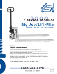
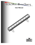
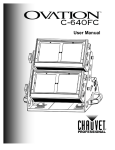
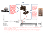
R
2000
Service Manual
Big Joe/Lift-Rite
Models: L-50 and L-50 CHEP (4 way)
Developed by
Generic Parts Service
This manual is intended for basic service and maintenance of the Big Joe/Lift-Rite pallet jack.
The pallet jacks you are servicing are tools that make moving products easier. Operating pallet jacks with rusty,
broken or worn parts makes usage and maintenance more difficult.
Pallet jack parts are inexpensive and easy to replace. To ensure maximum life from the jack, always replace the
parts that are broken or worn. Remember that all parts on a pallet jack depend on the adjoining parts to work
properly and to perform to their full potential. When used in conjunction with our catalog, this service manual will
explain how and when to replace a pallet jack part.
Remember, when in doubt...replace it.
If you have any questions, just call us. We make it easy!
1-800-331-0839
Fax 1-800-366-5939
US $ 19.95
CAN $ 29.95
CALL: 1-800-331-0839
GENERIC PARTS SERVICE
© GPS,
Inc.
Contents
2
3
3
4
4
5
6
7
8
9
10
11
12
12
12
13
Suggested Assemblies
Commonly Used Tools
Helpful Reminders
Axles
Bushings
Load Rollers and Load Roller Brackets
Steer Wheels and Axle
Traverse
Push Rods
Lifting Link
Handle Removal and Installation
Hydraulic Unit
Inspection
Service Hints
Removal
Installation
Diagram
Copyright © 1999 by GPS, Inc. All rights reserved.
Lift-Rite pallet jacks (all models) are products of Lift-Rite, Inc.
GENERIC PARTS SERVICE
© GPS,
Inc.
1
CALL: 1-800-331-0839
Suggested Assemblies
to Save Repair Time
• LF 10278-Super
Super Seal Kit
• LF C-10210-A-Super
Super Steel Load Roller Assembly
• LF 10236-B-A-D
Ultra-Poly Steer Wheel
• LF 10234-H-D
Heavy Duty Thrust Bearing
• LF 10210-P-A-D
Ultra-Poly Load Roller Assembly
• LF 10276-A
Handle Assembly
• LF 10210-P-A-D-Super
Super Ultra-Poly Load Roller Assembly
CALL: 1-800-331-0839
2
GENERIC PARTS SERVICE
© GPS,
Inc.
Commonly Used Tools
•
•
•
•
•
•
•
•
•
•
•
•
•
•
Hammer
Jack stand
45° Snap ring pliers (large and small)
1/2" Wrench
3/4" Wrench
7/8" Wrench
1/2" Allen wrench
1/8" Pin punch
3/16" Pin punch
1/4" Pin punch
3/8" Pin punch
Soft hammer (nylon mallet)
Anti-seize compound
Lubricant (i.e. WD40 may be necessary to remove rusted parts)
PIN PUNCH
SNAP RING PLIERS
Helpful Reminders
•
•
•
•
Never hammer directly on an axle; always use a pin punch.
Always replace old roll pins and snap rings.
Replace accessible bushings whenever the jack is disassembled.
Newer style serial numbers are 62500 and higher.
Older style serial numbers are 62499 and lower.
GENERIC PARTS SERVICE
© GPS,
Inc.
3
CALL: 1-800-331-0839
Axles
Inspection
If the axle is bent, out-of-round, or shows signs of wear, replace it. Check for worn roll pin holes. If these are
damaged or worn, replace the axle.
Bushings
Bushings are designed to wear out sooner than the mating parts. They are made of softer material and are
expendable. It is recommended that anytime the jack is torn down to a point where the bushings are
accessible, they be replaced. This will ensure longer life of the jack and will reduce the amount of downtime.
Bushings are very inexpensive and it is cost effective to change them regularly.
Inspection
If bushings are cracked, broken, egg shaped or worn more than 1/16" from the original size replace them.
Remember: If the jack is already disassembled, replace all accessible bushings.
Tip: Coating axles and bushings with anti-seize compound before installation makes maintenance easier.
CALL: 1-800-331-0839
4
GENERIC PARTS SERVICE
© GPS,
Inc.
Load Rollers and Load Roller Brackets
Inspection
Load roller - Load rollers should not have flat spots or large pieces of metal imbedded in them (i.e. tacks, nails or metal shavings).
Any chips in the wheel that keep it from rolling smoothly indicate the need for replacement. If the wheel has cracks, loose tread, or
does not turn freely, replace both wheels. Always change the wheels in pairs to reduce uneven wear. New load rollers have an
outside diameter of 3"(L-50), 2"(L-50 mini), and 1 3/4" (L-50 CHEP). If the diameter is worn more than 1/4" from its normal size,
replacement is necessary.
Load roller brackets - Inspect the brackets for cracks or wear from prolonged rubbing on the floor. Check for out-of-round
axle holes and inspect the bushings closely (see Bushing Inspection). If any of the above conditions exist, replace the brackets.
Removal
Tip: We recommend servicing one load roller assembly at a time, using the other assembly as a reference.
Load roller - Remove the nut and washer from the axle bolt. Slide the axle bolt out of the brackets and remove the load roller.
Remove the load roller axle sleeve from the load roller. (10 minutes).
Load roller bracket - Remove the load roller. With a pin punch and hammer, drive out the roll pin that fastens the pivot axle
to the frame, then drive the pivot axle out of the frame, exit roller, and brackets. Pull the push rod away from the frame and slide
the brackets off the push rod. (15 minutes)
Installation
Load roller brackets - Slide the brackets onto the push rod and insert the pivot axle through the frame, brackets and the
exit roller (the 4-way does not use an exit roller). Secure the pivot axle to the frame with its roll pin and install the load roller.
(15 minutes)
Load roller - Insert the load roller axle sleeve into the load roller and place the load roller between the brackets. Install the
axle bolt through the brackets and load roller. The use of washers differs from one style to the other. Use the diagrams below
or the other load roller bracket assembly on the jack as a reference. Secure the axle bolt with its nut. (10 minutes)
L-50 Mini
Nut
L-50
Bracket
Washer
Load Roller
Nut
Bracket
Washer
Exit Roller
Load Roller
Exit Roller
Pivo
t Ax
le
Axle Bolt
Roll Pin
Bracket
Bracket
L-50 CHEP
Nut
Bracket
Roll Pin
Axle Sleeve
Washer
Push Rod
Axle Sleeve
Washer
Axle Bolt
Push Rod
Pivo
t Ax
le
(4-way)
Washer
Pivo
t Ax
le
Load Roller
Axle Sleeve
Roll
Washer
Pin
Axle Bolt
Push Rod
Bracket
GENERIC PARTS SERVICE
© GPS,
Inc.
5
CALL: 1-800-331-0839
Steer Wheels and Axle
Inspection
Steer wheels should not have flat spots or large pieces of metal imbedded in them (i.e. tacks, nails or metal shavings).
Chips in the wheel, which keep it from rolling smoothly, indicate the need for replacement. Steer wheels should turn
freely. They should not rub the bottom of the traverse. If they do, check for the correct installation of the snap ring
under the traverse. If the wheel is worn more than 1/4" from the normal outside diameter, replacement is necessary.
Removal
Steer wheels - Turn the jack onto its side and then remove the hubcap. Remove the snap ring for the newer style,
or the roll pin for the older style, that fastens the steer wheels to the axle. (10 minutes)
Steer wheel axle - Turn the jack onto its side and remove the steer wheels. Drive out the roll pin that fastens the
axle to the stem of the hydraulic unit and slide the axle out. (15 minutes)
Installation
Steer wheel axle - Slide the axle into the stem of the hydraulic unit and fasten with its roll pin. Install the steer
wheels. (10 minutes)
Steer wheels - Slide the wheels onto the axle and secure with its fasteners (snap rings for the newer style or roll
pins for the older style). (10 minutes)
Older Style
1” I.D. Bearing
Newer Style
Washer
Washer
Bearing
25mm I.D. Bearing
Roll
Pin
Axle
Roll Pin
Bearing
Roll
Pin
Washer
Washer
Snap
Ring
Washer
Hub Cap
Axle
CALL: 1-800-331-0839
6
GENERIC PARTS SERVICE
© GPS,
Inc.
Traverse
Inspection
There are few things that can be wrong with the traverse. Wear can occur on the bearing shoulder or where the shoulder
bolts attach to the lifting link. If these areas are egg-shaped or out-of-round, replace the traverse.
Removal
Turn the jack onto its side and remove the steer wheel assembly (see Steer Wheels and Axle). Remove the snap ring under
the traverse and turn the jack upright. Be careful lowering the stem of the hydraulic unit onto the ground. Pump the jack
up to gain access to and remove the bolt that fastens the lift ram to the frame. Pull the hydraulic unit away from the
frame and out of the traverse. Remove the shoulder bolts and the traverse. (25 minutes)
Installation
Attach the traverse to the lifting link with its shoulder bolts. Slide the hydraulic unit into the traverse, with the washers
and lower thrust bearing already in position on the stem of the hydraulic unit. Position the lift ram and ball under the
A-Frame. Tighten the bolt onto the ram to secure the ram in place. Turn the jack onto its side, and install the snap ring
onto the stem of the hydraulic unit to hold the traverse in place. Install the steer wheel assembly (see Steer Wheels and
Axle). (25 minutes)
Lock Washer
Bushing
Bolt
Lifting Link
Bearing Shoulder
Traverse
Shoulder Bolt
Washer
Lower Thrust Bearing
Washer
Snap Ring
GENERIC PARTS SERVICE
© GPS,
Inc.
7
CALL: 1-800-331-0839
Push Rods
Inspection
When inspecting the push rods, look for broken or cracked welds, bends, missing roll pins and worn bushings. It is best to mark the
position of the eyebolt and nut in relation to the push rod to ensure proper adjustment during installation.
Removal
Turn the jack over so that the undercarriage is facing up. Remove the load roller brackets (see Load Roller Brackets). Loosen the nut
on the push rod and then the push rod can be threaded off of the eyebolt. The eyebolt can be removed with the push rod by using a
hammer and pin punch to drive the roll pin out of the pin that fastens the eyebolt to the lifting link. Remove the pin and the push rod.
The eye bolt can then be removed from the jack. (20 minutes)
Installation
Turn the jack over so that the undercarriage is facing up. Fasten the eyebolt to the lifting link with its pin and secure the pin with its
roll pins. Thread the nut onto the eyebolt with enough room to thread the push rod on, also. Thread the push rod onto the eyebolt until
it approximately matches the other push rod. Assemble the load roller brackets and the load roller onto the push rod. Line up the pivot
axle hole on the brackets to the axle hole on the frame. Slide the pivot axle through the frame, brackets and exit roller (if it has one).
Secure the pivot axle to the frame with its roll pin. Tighten the nut on the eyebolt against the push rod. (Note: The nut on the eyebolt
is primarily a marker for proper adjustment. It also keeps the eyebolt or push rod from spinning out of adjustment when working on
the load roller brackets or the lifting link.) It is easiest to adjust the push rod correctly if both push rod and bracket assemblies are in
a fully lowered position before installing the pivot axle.
To ensure that the push rods are adjusted correctly, pump the jack up, then place the jack into release. If both forks bottom-out at the
same time, the push rods are adjusted correctly. If one fork hits bottom before the other, it needs to be adjusted. You can either
lengthen the push rod that hit first or shorten the push rod that hit second. Loosen the nut on the eyebolt and turning the eyebolt one
way or the other to achieve the correct length. (20 minutes)
Bushings
Exit Roller
Shoulder Bolt
Pivot Axle
Lifting Link
Push Rod
Bushing
Bushing
Pin
Bracket
Roll Pin
Nut
Bushing
CALL: 1-800-331-0839
Eye Bolt
8
GENERIC PARTS SERVICE
© GPS,
Inc.
Lifting Link
Inspection
Check lifting link for out-of-round holes, cracks in welds or bent ears. If any of these conditions exist, replace the lifting link. Also look
for worn bushings, missing shoulder bolts, missing lifting link pins or the roll pins that fasten these parts to their mating parts.
Removal
Pump the jack up to make the bolt that fastens the lift ram to the frame, more accessible. Then remove the bolt. Remove the shoulder
bolts that fasten the traverse to the lifting link. Pull the hydraulic unit and traverse assembly away from the frame. Turn the frame over
so that the undercarriage is facing up. Disconnect the eyebolts from the lifting link by removing the pins that secure the two pieces
together. Drive the roll pins out that fasten the lifting link pins to the frame. Pull the lifting link pins out using vise-grips or pliers. This is
easier to do if you support the lifting link while pulling the pins out. (45 minutes)
Installation
Turn the jack over so that the undercarriage is facing up. Position the lifting link in the frame. Insert the lifting link pins and the roll pins
that fasten the lifting link pins to the frame. Attach the push rods to the lifting link by inserting the pin through the eyebolt and the ears
of the lifting link. Secure the pin with its roll pins. Turn the jack over and place the traverse and hydraulic unit assembly into position.
Insert the lift ram into the frame. Thread the shoulder bolts through the ears of the lifting link and into the traverse to secure it. Fasten
the lift ram to the frame with the bolt. (45 minutes)
Bolt
Roll Pin
Lifting Link Pin
Lock Washer
Bushings
Shoulder Bolt
Lifting Link
Push Rod
Bushing
Pin
Pin
Roll
Traverse
GENERIC PARTS SERVICE
© GPS,
Inc.
9
CALL: 1-800-331-0839
Handle Removal and Installation
Inspection
Inspect handle for cracks and structural integrity. There should be minimal side play in the handle socket. Check for worn bushings. If
bushings are not replaced regularly, the handle bracket holes can become worn. Damaged holes cause pin failure and may require complete
handle replacement. Also inspect the roller for flat areas and wear. If any of the above parts are worn more than 1/16", replace them.
Removal
Loosen adjustment nut on lower control rod, and slide the control rod off the release lever. Remove the shoulder bolts from the handle
bracket, and the handle is now ready to come off. (10 minutes)
Installation
Set the handle on the hydraulic unit. The roller should be placed on top of the pump piston. Push down on the handle to compress the spring
under the pump piston. Line up the holes and install the shoulder bolts.
(Tip: You may need someone to help you hold the handle in place in order to keep the pump piston compressed while you install the shoulder
bolts.) Insert the lower control rod into the release lever and tighten the adjustment nut. (15 minutes)
Control Rod
Adjustment
Hold the release lever up and insert the lower control rod, with the adjusting nut already on it, into
the slot of the release lever. Place the control lever
into raise mode and pump the handle. The jack
should rise. If it doesn't lift, unthread the adjusting
nut until pumping the handle raises the jack.
Place the control lever into neutral mode and pump
the handle. The jack should not lift. If it does, the
adjusting nut needs to be tightened until the jack
no longer rises. If the jack lowers when the control
lever is placed in neutral, the adjusting nut needs
to be loosened until the jack stops lowering.
Place the control lever into release mode and the
jack should lower. If not, the adjusting nut needs
to be tightened.
(10 minutes)
Control Lever
Pump Piston
Spring
Control Rod
Bolt
Lock Washer
Pin
Chain
Adjustment
Nut
Roller
Bushing
Shoulder Bolt
Release
Lever
CALL: 1-800-331-0839
10
GENERIC PARTS SERVICE
© GPS,
Inc.
Hydraulic Unit
Inspection
Inspect the outside of the pump for oil leaks. Test the unit, under a load, to determine if there is a problem. This can be done by
lifting a heavy pallet and letting it stand for 15-20 minutes. Below are symptoms and solutions to common hydraulic unit failures. If
the following solutions fail to correct the problem, a complete rebuild of the malfunctioning unit may be necessary. Please refer to
our catalog for information about ordering the appropriate seal kit or take advantage of our hydraulic unit exchange program.
Jack fails to lift load
• Air Lock in Pump - Place the control lever into release position, then pump the handle rapidly about 10-15 times. (5 minutes)
• Low Fluid Level - With the jack in a lowered position, remove filler plug. Using UNI-HO oil, fill the reservoir until the oil is
level with the fill plug hole. Bleed the unit (see Air Lock in Pump). Replace the filler plug, creating a snug fit. Do not over-tighten.
(5 minutes)
• Hand Control Out of Adjustment - See Control Rod Adjustment under section heading Handle Removal and Installation.
(10 minutes)
Jack fails to lower
• Look for any bent frame parts (lifting link, push rod, etc.). Bent frame parts need to be replaced.
• The hand control may be out of adjustment (see Control Rod Adjustment under section heading Handle Removal and Installation).
• Debris blocking an oil channel in the hydraulic unit. Contact us for our hydraulic core exchange program.
Jack lifts in short increments
• Lack of oil pressure - see to Low Fluid Level.
• Reservoir filler plug leaking - Replace the washer and filler plug and replenish oil, if necessary
(see to Low Fluid Level).
One fork lifts, the other does not
Check for damage in the following areas and their attached parts:
• Lifting link (lifting link pin and traverse shoulder pin)
• Pushrod
• Load roller bracket (pivot axle)
GENERIC PARTS SERVICE
© GPS,
Inc.
11
CALL: 1-800-331-0839
Hydraulic Unit
Service Hints
• Tampering and abuse are two of the most common problems. In most cases, minor repairs become major when
inexperienced people attempt to rebuild a hydraulic unit. If you come across a unit that looks like it has been
tampered with or modified, inspect the unit carefully to be sure it can be rebuilt or call Generic Parts Service for
technical assistance.
• The ram is chromed and the pump piston polished to a fine finish for maximum seal life and minimum oil
leakage. If you see these surfaces nicked or pitted, this will cause the unit to fail in a short time. Replace any
rusty or damaged parts that will cause premature wear on their mating parts or the body of the hydraulic unit.
• Use UNI-HO hydraulic oil.
Do not use automotive oil or hydraulic brake fluid.
Removal
Pump the jack to its maximum height and turn the jack onto its side. Remove the steer wheels and axle (see Steer
Wheels and Axle Removal) and the snap ring under the traverse on the stem of the hydraulic unit. Turn the jack
upright; be careful no to damage the stem of the hydraulic unit while lowering. Remove the bolt that fastens the
top of the ram to the frame. Lift the frame off of the ram, tip the handle and hydraulic unit away from the frame,
and rest both pieces on the ground. Remove the ball on top of the ram and pull the hydraulic unit out of the
traverse. Remove the handle and handle bracket, if necessary (see Handle Removal). (45 minutes)
Installation
Slide the stem of the hydraulic unit into the traverse with the traverse bearing already in place on the stem. Insert
the ram into the A-Frame with the ball positioned on the top of the ram and secure the ram to the
A-Frame with the bolt. Carefully turn the jack onto its side, keeping the hydraulic unit in the traverse and frame.
Attach the snap ring to the stem of the hydraulic unit under the traverse. Install the steer wheel assembly (see
Steer Wheel and Axle Installation) and the handle, if necessary (see Handle Installation). Bleed the hydraulic unit
(see Air Lock and Pump). (45 minutes)
CALL: 1-800-331-0839
12
GENERIC PARTS SERVICE
© GPS,
Inc.
Hydraulic Unit Diagram
Ball
Pump Piston
Ram
Bolt
Lock Washer
Control
Rod
Filler Plug
Washer
Adjusting
Nut
Release
Lever
Note:
Newer style jacks have a recess on the top of the
traverse which requires a spacer. Models with the
older style traverse do not require this part.
Washer
Traverse Bearing
Washer
Traverse
Snap Ring
GENERIC PARTS SERVICE
© GPS,
Inc.
13
CALL: 1-800-331-0839