1
The
DUO-ART
Reproducing Piano
,
,.,
DI/o-A rt Service Department
The AEOLIAN COMPANY
Aeolian Hall
NEW YORK
INTRODUCTION
The object of this pamphlet is to give a clear and concise
working knowledge of the Duo-Art Pianola Piano. It is obvious
that in these few pages the aforementioned SUbjects will have to
be treated briefly, and that a great deal necessarily will have to
be taken for granted that the mechanic already knows, such as a
general knowledge of pneumatics, and something of electricity.
There is nothing really complicated or intr;'icate about the
Duo-Art and once its principles are understood it will be realized
what a truly remarkable yet simple instrument it is. These
instructions are based upon the upright Duo-Art but would apply
generally to the Grand as it differs only in design.
OPERATION OF DUO-ART DYNAMIC CONTROL
The above subject will be treated under four sub-headings,
namely:
1.
Dynamic Step Control
2.
Accompaniment Control
3.
Theme Control
4.
Manual Control
DYNAMIC STEP CONTROL
The Duo-Art dynamic control has 15 steps or degrees of
loudness, and with the fundamental or zero degree, sixteen.
By zero degree is meant the normai Duo·Art. The zero degree
is not called a step. To put it simply, it is the foundation or baSIS
upon which all the higher degr~es are built. As will be explained
later in the Duo·Art test, this zero degree should be as low or
soft, as possible.
The 15 steps are controlled by four holes in the tracker bar
at both the treble and bass ends of bar, above the regular piano
notes. (which are inoperative with the Duo-Art lever "ON") The
four holes at bass end of bar control the accompaniment side of
the expression box and the four in the treble end control the
theme side of the box, in conjunction with additional holes in
the bar (B Theme & T Theme - see diagram No.1 I.
These holes in both bass and treble are numbered from the
outside in (see diagram no. 1) Nos. 1, 2, 4, 8. It will be noticed
that each number is double its predecessor and that IS exactly
what they are in dynamiC power. From the tracker bar, these
dynamic control tubes lead through two cut-off pouch blocks,
(see diagram no. 2, no. 4) and from there to dynamic valve box,
(no. 281 which controls the accord ian dynamics (nos. 26, 27).
Each of these accordian dynamics has four small pneumatics,
each set to collapse a certain distance by small adjusting screws.
Number one in both accompaniment and theme controls the
top or smallest pneumatic of the four and collapses 1/16".
Number two on each side controls the next pneumatic and
collapses 1/8".
Number four on each side controls the next pneumatic and
collapses 1/4".
Number eight on each side controls the bottom, or largest,
pneumat ic and collapses 1/2".
This makes a total, with all collapsed, of 15116". These pneu·
matics can work separately or in combinations, or all together.
There are 15 combinations possible with these dynamics.
COMBINATIONS
Step 1.
Step 2.
Step 3.
Step 4.
Step 5.
Step 6.
Step 7.
Step 8.
Step 9.
Step 10.
Step 11.
Step 12.
Step 13.
Step 14.
Step 15.
Number
Number
Number
Number
1
2
4
8
Valves open
NO.1
Valves open
NO.2
Valves open
No.2 Valves open,
NO.4
Valves open
. _No.4 Valves open
NO.4 Valves open
No.4 Valves open
No.8
Valves open
No.8 Valves open
No.8 Valves open
NO.8 Valves open
NO.8 Valves open
NO.8 Valves open
No.8 Valves open
NO.8 collapses 1/16 inch
collapses 1/8 inch
collapses 1/4 inch
collapses 112 inch
Total collapse, 15/16 inch.
It will be observed that the accordian dynamics are connected
by a rod at the top of the dynamics to an arm, which when pulled
down opens a knife valve (see nos. 16, 17\. These knife valves
operate over port holes leading to the pump, and the degree to
which these holes are opened determines the loudness of the
playing. The Duo-Art normally is under low pump tension,
drawing in the atmosphere through a spill valve (see no. 18)
'.and exhausting through the pump. This spill valve is completely
cut off by either the accompaniment or theme dynamics at the
10th step. Note connection of spill valve to both the accompaniment and theme sides of expression box, and as either knife
valve is pulled down, or opened, by dynamics, they push against
rocker arms mounted on a shaft at the back of the expression
box and the knife valve closes off the intake, or what is termed
"spill".
ACCOMPANIMENT CONTROL
A very important feature of the Duo-Art dynamic control is
that either the accompaniment or theme side of the expression
box can control the entire keyboard, or one can control the bass
while the other controls the treble, or vice versa. This gives great
flexibility of control and the advantages of such a system are
innumerable. This is a feature found only in the Duo-Art. The
regular player action is divided between the 43rd & 44th notes.
The air is exhausted from player action into chambers Nos.
6 & 8 of expression box, through flap valves Nos. 9 & 10 into
chamber 7, and down through channel 14 into accompaniment
regulator. Here is passes through knife valve 16 and along channel to pump where It is exhausted.
The theme secondary valves (11 & 12) are normally closed.
As has been explained, the degree to which knife valve in
the accompaniment regulator is opened determines the loudness
of the playing.
THEME CONTROL
The theme dynamics (No. 27) control the degree with which
accented notes are struck, but it is the valves (11 & 12) which
are controlled by holes in tracker (marked B theme & T theme)
operating theme primary valves (5) that determine when theme
shall operate.
The air IS exhausted from player action Into chambers (6 & 8)
of expression box. Now theme control holes in tracker bar are
opened admlttrng atmosphere to pouches under primary valves
(5) raislllg them, and putting secondary valves (11 & 12) under
suct lon, causing them to drop and making a passage for air to
channel 13 where it follows to passage 15 into theme regulator.
Here It passes through knife valve (17) and into channel leading
to the pump, where it is exhausted.
-Showing how accompaniment side can control the treble
while theme side controls the bass, or vice versa.ACCOMPANIMENT CONTROL OF TREBLE
The air comes into chamber (8) from player action, and theme
valve (12) being closed, passes through flap valve (101 into
chamber (7) through channel (14) Into accompaniment reg·
ulator, through knife valve (16) and to the pump.
THEME CONTROL OF BASS
1
1
2
2 - 1
1
2
2
4
4
4
4
- 1
- 1
- 2
- 2 - 1
Arr comes into the chamber (6) from player action and theme
valve (11) being open due to bass theme hole in tracker being
opened, the air passes into channel 13 and then through passage 15 into theme regulator, on through knife valve 17, and
to the pump. It should be understood that the air once III chamber 7 cannot return to chambers 6 & 8. A study of the flap
valves 9 & 10 will be self-explanatory.
MANUAL CONTROL
Other remarkagle features of the Duo-Art Pianol:J P,ano are
the devices for its manual contro!. This system is equalled by
few, if any. and surpassed by none. ThiS system is controlled by
five levers, four of which are in front of the keys and one In the
spool box.
The first lever on key front to the left is called the theme
modulating lever. This lever controls the degree at which theme
notes are played, but unless worked in conjunction with the two
little levers on the key front next to the right, one above the
other, there is no noticeable result. As will be noticed in the diagram, the theme modulating lever is connected to the theme
knife valve regulator, and as the lever is pushed to the right, it
pulls down and opens knife valve (17) but as long as valves 11
& 12 are closed, it has no effect.
These two levers to the right, one above the other, control
theme primary valves (5). The topmost one controls the bass,
and the bottom one, the treble. The modulating lever controls
the degree, and these bass and treble levers, the time, when the
theme shall operate.
The next lever is called the Temponamic Lever. This controls
the tempo by its side motion, and accompaniment expression
by its rotating motion.
By turning this disc to the right, it pulls down on arm, regulating the knife valve, and opens a port leading to the pump.
The more this port is opened, the louder the playing.
The fifth control is the Duo·Art lever in the spool box. This
lever should be in the "Duo-Art ON" position for all Duo-Art
rolls to be played automatically. To play Duo-Art rolls with
personal expression, have this lever in the central position. For
all other 88·note rolls, have this lever at "OFF".
When the Duo-Art lever is thrown to the center, or neutral
position (or to the OF F position) the little pneumatic (25)
collapses to the point adjusted to by the screw in the moveable
board of t he pneumatic and pulls down on the arm controlling
the accompaniment knife valve, thus making the zero degree
louder when the Duo-Art lever is at "OFF". It has no other
function.
HOW TO TEST AND ADJUST THE DUO-ART
This test will be in a series of steps (12 in number) and will
cover all points necessary far a thorough inspection and adJustment of the instrument.
STEPS IN TEST
Step
Step
Step
Step
Step
Step
Step
Step
Step
Step
Step
Step
1.
2.
3
4
5.
6.
7.
8.
9.
10
11.
12.
Tracker box gearing and connections.
Electric motor, pump, and connections.
Tracking device.
Tempo.
Sustaining pedal.
Soft pedal. (Hammer-rail liftl
Dynamics.
Accompaniment zero setting.
Theme zero setting.
Notes.
Dynamic Chord test.
Re-roll.
IMPORTANT
Before beginning the Duo-Art test, it is advisable to see that
the piano action is properly adjusted, and a few words here on
that subject would not be out of place.
As is well known, all piano actions are more or less affected
by extreme dampness or by dry weather, which tends to alter
their regulation, thereby making it difficult for the player to
function properly.
Push the hammer rail toward the strings and let it back
quickly. If the hamme~ are slow in returning, the action is damp
and swollen, and must be remedied before going further.
See that there is no lost motion in jacks. See that the hammer
escapement (let-off) is properly adjusted; it should average 1/8"
or less from the strings. Now see that the hammers check about
5/8" from the strings.
These are the most essential adjustments in relation to the
player action and under no circumstances should they be overlooked. The more the mechanic knows of piano action regulation
the finer results he can get from the player action. Now see that
there is no lost motion between the player action pitmans and
the wippens on the piano action. See that the stroke on the player is the same as the hammer check on the piano action. This is
a common adjustment to all player actions and need not be explained here. Make sure player action is screwed fast; all tubes
are secure, rods connected, and working freely.
SPOOL BOX GEARING AND CONNECTIONS
Step 1.
See that the gearing is properly oiled, and all set screws
tightened.;
Set the re-roll and play brakes.;
See that the sprocket chains are not too loose nor tight.
Have all parts on wind motor free but not noisy. Use no
oil on the wind motor.
Pump out tracker bar and insert test rolLin spool box.
-~
ELECTRIC MOTOR, PUMP AND CONNECTIOrzS
Step 2.
"
Connect electric cord to conduit in back of piano and make
sure the current is on.
Be sure the motor is proper for local current.
Have motor hand level and with enough tension on belts so
that they will not slip.
See that motor is properly lubricated and set screw in the
pulley is tight.
See that the armature on the motor rotates freely.
Now turn on switch - if motor does not start instantly,
turn off switch or motor will burn out.
Notes on Duo-Art Motors
There are two types of motors used; 1/4 horsepower motor
being used with the six feeder type pump, and 1/8 horsepower
with the four feeder pump. Both motors run at 1150 rpm in
both AD and DC models.
All AC motors are 60 cycle.
To change rotation of DC motors, reverse leads at brush box.
To change rotation of AC motors interchange two leads
coming through bushing cover.
(Step 2 continued}
A fter motor has been inspected, have idler on pump belts
set reasonably tight and on slack side of belts. Now see that
grease cups on pump are filled and turn plungers down a bit to
force grease into bearings. Have pump quiet and time pulsations.
A pulsation is the opening and closing once, of one feeder.
Six feeder type pump should pulse 70 - 72 times per minute,
and the four feeder type 120 times per minute.
To change speed either way it would be necessary to change
the size of pulley on motor. Duo-Art motors are furnished with
proper size pulley to give required pulsations, and before any
change of pulley is made, it would be advisable to make certain
that the voltage of current supplied is correct. TRACKING DEVICE
Step 3.
Make sure your test roll measures eleven and one quarter
inches in width. If not, use a roll that does. Have music spool
shaft in center of shifting cam and shifting pneumatics centered.
These are adjusted on shifting rod at back and left of spool box,
by a small turnbuckle. Now with roll running, adjust tracker lugs
so that they just barely touch the edge of the roll.
TEMPO
DUO-ART LEVER "OFF"
Step 4.
Follow tests on roll in rotation. With tempo indicator at 70,
roll should run seven feet per minute. Tempo should cut off
with indicator at extreme left and just start at ten. To run
faster, tighten spring on governor; to run slower, weaken spring.
SUSTAINING PEDAL
Step 5.
The sustaining pedal is controlled by second hole in bass end
of tracker bar. Flat dampers should clear strings about 1/8"
with pedal on. Dampers should come back to strings between
each bridge in the test roll with tempo set at 70.
It will be noticed that the sustaining pedal, soft pedal and
dynamics get their supply from a pneumatic tension regulator.
This regulator keeps their supply under even tension. This is
done by a spring attached to it. Adjust spring so that pedals
and dynamics work quickly but not noisily. To operate faster,
strengthen spring; slower, weaken spring.
SOFT PEDAL
Step 6.
The soft pedal is contrOlled by the last hole in the treble end
of the tracker. On uprights, rail should move to 1/8" from the
strings. On grands, rail should lift 5/8 from normal position.
DYNAMICS
Step 7.
In making this adjustment always get a blank setting on the
test roll, have motor running and tempo cut off. Watch accompaniment regulator pneumatic while setting screw; softening
causes it to open and the reverse causes it to collapse. Adjustment can be gauged accordingly. Patience is required in making
this adjustment, but with a little practice it comes readily. As
will be observed, knife valve has to be adjusted to take first run
of notes softly, but skip or miss most of notes on second run.
ACCOMPANIMENT (Duo-Art lever "ON'"
The accompaniment dynamics are operated from the bass
end of tracker bar, above ordinary piano notes, and are numbered
1,2.4,8. These dynamics should operate in order given.
THEME
These dynamics are operated by four holes in the treble end
of tracker bar above piano notes and are the same as accompaniment dynamics, 1,2,4,8, and should operate- in order given.
ACCOMPANIMENT SETTING OF ZERO DYNAMIC
Step 8.
Tempo at 80
TO SET SOLO OR THEME DYNAMIC
Step 9.
The theme adjustment is made on adjusting screw similar to
accompaniment side (see No. 20) It also has a set screw (20-a)
which must be loosened while adjusting screw is being set, and
tightened immediately
The setting of theme side is dependent upon the setting of
the accompaniment as no matter where the latter is set, theme
must be one degree louder. Naturally, the conception of "one
degree" will vary with the individual, but a uniformly safe rule
to follow IS to have the theme regulator pneumatic collapse 1/8"
more than the accompaniment pneumatic. Never have theme
pneumatic even with, nor opened more, than accompaniment.
Warning:
This is the most delicate and Important adjustment in the
entire test and great care must be taken in this adjustment. On
its setting depends the ability of the instrument to play the soft
runs and trills in the music so much desired by all music lovers.
First throw off electric switch and see that regulator springs
(21 & 22) have a little tension, just enough to keep them from
rattling. Use adjusting rings (23 & 241. Now see that all tension
springs on the expression box have a little tension on them. See
that the rocker arms controlling spill valve when pushed back
move forward again quickly. Also have arms regulating knife
valves come back quickly.
Have all rods and shafts on expression box free from bindll1g
and squeaking. A very important thing to watch is that there is
no pressure against knife valve regulating arms, otherwise the
knife valves would open a little and this would make it impossible to properly adjust zero dynamics. Also, there should be no
slack in arms resting on knife valve regulators as this is just as
bad as the previous condition mentioned. The little leather
adjusting nuts on top of accordion dynamics (26 & 27) on rod
to knife valves should not be tampered with as they are set
properly at the factory and seldom if ever need resetting. If the
accordion pneumatics have a little slack or sag, from leather
stretching, it is permissible to take this up on these leather
nuts, being careful not to put too much tension on the rod as
this will open knife valve and this adjustment must be made
before sett ing accompaniment Or theme regulators as it will
throw out their setting if done after they are adjusted. It is,
however, rare that these nuts will need any adjustment.
Throw on electric switch and observe sottness of notes on
accompaniment tests. It will be noticed that sustaining pedal is
on with the first run of notes, making them easier to play and
off with the next run. Notes should play very softly and on the
next run should miss most at them, Or strike an occasional
note. The third run of accompaniment test is similar to the
first.. If on the second run of ndtes'io accompaniment setting at
zero dynamic all notes strike full, playing IS too loud and must
be softened. To soften, adjustment is made on knife valve adjusting screw (19) and next to this adjusting screw is a small set
screw (19-a). This must be loosened before trying to turn adjust·
ing screw or thread will be stripped. Immediately after adjusting
screw is set, tighten lock screw as there 'is a little play in knife
valve shaft unless this is tightened and it would be impossible
with lock screws loose to make fine adjustment.
On uprights, to soften, turn adjusting screws to left, and to
the right to make louder.
On grands it is just the reverse, as the expression boxes are
installed just the opposite way. It takes only a slight turn of the
adjusting screw to make a great difference.
NOTES
Step 10.
Notes should all strike evenly and softly on thiS test. We will
not go into a discussion here of the ordinary note troubles as
the mechanic is unquestionably able to handle any trouble arising with them.
DYNAMICS CHORD TEST
Step 11.
These chord tests show if dynamics build up evenly. It
accompaniment setting of zero dynamic was properly adjusted,
the first three chord tests will be found very near right. A slight
adjustment on the regulator springs 121 & 221 is permissible,
but any radical adjustment will throw accompaniment setting
of zero dynamic out, and care must be taken to avoid this.
It may be necessary to meet chord tests to reset accompaniment
and theme zero dynamics a little, The last eight chord tests
show evenness of dynamics in building up, and if pump has been
properly tested and all adjustments made correctly up to this
point, instrument shoVld meet these test.
Followll1g on the" lest roll are two selections of music especially selected to tryout the responsiveness of the dynamic
mechanism.
RE-ROLL
Step 12.
The re-roll IS operated by the first hole in the bass end of
the tracker bar, and throws the gearing into reverse and cuts off
air to action slide valve (291.
If slide valve (29) did not completely cover the port on reroll, the plano would play in the re-roll mode. This seldom
happens, but It is possible. The mechanic should always remember ,In locating trouble that there is only one sure m,nhod to
follow without tearing everything to pieces, and that is to locate the trouble by a process of elimi'nation.
I
I
~
I
,
,_
__
-~-~
,.....
I
,;{-
'--i. ->-v
~
~ 0]'11"",""'.JJ.\\.......~
""",,~ ,I
I
\
I,
......
........
'~,~,'
I
I
~,,~
.............. 1/
L _ .',-
"'
I
A..'~
I
1
.
I
"' \
.. <<<<<
I
J
-
II
"-
.........
............ ........
I'-ll
"""-:"':::::.
--- ----
~r/
--11'
I
II
II
I
'I
II
II
I
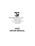
tF t DYNAMIC COLLAPSES
#2
#4
#8
• I
••
••
••
••
••
I
I
liVSTRLlCT/O"VS FOR /ICCO/\1P"4/vTI!Hf~NT XERV SETTiNG
First see that dynamic lever, on extreme left of keyboard, is on normal. All dynamics should be open.
Loosen lock screw by turning to the left. Start piano and turn regulating screw to the right to make
"soft" to the left "loud" on the GRAND. On the UPRIGHT piano to the left to make "soft" to the
right "loud." When regulation is completed tighten lock screw by turning to the right locking zero
settmg.
M~nuaj
N,). 3.
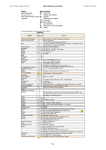
ACCOMPANIMENT AND l"'HEME ZERO SETTING ADJUS'"'MENT
'.
O~
O~
0::
0.,
0::
O~
0:1: Olsl
Of: O~
O~ (J'I!
O't 0:
0;: 0'.:
O;! ~
o~
Oil
O. 0 ..
0", 0':::
O~ 0;::
Ocr 0"
0"
'"
0'" 0 ...
.
........ uuu
'.-p
"'."',,:»
• • • "" It It M ~
....... .lvO
7.".' ""'''1 tIl.
i
~ ~
000
"l~ W
., .....
"'00
~I
I
.,,,.,.,,,
""a-e-'i-t~
~
. J.~-~;N7i
....
0000
~
'~
),.
......
:8~~d
". '1'11&1
lloij
0
----
~·~U9I7·
~v-".iS:-~:i.i~;";#d..
".,,,.
:~I
IC.4.,
'--------y~~
. . ri7,.;i """,""''''/'1
-Jii'~"I'J.*"" ....,~
.--
:'lll
I
~~
I
Jc
:~I
~
@
~l
~'i
'"I
~
-
The Duo-Art
Editor: Included in Wilberton Gould's series
in The Tuners' Journal on "Player Piano Mechanisms" is the following article on the servicing
of the Duo-Art.
Mr. Gould makes extensive reference to the
1927 Duo-Art Service Manual in this discussion,. especially to Illustration "E" therein.
Illustrations and sections to which he refersincluding Illustration "E"-are reproduced at the
end of this section on the Duo-Art.
THE DUO-ART
In the servicing of the Duo-Art mechanism,
it is absolutely necessary that the technician
understand the expression system and the principle under which it functions. The only tools
required are a screwdriver, a Duo-Art test roll,
and a musical ear. The mention of this last item
might seem out of place in this technical series,
but experience has proven it to be vital.
The expression box is the heart of the DuoArt, through which the artist's musical thoughts
may be reproduced, and it will be discussed thoroughly here. All references made to the expression box apply both to the grand and to the
upright models, with one exception; this exception is referrred to irr The 1927 Duo-Art Service
Manual, and will be discussed later.
The adjustment of the various degrees of shading in the Duo-Art must be approached from a
musical standpoint if effective results are to be
achieved. Assuming, of course, that mechanical
conditions are equal, it is possible through the
unique dynamic control to control the entire
register of the instrument either by the accompaniment regulator or the solo regulator.
The keyboard of the instrument is divided
musically into theme, or solo, and accompaniment in the same manner as if it were played
man-(or Ms.)-ually. For example, carrying the
melody from the bass to the treble, or crossing
the hands, or carrying the melody from the treble
into the bass, is effected through the accompaniment regulator or the theme regulator. There
is no duplicate control system in the Duo-Art,
a control system for the bass and one for the
treble. On the contrary, one regulator, either the
accompaniment or the theme in conjunction
with the theme valves, may control the entire
register. In order to understand how this is accomplished, it is necessary to understand the
travel of atmosphere from the pneumatic stack
to and through the expression box and also to
know what is taking place during the operation.
Referring to the phantom view on page 17 of
The 1927 Service Manual (illustration "E").
it will be noted that figures 19 and 25 are the
main supply from the pneumatic stack to the
expression box-bass and treble ends. Under
normal conditions, when the theme secondary
valves (figures 16 and 27) are up against their
top seats, they cut off air channels from chambers
20 and 24. This causes the atmosphere entering
the nipples (figures 19 and 25) from the pneumatic stack to enter the accompaniment chamber
(figure 22) and pass down, as indicated by the
arrows, into the accompaniment regulator,
through the knife valve port and thence to the
pump. By this it will be seen that air travel is
through the accompaniment regulator, as long
as the theme secondary valves remain against
their upper seats, thus proving that normally the
instrument is under accompaniment control.
The degree to which the strength of the blow
is governed by the movement of the knife valve
is controlled by means of the accordion pneumatics 6, 5, 4, 3, 31, 32, 33, and 34 in conjunction with the theme secondary valves 16 and
27. The collapsing travel of the accordion pneumatics being 1/16th, 1/8th, 1/4th, and 1/2
inches, as these accordion penumatics collapse
The Duo-Art - continued
It will be noted that the note holes start at
the fourth hole from the bass end and the fourth
hole from the treble end, reading from the outer
edge toward the middle, the first speaking note
is No. 5 and the last is No. 84, making eighty
speaking notes. This applies to the later type
Duo-Art mechanisms. In the earlier models, the
speaking scale is full eighty-eight notes on straight
eight-eight note rolls, but still remains eighty
speaking notes on the Duo-Art reproduction.
they control the opening of the knife valve port.
The greater the area of the knife valve port the
stronger the blow given.
There are adjusting screws on the cross bars
of the accordion pneumatics. These should not
be disturbed, as they are set correctly at the
factory and should be adjusted only by a set
of accurate gauge blocks that are made for that
purpose. It is also necessary that the~e_ be just
enough tension on the springs to bring the accordion pneumatics back to rest snappily, with
not tOe;> much or too little tension. Care should
be exercised in this operation; if there is too
little tension, the accordions will not come to
rest quickly enough, and if there is too much'
tension, the accordions will Jag in their collapsing, with the result that the knife valve will
not open enough, as it should. Likewise, the
tension springs on the regulators should not be
drawn down to a greater degree than is necessary, but should be just taut enough that they
do not rattle. Pulling down the tension springs
on the regulators is frequently done because of
lack of knowledge. When this is done, it upsets
the zero setting of the regulators (Editor: also
read "Steps in Test No.8"). If this operation
is carried to the extreme, it will ruin the springs
for the fine setting of the accompaniment or the
theme and it will be impossible to bring down the
tone to that softness so much desired by real
music lovers. If the springs have been ruined,
the only remedy is new springs. Therefore, it
is suggested that a player technician tread very
softly along this path. Editor: If new springs
are being installed, it is very important that the
correct tension, size, and gauge of the new
springs be established before they are replaced.
Note holes 1, 2, 3, and 4 at the bass end and
85, 86, 87, and 88 at the treble end have each
directly above them a perpendicular oblong
port. These oblong ports are the accordion dynamic control ports and are connected by tubing
to the Duo-Art cut-out pouch blocks directly
behind the spool box. These blocks contain a
series of four pouches on either side of the
blocks, one on the bass end and the other on the
treble end, and are connected to the supply from
the Duo-Art cut-out block on the left-hand end of
the spool box; they are marked"Duo-Art On"
and "Duo-Art Off." With the Duo-Art lever at
the "On" position, atmosphere is admitted to
the top side of the note pouches on the blocks
marked 1,2,3,4 notes and 85, 86, 87, 88 notes;
this inflates the pouches' and cuts off the note
holes from the tracker bar. With the Duo-Art
switch at the "On" position, atmosphere is admitted through anyone of the accordion dynamic
control ports above the note ports, passes through
the pouch cut-out block, thence to the accordion
primary valve box, from there to each of its
respective primary valves, then to each of the
accordion dynamic pneumatics on the expression
box. In the upright model, the dynamic valve
box is assembled on the expression box frame.
In the grand model, it is attached to the frame of
the case as closely as possible.
Before going further into the expression box,
the expression control ports on the tracker bar
should be explained, so that they may be better
understood when referring to the expression
box.
The therre valve ports on the tracker bar lead
to the theme primary valve box (valves Nos.
29 and 30) and there to the theme secondaries
in the expression box. (See figures 17 and 18
in Illustration "E. ")
Referring to Illustration "E" in The 1927
Duo-Art Service Manual, we find the following:
Re-roll
Sustaining Pedal
Bass Theme
No. I Dynamic Accompaniment
No.2
No.4
No.8
The re-roll port and the port in the take-up
spool lead directly to the repeat and re-roll primary valve box underneath the key bed. These
valves control the re-roll and repeat pneumatics
In the upright model, the tube leading from the
switch cut-out, or motor port, goes to the left
and passes through the repeat slide block where
if the slide block is in the off position, it con-
Soft Pedal
Electric Cut-Off
Treble Theme
No. I Treble Theme
No.2
No.4
No.8
2
The Duo-Art - continued
tracker box. Under normal conditions, the
valves in this box are at rest, or down against
their bottom seats. Atmosphere is admitted
over the tops of the valves, passes through
connecting tubes and inflates the pouches under
the secondary valves, thus holding these secodary valves tightly against their upper seats and
preventing any passage of air from the pneumatic stack to the theme regulator. The inflation of the theme secondary pouches just mentioned is accomplished by the action of the
theme regulator suction which entirely surrounds the top surfaces of both theme secondary pouches. The moment theme perforations
appear on the music roll, atmosphere is admitted
through the theme ports in the tracker bar to
the primary pouches, inflating them and raising
the primary valves to their upper seats. This
action cuts off the atmosphere which was admitted through the top cups and permits the
suction of the theme primary box to exhaust the
secondary valve pouches through the bottom
cups, causing the secondary valves to drop and
thus momentarily open a channel between the
pneumatic stack and theme regulator. The
opening of this channel is the action whereby
the air from the pneumatic stack is changed
from the accompaniment regulator to the
theme regulator.
nects with the tube leading to the switch valve
box (figure 8, lllustration "0" in the 1927
Duo-Art Service Manual).
The sustaining pedal port-Editor: .also known
as the loud pedal port -on the tracker bar leads
directly to the sustaining pneumatic in the
grand type and to the pedal regulator in the upright model. The soft pedal port leads to the
soft pedal primary valve box in the grand model
and to the pedal regulator in the" upright model.
In the later types of Duo-Art grands, the shifting
of the action is accomplished by atmosphere
being admitted through the soft pedal port
in the tracker bar. The raising of the hammer
rail is accomplished by placing the ~odulat
ing lever, on the control slip, in the soft position.
We will now show how the air travel is changed
within the expression box when a theme perfora·
tion appears on the music roll and what happens
when this takes place.
Referring to the phantom view on page 17
of the Duo-Art Service Manual, figures 16 and
27 are the bass and treble theme secondary
valves. Editor: The author is referring to fllustration HE" on page 17 of the 1927 Duo-Art
Service Manual.
The same reference may be
found in the 1925 Duo-Art Service Manual, fllustration "B," figures 20 and 30. Also, on the
diagram that is part of the Duo-Art Preliminary
Instruction Pamphlet, the same reference is
figures 11 and 12. They are controlled through
the bass and treble theme primary valves located
in the valve box on the top action, at the left of
the tracker box. The theme primary valve box is
shown at the right of the expression box on page
17. Figures 29 and 30 are the bass and treble
theme valves respectively and are connected to the
secondary valves in the expression box and to the
tracker bar. As previously stated, under normal
conditions the theme secondary valves are against
their top seats, thus compelling the atmosphere
from the pneumatic stack to travel through chambers 20 and 24, through the flap valves 21 and 23,
into chamber 22, down through the channel, as
indicated by the arrows and through the knife
valve port of the accompaniment regulator and
to the pump.
The moment one or both of the theme
secondary valves drop, since the theme regulator
suction is usually of a higher intensity than
that of the accompaniment regulator, this
stronger suction will draw the flap valves (21
and 23) to their seats and cut off channel 22
from the pneumatic stack. Thus, momentarily, the stack may be entirely cut off from the
accompaniment regulator. "This occurs only
when the stack is opened to the theme regulator. When this occurs, the air from the stack
entering chambers 20 and 24 will pass down
and over the theme secondary valves and into
the channel underneath and directly behind the
accompaniment channel (this channel is shown
but is not numbered on the phantom view, but
is indicated by the arrows from the theme
secondaries), through the port shown leading
into the theme regulator, and there to the pump
and exhaust.
This condition can happen collectively or
singly, as the case may be, according to the
perforations on the music roll. The strength of
the blow is governed by. the movement of the
k.nife valve within each of the regulators. This
The question may arise: How do the secondary valves remain seated against their top seats?
As stated above, there is a theme primary valv.e
box located on the top action at the left of the
3
The Duo-Art - continued
out any single note in either the accompaniment or the theme and accent it at will.
This follows the same principle as the expression perforations cut in the Duo-Art
music rolls.
movement is controlled by the collapse of the
accordion dynamics, The theme valves determine the note or notes that are to be accented
by accenting any note or group of notes whenever a direct passage is opened through the
theme regulator to the pump.
The spill valve, or atmospheric intake, is
located in the rear of the Duo-Art expression
box. It is properly adjusted at the factory
and should not be tampered with. As either
the theme or accompaniment regulator intensities increase, this valve begins to close
and when the intensity of either regulator
reaches the tenth degree it is fully closed,
remaining closed from this tenth degree
through the fifteenth. Below the tenth degree, it is either closing or opening as the regulator intensities are increasing or decreasing,
being fully open when no accordion dynamics
are collapsed. This spill valve is returned to
its normal position by the action of a coil
spring, which should be adjusted just strong
enough to give it a positive return motion.
If it is adjusted too strong, it may retard the
motion of the accordion dynamics and thus
affect the normal expression. (See illustration
"J" on page 28 for the method of connection
and its operation.)
If, as has been shown, the path of the
atmosphere can be changed within the expression box, it is then proved that the .tpeme
regulator may control every note in the register.
While the accompaniment regulator does likewise, th~ theme may accent any note without
interference from the accompaniment regulator
and may accent any individual note in either
the bass or treble action, thus proving that this
mechanism is truly based on a musical principle
and that it will reproduce exactly the performance of the artist upon the keyboard of the
instrument.
Manual control of the Duo-Art is obtained
by means of a system of levers situated on the
key control slip of the instrument. Normally,
they are used only when a roll other than a DuoArt is used and then only with the Duo-Art
switch in the spool box at the "Off" position.
Editor: In this "Off" position, 88-note rolls of
standard roll width, 11!4 inches, may be played
The tracking device shown in illustration
"L" on page 32 is simple and positive in
action, and when understood correctly is
very easy to adjust. It should not be condemned if it fails to operate correctly. It
should be remembered that not only this type
of tracking device, but every other type, was
tested under many and varied conditions
and that when installed in the instrument
it did its work. The greatest trouble encountered in adjusting any tracking device is lack
of knowledge of the principle under which it
operates. In adjusting the Duo-Art tracking
device the power should be on and the tracker bar covered with a roll. The tempo should
be set at zero and the tracker ears moved
away from the edges of the paper. The tracker pneumatics should be centered exactly and
the top drive shaft at the right of the spool
box should be at center of the shifting cam
(Figure 8). Figure 1 shows a turnbuckle,
which adjusts the position of the cam. This
turnbuckle has left and right threads and is
supplied with lock nuts, which should always
be set tight after the adjustment of the cam
has been made.
These levers give the operator direct control
over the movement of the knife valves in both the
accompaniment and the theme regulators as well
as control over the theme valves. Illustration
"Gil (page 21 of the service manual) shows one
of the regulators, accordion dynamics, and manual control lever. It must be remembered that
the levers have a down pull on the heels of the
knife valves the same as do the accordion dynamics, and the levers control the movement of
the knife valves and the opening of the ports.
The more the levers are moved from their
normal position, the greater is the intensity of
the suction built up in the regulators and correspondingly the stronger will be the force of the
blow of the striking pneumatic.
The theme levers control the movement of
their respective pallet valves underneath the key
bed, allowing atmosphere to be admitted through
the ports of the pallet valves directly to the primary valves instead of through the tracker bar.
By the use of these levers, it is possible to pick
4
The Duo-Art - continued
In the grand Duo-Art the governor is
practically the same, except that the action
cut-out is in the modulator box underneath
the bed next to the rotary pump, and
its function will be discussed under the heading /lDuo-Art Grand Modulator Pneumatic."
When the tracker pneumatics have been
centered and other adjustments made so that
the note holes in the music roll align with
those in the tracker bar, the tracker ears
should be set. These ears should be so adjusted that they just touch the edges of the
paper, and the screws (figures 2 and 3) should
be tight. Under no condition should the
tracker ears be bent into position with a pair
of pliers or anything else. This would not only be bad practice and show a lack of knowledge on the part of the service man, but
there would be danger of damaging the ears
to such an extent that they might have to
be replaced with a new set. Many music
rolls have been ruined through faulty and incorrect setting of the tracker ears and the
blame placed on the tracking device.
Sustaining and Hammer Rail Lift
The entire layout of the tubing and control of the sustaining pedal and the hammer
rail lift will be found in illustration /IN"
on page 37. There are three valves in the
sustaining pedal valve chamber and two in
the hammer rail valve chamber. Those who
are familiar with the Duo-Art since its inception will readily see the advantage of
. this arrangement over the older model.
Quietness of operation is highly desiraable' it is obtained through the medium of
the' multiple valve control in conjunctIon
with the pressure regulator. A knife valve
and a regulator spring are attached to the
pressure regulator pneumatic. Adjustment
of this spring will control the action of the
sustaining pedal, the accordion pneumatics
and the hammer rail lift as regards snappy
action and quietness. The sustaining pedal
and the hammer rail are also controlled
through the stop buttons, figures 2 and 3.
Too great a tension on the regulator spring
No.1 will cause noise and valve clatter. Too
little tension will produce sluggishness of'
the action. In this unique control there is
regulated and unregulated atmosphere.
Editor: The section on the Duo-Art
tracking device was printed in February, 1929.
The 1929 model of the Duo-Art did not have
ears protruding from the tracker bar. This
was replaced by holes in each end of the
For adjusting the tracking
tracker bar.
on either model, make sure the width of
the roll you are using is exactly 11!4 inches
wide. After tracking adjustments are completed, check that the perforations on the
roll center directly over the holes in the
tracker bar.
The Duo-Art Upright Governor
The Duo-Art governor is extremely
sensitive and positive in operation. Reference
to illustration /1M" on page 35 of the DuoArt 1927 Service manual will show that the
atmosphere from the wind motor enters the
governor at channel No.6, passes through
channel No.3, provided the tempo port is
open to ten or more, through knife valve
port No.5, and out through channel No. 8
to the pump. Spring No.9 is the opposing
suction in the governor pneumatic. Figure
No.3 is the temIDPort, No.2 is the tempo
control slide valve, No. 4 is the reroll port
and No. 7 is the reroll slide valve. Figure No.
1 is a bleed channel connecting with the outside air. Its function is to prevent the wind
motor from creeping when the temIDis at 0,
but this channel is cut off when the tempo is
advanced three or four points. Adjustment
of the governor will be taken up later under .
the caption /lTesting."
In the upright Duo-Art, in conjunction
with the soft pedal or hammer rail lift is a
pallet valve (not illustrated). The function
of this valve is to collapse No. 2 accompaniment accordion pneumatic on the expression box to compensate for the lost motion
created by the hammer rail lift. In the grand
model the sustaining and hammer rail lift
pneumatics are controlled from the modulator pneumatic, performing the same duty
as stated above.
In illustration "0" page 38, are shown
the tubing layout, valve control and the
position of the repeat slide valve block of
the upright Duo-Art, located on the left
side of the roll box. In this illustration
the switch valve block is mounted on the
right-hand side of the case, and shows the
5
The Duo-Art - continued
pneumatic and the valve box as a unit. In
the grand model, the switch unit and the
switch pneumatic are separate units. The
principle remains the same, no matter how
the units are assembled.
Grand Duo-Art Modulator Control
Pneumatic
The modulator control box (illustration
"P," page 41) is shown only in the grand
model and only in instruments of late manufacture. Its function is to modify, or soften the normal Duo-Art without affecting
any of its dynamic gradations. It also controls and regulates the· supply of atmosphere to the accordion dynamics and the
sustaining pedal and contains the cut-off
valve which cuts off the top action on r~roll.
A pallet valve block is situated underneath
the key bed at the front, left-hand end of
the case and is connected with levers marked
"Concert," or Normal, "Soft," or Dance.
This pallet valve block is known as the dynamic valve block, and is made up of two
pallet valves, with four nipples on the later
types, and three on the older types. When
the dynamic lever is at the "Soft" position,
the pallet is opened, and the atmosphere is
admitted to the valves of the hammer rail
and No. 2 accordion pneumatic on the
accompaniment side. Through another nipple, atmosphere is also admitted to valve
No. 10, which raises and forces the air
entering chamber No. 13 to pass through the
knife valve port No. 17, and cuts down the
dynamic power of the expression one-half.
When the dynamic lever is at the "Concert"
position, it has no effect on the modulator
control box, but collapses the accompaniment accordion pneumatic No.8, so that
the softest power of expression is power
eight.
Attached to the grand governor tempo
control box and to the grand modulator
control box are two small pneumatics, one
(No. 14) on the modulator box and the
other on the governor box. Pneumatic No.
14 on the modulator box collapses and
opens port No. 3 on the modulator box,
and is a pump relief on reroll when these
two pneumatics are teed together.
The spring No. 20 on the modulator is
set correctly at the factory, and set so that
the degree of modulation is one-half the
full volume of the Duo-Art. This will correctly control the action of the accordion
pneumatics on the expression box and the
action of the sustaining pedal, and one
should not tamper with it. Should it be
necessary to get at valves No. 10 and No. 5
on the modulator box, access may be
gained by removing the lower cap, where
slide valve. No.4 is situated. As these valves
are of considerable size, however, this should
seldom be necessary.
Grand Crash Unit
While the expression box of the grand
is constructed somewhat differently from
that of the upright, due to the different
designs of the pianos, there is no difference
in the principles of the expression control.
The grand expression box has a crash valve
unit which acts only when power fifteen
comes on, that is, when all the accordion
pneumatics on the theme or solo side are
collapsed. The action of the crash valve
gives a direct passage to the pump, and when
the crash comes on, it cuts around the theme
knife valve direct to the pump. In this way,
it causes the maximum hammer blow.
When the crash valve is set, all theme
pneumatics should be collapsed, valve arm
No. 6 (see illustration "R," page 45 of the
Duo-Art service manual) should be up, and
the adjusting screw in the arm should just
raise pallet valve No.5. Should it not be
the case that the adjusting screw in the arm
just raises pallet valve No.5, one or two
turns of regulating screw No. 6 should be
sufficient. Rough adjustments may be made
with regulating screw No.7, and fine adjustments with screw No.6. Care should be
exercised that the upward travel of arm No.
7 is not so great that it will act when power
fourteen comes on; in other words, the pal·
let valve should not rise more than onesixteenth of an inch.
Key Frame Shift
As was previously stated, the key frame
shift (see illustration "S" in the Duo-Art
service manual) is installed only in the grand
The Duo-Art - continued
shaft, and with the lever at "Play" and the
tempo at 0, test for quietness. Eliminate
any undue noise. Set the tempo at 70,
and with the roll running, test the speed of
the tempo; correct if necessary. For this
test, the Duo-Art lever must be at the
"Off" position, and the test roll should run
seven feet a minute, or three and one-half
feet in one-half minute. If the tempo is
too fast, decrease the tension of the governor spring. If it is too slow, increase the tension of the spring. (Refer to illustration
"M," page 35, of the 1927 service manual.)
The tracking device may also be tested at
this time. (Refer to pages 32 and 33 of the
service manual.)
Duo-Art and only in the later models. In
conjunction with the hammer rail lift, however, this attachment permits very fine shading of the music. The key frame shift operates only when No. 1 treble end port is
open. There is a separate valve box for this
unit located in the rear of the case near
the sustaining pedal pneumatic. Lost motion of the shift unit may be controlled by
adjusting screw No. 6 on arm No.5. This
unit is silent, powerful,· and positive in
action.
Preparations for Test Roll Use
Before attempting to adjust the DuoArt with the test roll, it is absolutely essential that the piano action be in proper regulation. See that the hammers travel correctly, that all flanges are tight, and that the
junction block under the key bed on the
grand is tight in order to avoid leakage.
Inspect all supply tubings for leakage. Be
careful not to overhaul any of the screws.
Clean the spool box gearing of dirt, grease,
and oil, and inspect the ladder chains for
excessive lag. Do not squirt oil on the transmission. This is a bad practice, as oil is apt
to . reach the gum tubing and to destroy
the body of the tubing. Use a good quality
of lubricant, but not too much of it. Do
not use oil or grease on the air motor.
Sustaining and Soft Pedal Test
With the sustaining and soft pedals
in the "On" position, the wedge dampers
should clear the strings by at least oneeighth of an inch, and the hammer rail
should move forward to within one inch of
the strings. In the grand, the hammers
should lift five-eighths of an inch from their
normal position. Spring No.1 (illustration
"N," page 37 of the service manual) controls
the speed of the sustaining and soft pedals
in the upright, and spring No. 20 (illustration "P," page 41 of the service manual)
controls the speed of the sustaining pedal
in the grand. (See also above discussion
. of the Modular Control Pneumatic.)
On new set-ups or demonstrations, be
sure that the correct type of electric motor
is installed in the instrument and that the
voltage and cycle are correct. Eliminate all
undue motor noises. Also see that the
belt travels true from the motor to the pump
and· that it is just tight enough that it does
not slip on a full load. In the later types
of the Duo-Art, the belt slack is taken care
of automatically by springs, while in the
older types, provision is made for taking
care of this adjustment. Make sure also
that the motor frame does not touch the
piano frame, as this contact would cause
an annoying hum.
Accordion Dynamics
With the Duo-Art switch lever at the
"On'i position, the accordion dynamics
should collapse in the order, Nos. 1, 2, 4,
8, on both the accompaniment and the
theme sides. Should they fail to operate
in the given order, test directly at the
primary accordion valve box, removing the
tubing leading to the dynamic that is not
operating, and correct.
Accompaniment Zero Setting, Tempo 80
As. this setting is the most important,
it is essential that on the first arpeggio test,
the notes should speak evenly, distinctly,
and softly. Watch for weak notes in the
second run, and correct any that are too
loud. When making adjustments, do not
Be sure to pump out the tracker bar
ports with a reliable pump.
USING THE DUO-ART TEST ROLL.
Place a Duo-Art test roll on the carrier
7
II
The Duo-Art - continued
second run of the theme with the pedal
off and the shorter notes. If the theme
zero is then set so that it plays about every
other note on the second run with the pedal
off, the one degree louder has been obtained
as described in test No.8, Theme Zero Setting, page 24, of the service manual. If both
accompaniment and zero settings are properly regulated, the accordion dynamic chord
test which follows win meet the requirements of the chord test in the roll. Note
tests carefully, and also test reroll and repeat
in the order given in the service manual.
tamper with the leather nuts on the accordion dynamic support rod. (See No. 14,
illustration "E," page 17 in the service
manual.) They are set correctly at the
factory, and should be left alone. Regulator springs Nos. 2 and 35, as well as all
other springs, were covered earlier in this
series. Carefully read instructions on this
test on pages 23 and 24 of the service manual.
Adjusting screws Nos. 7 and 8 are two
different colors; one is blue metal, and the
other is' white. (See illustration "F," page
17 of the service manual.) Screw No.8 is
a lock screw, and must be loosened before
it is possible to adjust the movement of the
knife valve through the medium of screw
No.7. Failure to loosen screw No.8 is apt
to damage adjusting screw No.7. After the
arpeggio test is set correctly, tighten lock
screw No.8. In the upright model, turn
screw No. 7 to the left to make the tone
soft, and to the right to make it loud. On
the grand, turn adjusting screw No. 7 to the
left to increase, and to the right to decrease
the volume.
Key Slip Control Levers
Test key slip manual control levers to
see that they move freely and do not bind.
In extremely damp weather, the bushings
may become swollen and the levers may
bind. This binding must be eliminated, as
any constraint on the freedom of these
levers will affect the movement of the lmife
valves in both the accompaniment and
theme regulators.
Now a final word about any and all adjustments and regulations of the reproducing
mechanism: know what you are doing and
why you are doing it. Be honest with yourself; if you do not know how to make the
adjustments, do not attempt them. It will
be safer.
In setting the arpeggio test as above,
observe the movement of the accompaniment and theme regulator pneumatics. As
the volume increases, the pneumatics tend
to close, and as it decreases, they tend to
open. This applies to both grand and upright models.
***
Theme Zero Setting
As was stated above, the theme zero
setting is one degree louder than the accompaniment. When adjusting the theme zero
setting, follow the same procedure as when
setting the accompaniment. It will be noticed that the loud pedal is on with the first
run of notes on the theme arpeggio, then
off with the next run; this makes it considerably harder to play than the accompaniment run with the loud pedal off. The reason is that the notes are shorter and consequently play faster. In the second run of
the accompaniment with the loud pedal off,
there are nineteen notes played, and in the
theme run, there are fifteen shorter notes
played in one-half the space. It is easily seen
that more pressure is needed to play the
Editor: This concludes Wilberton Gould's
discussion of The Duo-Art. On the next
pages will be found relevant reproductions
from The 1927 Duo-Art Service Manual
and other illuminating illustrations of The
Duo-Art. (~
8
The Duo-Art -
continued
.
u"
III ustra tlon E
from the 1927 Duo-Art Service Manual
(page 1 7)
UPRIGHT DUO-ART EXPRESSION BOX AND CONNECTIONS
Illustration "E"
ox
2ti.
87!!! NOTE B8!!! NOTE
HINOTE
L PEDAL
REROLL
~
..
T THEME
TRACKER BAR
-.........:::'-:Y~r~
B THEME
EDITOR: Continuous changes were made to the Duo-Art system. For Duo-Art mechanisms produced prior to 1926 and for additional information on all Duo-Art systems, refer to
1925 Duo-Art SeIVice Manual; 2. Preliminary Instruction Pamphlet- Operation of
Duo-Art Dynamic Contro and How To Test and Adjust. This pamphlet contains additional detailed information and a more detailed diagram of the Duo-Art control system; 3. For the combination foot impelled and electric Duo-Art, refer to Export Supplement To SeIVice Manual, No.
3 of 1927. The expression box is different in this type from the standard Duo-Art expression
box shown in the Illustration No. "E" on this page.
1.
NOTE: 1,2 and 3 are included in this publication.
9
The Duo-Art - continued
It will be noticed that each number in the Dynamic
Gradation control is double its predecessor and that
is exactly what they are in their dynamic power.
From the tracker1>a.r these dynamic control tubes
lead through two cut-off pouch blocks. From these
pouch blocks the tubes lead to the dynamic valve
box No. 36. These tubes control the accordion pneumatics and each of these accordion dynamics· has
four small pneumatics, each set to collapse a certain
distance by small adjusting screws. These pneumatics can work separately or in combination to reproduce every gradation of piano expression.
THE DUO-ART DYNAMIC CONTROL SYSTEM
Refer to Illustration "E"
The Duo-Art Reproducing Mechanism is built upon
an entirely different mechanical principle than any
other device of its kind. It is based upon the musical principle of dividing the music musically into
Theme and Accompaniment, instead of dividing it
mechanically into right and left sections, commonly
called bass and treble expression controls.
The control of the Theme notea is independent of
the Accompaniment notes. Through this control the
Theme may be made to sing out clearly above the
Accompaniment either in the bass, middle register or
treble to any degree of expression desired, and at
the same time any degree of power may be given
to the Accompaniment.
ACCORDION DYNAMIC CONTROL OF THE
KNIFE VALVE SHOWING SIMPLICITY
OF DUO·ART EXPRESSION CONTROL
Illustration "G"
The dynamic perforations at the right and Jeft
hand edges of the Duo-Art music roll control the
dynamic mechanism, and by tJ1eir arrangement and
dynamic value, determine whether notes shall be
controlled by the Accompaniment or Theme reguJator. The accord.ion pneumatics control the movement of the knife valve heel in both the Accompaniment and Theme regulators. At the front of these
regulators is • rod attached to the movable board
of each pneumatic. It is also fastened to the front
or toe of each knife valve. See rod No.6 in illustration "F', page IS. This rod conveys to the knife
valve the equalizing or governing effect of the regulator pneumatic, and it is obvious that through the
use of this ingenious device, very fine and delicate
cresendos or diminuendos are easily obtained.
When we speak of the zero degrees in the Duo
Art we mean the gradation of loudness attained
without the use of the accordion pneumatics, which
control all of the gradations above zero. T.heir adjustment is independent of the other gradations and
will be fully explained later.
The zero degrees might be termed the fo~ndation
of the dynamic· structure, as all of the higher or
louder gradations in the Accompaniment and The!J1e
mechanisms are built upon them. Each gradabon
in the Theme registers slightly louder t~an the corL
responding gradation in the AccompaDiment mechanism.
ACCORD'A:N~~~~~~;~:~~l_~
PNEUMATICS
THE DUO-ART DYNAMIC GRADATION
CONTROL
Key Chart
I-Manual Control Lever.
2-Exhaust from Top Action.
3-Knife Valve Tension Spring.
4--Accordion Pneumatic and Knife Valve Connecting Rod.
S-Knife Valve.
6-Knife Valve and Regulator Pneumatic Connecting
Rod.
7-Regulator Pneumatic.
8-Regulator Pneumatic Coil Spring.
Refer to Illustration "E"
The gradations in the accompaniment are controlled by the four large holes in the bass end of the
tracker bar, set above the regular note ports.
(See tubes marked I-A, 2-A, 4-A and S·A.)
The Theme gradation control ports in the tracker
bar are shown in the lower right hand corner of the
illustration and are marked I-T, 2-T, 4-T, S-T. They
control the Theme ift conjunction with the holel!
in the tracker bar marked fB Theme' and 'T Theme.'
CHART SHOWING DYNAMIC GRADATIONS
.
.
No.
-,
f'"
C,
C,
0,
".,
0,
"
"
f,"
1 Zero setting adjusted to test roll
2 Ports open No.1 Accordions collapsed No. 1- 1/16"
3 ,f
..
"2
..
"
No. 2- 2/16"
4 f'
"1-2
,f
No. 1-2- 3/16"
5 ,f
"
"4"
No. 4-- 4116"
6 '0
..
"1-4"
No. 1-4-- 5116"
7 ,f
If
"2-4"
No. 2-4-- 6/16"
S Cf
If
"1-2-4
..
No. 1-2-4-- 7116"
9 ,f
"8
f'
No. 8-- S116"
10 CC
..
..
1-8
fC
No. 1-8-- 9/16"
c
11'..
"2_8'
No. 2-8--10/16"
12 ,f
..
.. 1-2-8 .,
No. 1-2-8-11/16"
13 c..
..
4-8
c'
No. 4-S-12116"
14 C'
..
"1-4-8 .,
No. 1-4-8--13116"
15 ,0
"2-4-S"
No. 2-4-8-14/16"
J6"
..
"1-2-4-8"
No. 1-2-4-8--15/16"
10
The Duo-Art - continued
TRACKING DEVICE
Illustration "L"
EXHAUST
BLEED
1
~~~~±_:_
::jjr--:-:::.-==:.=:.•.:==::::::.:.:.:.:.-.:::.:::::.-:-::---.===-=-.:.-:.:.:.:::::::.
-::.::l==:;:;:::===;;l;;::1'Ql
2
TRACKING DEVICE ADJUSTMENT
Refer to Illustration "L"
in tracker bar. Next adjust tra~er triggers No.5
Insert a test roll or music roll measuring 11~
and No.6 so that they almost touch edge of music
inches in width in the spool box. Loosen up screws
roll, then tighten screws No. 2 and No.3. It is
No. 2,and No.3 on tracker triggers and push away
advisable to play a few music rolls to make lure
from music· roll. Hold tracker pneumatics at center
that tracker adjustments average up correctly. By
and note if right hand music spool carrier is at cenkeeping a very loose take up spool brake and a slow
ter of shifting cam No.8 as shown in diagram, if not,
speed on reroll, the edges on the music roll will be
adjust turnbuckle No.1. Turn on electric current
materially preserved.
and set tempo at 70, then adjust set screw No. 4
so that holes in music or test roll align with holes
UPRIGHT DUO-ART GOVERNOR
Illustration HM"
UPRIGHT DUO-ART GOVERNOa
Refer to Illustration "M"
The purpose of the Governor is to assure an even
Ipeed to the music, regardless of the tempo in which
it is played. All pneumatic player actions have a
device of similar purpose. The Duo-Art Governor
is very limple in design and sturdy in construction.
The air enters the Governor from the wind motor
at channel No.6 and passes down channel No.3,
pr.ovidin g the tempo port is open to point ten or
more. The air then passes to the knife valve port
No: 5 and out channel No.8 to the pump. The
Iprmg No.9 controls the Governor. Weakening it
Ilows up the speed, and strengthening it Ipeeds up
the tempo. When the Duo-Art 1S in "play" the
reroll port No. 4 is closed by slide No. ., and' when
rerolling, it is open, making the reroll ~uch faster
than if the air had to pass through the tVIIPo port
Test No.4, Tempo Teat
Push Duo Art Lever in "Off" POlition
Follow tests on roll in rotation. With tempo indicator at 70, roll should run seven feet per minute
or 3-Y. feet in thirty seconds. Tempo should cut
off with indicator at extreme left and just start at
ten. To run faster, tighten spring on governor; to
run slower. weaken spring. Refer to treatise on
Motor Governor page 34 with illustration "M"
page 35.
11
The Duo-Art - continued
UPRIGHT LOUD AND SOFT PEDAL CONTROL
Illustration "N"
TRACKER BAR-.---J
SOFT PEDAL
PORT
EXHAUST CONNECTION
TO EXPRESSION BOX
LOUD PEDAL
SOFT PEDAL
VALVES
VALVES
PEDAL PRESSURE RECULATOR
UNREGULATED AI R
REGULATED AIR
sorT PEDA~
LOUD PEDAL
PNEUMATIC
PNEUMATIC
UPRIGHT LOUD AND SOFT PEDAL CONTROL
Refer to Illustration "N"
The loud pedal is controlled from the second hole
(in) from bass end of tracker bar, and the soft pedal
from last hole in treble end of bar. The supply to
the loud and soft pedal pneumatics is controlled by
the pedal pressure re~ulator, the purpose of which
is to govern the air pressure operating the loud and
soft pedals and the accordion pneumatics on Duo-Art
expression box. Spring Ko. 1 controls pressure operating loud, soft and accordion pneumatics and should
be set strong enough to operate these pneumatics
fast and snappy but not noisily. Adjusting screws
No.2 and No.3 on pedal pneumatic controls lift of
dampers and soft rail.
for this device. Il1ustrated below the pressure regulator pneumatic is a top view of the valve box
showing the regulated air and unregulated air channels. Do not have spring No. 1 pulled too tight as
the loud and soft pedals will operate in a noisy
manner. On old instruments where the loud pedal
functions noisily, shorten the valve travel.
Telt No.5, Loud and Soft Pedal.
(Tempo 70)
With loud pedal "on," wedge dampers should dear
strings )i-inch. Dampers should come back to
strings on each bridge in pedal test for speed. Spring
No. I in illustration "N", page 37, controls the
speed of the loud and soft pedals in the upright
Duo-Art, and spring No. 20 in illustration "P",
page 41, controls the speed of the loud pedal in the
grands.. On uprights, soft pedal should move hammers up to one inch from strings. On grands, soft
rail should raise %-inch from normal position.
It will be noted that there are three loud pedal
.alves. The reason for this is to shorten the valve
motion insuring quietness and speed in loud pedal
operation. The soft pedal does not operate as fast
as the loud pedal, therefore, two valves are sufficient
12
The Duo-Art - continued
REROLL, REPEAT AND SWITCH CUTOUT DEVICES
Illustration "0"
MOTOR PORT
SWITCH VALVE BOX
TAKE· UP SPOOL
EXHAUST
REPEAT
SLIDE BLOCK
OFF
..J
0<
~
oz
REWIND LEVER
REROLL
reroll. This allows 'Repeat' hole in takeup spool
to function and music is replayed.
\Vith 'Repeat' block No.2 at the 'off' position, the
block slides over and connects the motor port in
the tracker bar tube 'D' with tube 'C' that leads
to switch valve in box No. 8. Tube 'C' has a bleed
that reduces the atmosphere entering tube 'D'
through motor port in tracker. This bleed ho....ever
is smaller in size than the bleed in the s~itch valv~
so the atmosphere entering tube 'C' through tube
'D' is not sufficient to neutralize bleed in switch
valve.
Illustration "0"
The reroll mechanism is controlled by the first
hole in the bass end of the tracker bar and is tubed
up direct to the rerell valve! in the rewind and repeat
valve box. It controls the reroll pneumatic No. 10
which throws the spool box gearing into reverse and
operates the cutout valve to top action.
REPEAT AND SWITCH CUTOUT
The repeat mechanism is controlled by the hole in
the left end of take up spool No. 7; this hole is bored
to center. of spool and then proceeds to the left
through a tubular bearing which supports spool,
and on to the 'Repeat' block 1\0. 1, which, if :n the
'On' position, allows the atmosphere to go through
tube No. 4 and down tube No. 3 to the valve operating 'Repeat' pneumatic No. 11. This pneumatic
throws the spool box gearing into 'Normal' position
and repeats playing of music. An examination of
'Repeat' block No. I shows that when it is placed
'Repeat On,' the electric motor controlled by the
second hole 'in' on the right side of tracker bar cannot be shut off when. the motor hole is el'posed on
When port No.7 is exposed by music roll, atmosphere enters through tube 'B' which also has a
~Ieed, c~m,bined wi~h the atmosphere entering bleed
III tube C neutralizes and overcomes the bleed in
the switch valve in Box No.8 and causes the valve
to raise, thereby collapsing pneumatic No. 9 and
cutting off electric switch.
Test No. 11, Reroll
The reroll is operated by the first hole in the bass
end of the tracker bar and throws the spool-box
gearing into reroll. For details see treatise on page
39 with illustration "0" on page .18.
13
The Duo-Art -continued
GRAND DUO-ART MODULATOR PNEUMATIC
Illustration Hp"
With the "Dynamic Lever" in front of Duo-Art
at "Soft" or modulated position, valve No. 10 raises
and closes channel No. 11. The air entering chamber
No. 13 now passes up through channels covered by
No. 12 and the flap valve No. 16, "which is closed
when valve No. 10 is open," is now raised and the
air passes to the knife valve port N'o. 17, where the
pressure is cut down or softened. From channel
No. 17 the air passes to chamber No.7, then down
No.6, up No.2 and out No.1 to the pump. The
spring No. 20 controls the degree of modulation
which should be one-half the full volume of the DuoArt. If the spring No. ;a) is set so the degree of
modulation is one-half the full volume of the DuoArt, it will be found that there is enough spring
tension to operate the loud pedal pneumatic and the
Accompaniment and Theme Accordion pneumatics
so they will work fast enough and still remain quiet
in their operation. With the Dynamic Lever at
"Concert" position, the modulator pneumatic has no
effect upon the volume of the Duo-Art.
The action cutout valve No. 5 closes on "reroll'
and pneumatic No. 14, which operates slide covering
channel No.3, collapses, which lets in the outside
air and eliminates any excessive load on the electric
motor.
The loud pedal is supplied from port No. 18.
GRAND DUO-ART MODULATOR
PNEUMATIC
Refer to Illustration "P"
The Modulator covered by illustration "P" will
be found only in the Grand Duo-Arts. The Modulator Pneumatic provides a means whereby the
normal Duo-Art may be modified or softened without losing any of the dynamic gradations. I t also
acts as a supply regulator for the loud pedal an!!
accordion pneumatics, and it equipped with a cutout
valve for the pneumatic action on reroll.
The illustration has been distorted somewhat to
show channel No.8 which actually is back of channel No. II.
With the "DYl'amic Lever" in front of Duo-Art
at the "Concert" or normal position, the modulator
valve No. 10 is open and allows the air entering
chamber No. 13 to pass down through channel No. 11,
then up through channel No.8 into chamber No.7,
where it passes down channel No. 6 apd up channel
Nv. 2 to outlet No. I, then it passes to the pump
and is exhausted.
14
The Duo-Art - continued
CRASH VALVE, GRAND EXPRESSION BOX
.mustration "R"
1927 Duo-Art Service Manual
Also known as fllustration
"Q" in the 1925 Service Manual
CRASH DEVICE, GRAND EXPRESSION BOX
Refer to I11ustration "R"
The Grand Duo-Art Expression Box is constructed
differently from the upright box, due to the differl:nce in design" of the two instruments, but the basic
principles are the same in both expression boxes.
The grand expression box has a crash valve which
functions when power No. IS on the Theme side
appears in the music roll. No. 1 in illustration "R"
shows the crash primary valve box.
No.,6 shows the connecting arm and screw which
is attached direct to the knife valve shaft and, as
the accordion pneumatics collapse, it raises this arm
closer to the pallet valve No. S, but until power No.
IS appears in the Theme side, it should not operate.
\Vith the regulating screw No.6, this adjustment
can be made so that at power No. 14, the crash is
"off" and at No. IS. it comes "on" and this adjustment should be made after any regulation of the
Theme knife valve. When the crash valve operates
it makes a channel. direct from the pneumatic action
to the pump cutting around the Theme knife valve.
and very quick loud accents can be obtained with
this device.
No.2 shows the supply tube to the crash valve
primary. No.3 shows the tube which connects to
the pallet valve No. S. No.7 shows' the set screw on
. crash arm and rough adjustments can be made here
of regulating screw 1\0. 6· to pallet valve No. s. No.
4 shows the atmosphere intake or "spill" on the grand
expression box. 1'0. 8 shows the spring which pulls
the spill valve back to normal. No. 9 shows the
nipple to the Theme secondary valve on the treble
side.
The electric wiring on the Duo-Art is
very simple, as the illustration shows.
No. 1 shows the switch control plunger
which makes and
manually.
breaks the circuit
No.2 shows the power sup-
ply plug which is inserted in conduit
No.3.
Always make sure you have
A. C. electric current for an A. C. motor and D. C. for a direct current motor, before inserting No. 2 plug into
No.3.
The grand Duo-Arts are not
equipped with an electric light but aside
from that the wiring is very similar to
the upright.
motor plu!!.
15
No.
+ shows
the electric
The Duo-Art - continued
• ----__ ---0-0-- --00000 ---- --- -- ----00------ ----- ----------- ----- ---- --- ---------T'"'""1I'...".............--r-1..-rGRAND KEY
FRAME
0__ 0-0-------_.
- ----0 SHIFTING
-- DEViCE
-__ 0. -- -- -. -''-'.--'7~.--''-lL.....A..
fllustration "S"
i'
If,
II:
,II
II"
,I
I
r~ key
Above illustration, "S," shows the grand
frame shifting device; this was installed only in the late model grand
Duo-Art.
16
The Duo-Art - continued
Illustration "T"
COMBINATION FOOT IMPELLED
AND ELECTRIC DUO-ART
EXPRESSION BOX
@~l
@
SUPPLEMENT TO SERVICE MANUAL
No.3
®
COMBINATION FOOT IMPELLED AND
ELECTRIC DUO-ART EXPRESSION BOX
. REFER TO ILLUSTRATION "T"
Expression primary Valve Box is divided near the
center with four valves on the Theme side and five
on the Accompaniment side, adding an additional
J4 inch accordion pneumatic on the Accompaniment side. Nipple "B" is the exhaust supply for the
Accompaniment side of the Dynamic Valve Box and
nipple "D" the exhaust supply for the Theme side.
The combination foot impelled and· electric DuoArt expression box is slightly different from the
standard Duo-Art expression box found on page 17,
illustration "E," with treatise on pages 19 and 20.
The difference is as follows:
Spill valve pneumatic "F" with connections and
pneumatic "G" which opens a channel between the
unregulated supply and the Theme chamber with
slide valve "H" opening port "P." The two ports
"0" are used for graduated expression manually,
with slide valves "L" and "M" which are connected
to the "Bass" and "Treble" levers on the keybed,
when used as a pianola piano. The Dynamic or
Further information on illustration "T"
may be found in the special supplement to
the 1927 Duo-Art service manual; this supplement is available through the publishers of
this book.
17
;;;l>l/l:U
""s:t'lJl1
c
... :uS
'lI-i:U
NOTr:S
C~,1
l>
iii nJl1 :lE
r 2
l/lJ:lll
-
WHEN THE HOLE MARKED A ON THE TRACKER BAR
-"
:;J>
<
2:U
AND THAT MARKED B ON THE SPOOL- ARE BOTH
EXPOSED. THE MOTOR IS PREVENTED FROM
RUNNING.
(;l-i
BUT WHEN EITHER OF THE HOLES A OR B
CLOSED BY THE MUSIC" ROt- L. THE MOl OH
t'l"ll
00
. :u
THE""" A.rTIC'", OF THE"" Of ("OV AO><'
l~
COMES INTO OPERATION
c
->
SHOULD THE MUSiC ROLL PAPER Lt. AVE
TRACKER-BAR WHEN RE-ROl-LJNG.
t~Ol.E:-
1 HE
B
STILL BEING COVERE:D. THE MOTOR l!:lo PRl.Vi::.Nl 1=..0
RETARD ATTACHMENT
FOR RE-ROLL
G)
:::0
»
m~
r
FROM SWITCHING OFF DIRECT FROM THF BAR
TEMPO BOX
m
()
-i (J)
::u :::I:
-
()
o
c
o
~Z
REWIND AND REPEAT MOTOR
G>
(REWIND)
o-U
» m
:D
:D
-i
-~
- - TO CUTOFF BLOCK
ON REWIND "'EVE:R
no
oz
z(J)
' - - ... E:ADING TO NO.2 OR NO.·1
ACCOMPANIMENT DYNAMIC
FLY-VALVE: FOR CUTTING OUT MOTORA
AND SUCTION AUTOMATIC CONTROL.
WHEN FOOT OPERATED
-i
::IJ
°1°
NOTE, ALL NOS. REFER TO RUBBER TUBE CONNECTIONS
1 - TO MEMBRANE BLOCK CONTROLLING OV .... M.C PRIMARIES NO. I
r"'Tl
2 - SUCTION TUBE TO DUO-ART SIDE OF OOUBLE: MEMBRANE
BLOCK, SINGLE MEMBRANE AND OYNAMIC MEMBRANE:.
3 - PRIMARY CONNECTION.
(J)
4 5 6 8 9 10
11
12
13
\J
:t>
trl
~
ors:: ;;
Z
('1)
Y'
Q:
c...
(D
I:'l
('1)
~
~
o
r-
Co
m
~
r
~
\
/
CONNECTS TO RESERVE
ON BELLOWS SET
TREBLE THEMODIST
BASS THEMODIST.
7 PEDAL PRIMARY TUBES THROUGH JUNCTION BLOCK
SUPPLY TO THEMODIST SIDE OF THEMODIST BOX
SUPPLY TO TRACKING
DO. DO.
- SUCTION TO P,P. SIDE OF DOUBLE MEMBRANE BLOCK
- SUPPLY TO DUO-ART CUTOFF BLOCK
Be 14 P.P. THEMODIST
Be 15 DUO'ART THEMODIST
16 - LEADS TO GRADUATION CUTOUT VA·... VES
17 - CONNECTION TO RETARD ATTACHMENT FOR REWIND