1
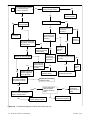
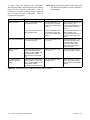
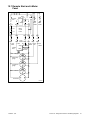
Refer to Figure 8-6 for troubleshooting information on the remote start panels.
Component
Ohmmeter Connections
Procedure
Results
Remote switch: yellow/red
wire terminal and black wire
terminal.
Place the ohmmeter on the
Continuity, the switch is
R x 1 scale.
functional. Open, replace
Press the rocker switch to the switch.
START position.
Remote switch: grey/black
wire terminal and black wire
terminal.
Place the ohmmeter on the
Continuity, the switch is
R x 1 scale.
functional.
Press the rocker switch to the
STOP position.
Generator set ON light,
gauge lights, DC voltmeter,
and hourmeter
Connect the red test lead to
P3-4 and black test lead to
P3-1.
Place the controller rocker
switch to the START position.
Stop the generator set when
the test is complete.
Generator set does not need
to be running, just cranking
for this test.
Note: If the hourmeter is not
illuminated, test it by
connecting it to a 12-volt
battery.
Note: The hourmeter is
polarity sensitive.
Water temperature gauge
Connect the red test lead to
P3-4 (socket side) and black
test lead to P3-2 (socket
side).
Start the generator set for the If 0.5--12-volts DC is present
test.
and the gauge does not
function after the J3 is
connected to controller,
replace the gauge.
Oil pressure gauge
Connect the red test lead to
P3-4 (socket side) and black
test lead to P3-3 (socket
side).
Start the generator set for the If 0.5--12-volts DC is present
test.
and the gauge does not
function after the J3 is
connected to the controller,
replace the gauge.
Remote start/stop switch
If 12-volts DC is present and
the component does not
function after the J3 is
connected to the controller
P3, replace the
component(s).
Note: Check continuity of gauge wiring and extension harness before replacing components.
Figure 8-6
44
Remote Start Panels Troubleshooting
Section 8 Component Troubleshooting
TP-6053 7/04