1
CHALLENGER,
NOMAD & MEDALIST
PISTOLS
FIELD
SERVICE
MANUAL
~BROWNINU
BROWNING FIELD SERVICE MANUAL
CHALLENGER, NOMAD & r""EDALIST PISTOLS
This manual is written to assist trained gunsmiths in the repair and servicing of Browning products. It should never be used by an
untrained person to repair any firearm. Read the entire manual carefully and pay special attention to the portions dealing with safety.
TABLE OF CONTENTS
SECTION
DESCRIPTION
PAGE
DESCRIPTION AND FUNCTIONAL
OPERATION
II
III
PARTS SCHEMATIC
INSPECTION AND DISASSEMBLY
INTO SUB-ASSEMBLIES
1.
2.
IV
DISASSEMBLY OF SUB-ASSEMBLIES
INTO COMPONENTS PARTS,
INSPECTION AND REASSEMBLY OF
SUB-ASSEMBLIES
1.
2.
3.
4.
5
6.
7.
8.
V
VI
Pre-Disassembly Inspection
Disassembly Into Sub-Assemblies
Disassembly of the Slide Assembly
Inspection of the Slide
Reassembly of the Slide Assembly
Disassembly of the Frame Assembly
Inspection of the Frame Assembly
Components
Reassembly of the Frame Assembly
Final Assembly and Adjustment
Final Inspection
2-3
4
4
4
4
4
4
4
5
6
6
7
7
TROUBLESHOOTING; POSSIBLE
CAUSES; SOLUTIONS
7
SPECIAL INSTRUCTIONS
8
BROWNING FIELD SERVICE
MANUAL
SECTION I
.IMPORTANT SAFETY WARNINGS
DESCRIPTION AND FUNCTIONAL
OPERATION
, Before performing any instructions given
throughout this manual, be certain to read
the NOTES and CAUTION notes given in
regard to those instructions. Generally, these
precautionary notes follow the related
instructions.
The Challenger is a blowback operated, .22
long rifle, semi-automatic pistol. The manual
Safety is a Sear blocking type that cannot
be placed in the "ON SAFE" position unless
the Hammer is cocked and the Slide is fully
forward.
Failure to obey a Safety Warning CAUTION
may result in injuries to you or to others.
When the Trigger is pulled to fire a
chambered (ound, it rotates ~bout the Trig
ger Pin and pulls the Disconnector forward.
The Disconnector Spring keeps upward
pressure on the' Disconnector so that a notch
in the Disconnector maintains engagement
with a protrusion on the Sear.
Failure to obey a NOTE regarding the repair
process may result in incorrect procedure
which could cause malfunctions and/ or
damage to the firearm.
'6mI'
WARNING
CAUTIONS:
T
1.
Be certain the firearm is unloaded
before proceeding with any service
work.
2. Appropriate safety glasses should be
worn by service personnel and
bystanders when removing or reinstall
ing any springs or spring-loaded
components.
3. As noted in the attached parts Jist on
Page 3 some of the Browning supplied
spare parts must be fitted by Browning
Service Department in Arnold, Missouri
or by qualified gunsmiths. No other
persons should attempt to fit these
specific parts.
4. If for any reason it becomes necessary
to load and discharge this firearm, it is
recommended that reference be made
to the Owners Manual for proper
loading, handling and safety procedures.
These manuals are supplied with each
new pistol and extra copies may be
obtained by contacting Browning, Route
# 1, Morgan, Utah, 84050.
5. Read all of the instructions, cautions
and notes on any step involving
assembly or disassembly before pro
ceeding with that step.
6. Section VI provides list of special tools
which may be required and special
instructions.
7.
CAUTION: Browning parts are made
exclusively for Browning guns and are
not recommended for use in other guns
even though models may be similar.
Inadequately fitted parts may be
dangerous. All repairs should be done
only by qualified gunsmiths.
Forward movement of the Disconnector
causes the Sear, to rotate and disengage the
Hammer notch. When the Sear disengages
the Hammer, the compressed Mainsprings
drive the Hammer forward to strike the Fir
ing Pin, compress the Firing Pin Spring, and
ignite the chambered round.
The pressure generated by the ignited round
blows the Slide back to extract and eject the
empty case, compress the Mainsprings,
recock the Hammer, and compress the
Recoil Spring.
As the Slide moves toward the rear, a ramp
in the Slide depresses the Disconnector
which disengages the notch from the protru
sion on the Sear. The notch in the Discon
nector cannot re-engage the protrusion on
the Sear until the Slide is completely for
ward in battery position and the Trigger is
released.
This constitutes the disconnecting feature of
the pistol. The Slide is moved forward to
chamber a live round from the Magazine
and back to battery position by force exerted
by the compressed Recoil Spring. When the
last round is fired and the Magazine is
empty, the Magazine Button pushes the Stop
Open Latch Assembly upward, against
pressure from the Stop Open Latch Spring,
to lock the Slide to the rear.
The Nomad operates identically to the
Challenger, except it does not contain a Stop
Open Latch Assembly or a Trigger Pull
Adjustment Screw. The Trigger Pull Adjust
ment affects Trigger pull in the Challenger
by varying Sear Spring tension. The Nomad
was produced with alloy as well as steel
Receivers.
The operation of the Medalist is identical to
the Challenger except that the Medalist can
be dry fired without the Firing Pin being
struck by the Hammer. This is accomplished
by a hook on the rear end of the Safety cat
ching a pin that protrudes from the side of
the Hammer. To operate in this mode, the
Safety is pushed forward in its elongated
Retaining Pin hole. The Hammer can then
be recocked by rotating the rear end of the
Safety downward.
.//
./
/P051
P051764!
U
yP051910
P051731/~
P051984~
~ P051805
.;:J
P051
frP051900
·05·~
P051908
891
P051894
.(; P051876
P051882is) /
/~/
0/
P051872
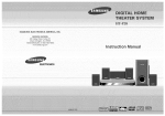
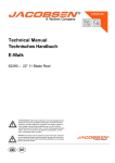
NOTE: These models are no longer manufactured and availability of parts is subjecf to inventory on hand.
Schematic is provided for parts identificafion only and should not be used as a guide to assemble guns.
2
SECTION II
PARTS SCHEMATIC 22 AUTO
22 Caliber Automatic Pistols Nomad/Challenger/Medalist
22 Long Rifle
NOTE: The Nomad, Challenger and Medalist pistols are no longer
serviced by the Browning' Arnold Service Center and replacement
parts are no longer available from that facility,
PART NO.
•
P051848
P051849
P051850
P051851
P051852
P051854
P051858
P051860
P051868
P051870
P051872
P051874
P051876
P051880
P051882
P051891
P051898
• P051892
P051893
P051895
P051894
P051896
P051897
P051900
P051908
P051910
P051921
P051924
PART NO. PART NAME
P051710
Slide, N-C-M
P051711
Barrel with Front Sight and Rear Sight Assembly
P051713
P051720
P051721
P051722
P051714
P051715
P051716
P051717
P051718
P051719
P051724
P051726
P051727
P051728
P051730
P051731
, P051732
P051736
P051738
P051740
" P051745
P051747
P051755
P051758
P051760
P051764
P051765
" P051788
P051790
P051791
P051794
P051793
P051799
P051805
P051820
P051838
P051830
P051825
P051826
P051827
P051828
P051829
P051831
P051833
P051835
Complete 4 112", N-C
_Barrel with Front Sight and Rear Sight Assembly
Complete ,6 3/4", N-C
Barrel with Front Sight and Rear Sight Assembly'
Complete with Ventilated Rib, M
Barrel Medalist International 5,9", M
Barrel Guide Pin, N-C-M
Counterweight Support - 2.4 1 oz" M
Counterweight Support Screw, M
Counterweight Support Bushing, M
Counterweight 252 oz_, M
Counterweight 1.79 oz" M
Counterweight ,94 oz., M
Counterweight Support and Weights
(Complete Set), M
Barrel Mounting Screw, N-C
Barrel Mounting Screw, M
Barrel Mounting Screw Washer, NC-M
Click Plate, N
Click Plate, C-M
Disconnector, N-C-M
Disconnector Spring, N-C-M
Recoil Spring Guide, N-C-M
Recoil Spring, N'C-M
Firing Pin, N-C-M
Fire Pin - For Dry Firing, M
Firing Pin Spring, N-C-M
Firing Pin Retaining Pin, N-C-M
Forearm, M
Forearm Screw, M
Forearm Screw Escutcheon, M
Sear, N-C-M
Sear Pin, N-C-M
Sear Spring, C-M
Sear Spring, N
Sear Spring Pin, C-M
Ejector, N-C-M
Ejector Deflection Pin, M
Extractor, N-C-M
Extractor Spring, N-C-M
Extractor Plunger, N-C-M
Sight Blade - Retaining Pin - Front, M
Sight Blade, Front New Type, N-C
Sight Retaining Pin, N-C
Sight Ramp - Front, NC
Magazine Body, N-C-M
Magazine Button, N-C-M
Magazine Follower, N-C-M
Magazine Spring, N-C-M
!'I- !'Iomad
C - Challenger
" Indicates part must be fitted by Browning
gunsmith
.''fOTE: unless
otherwis~
Strvic~
;\1 -
P051925
P051927
P051931
P051933
P051934
P051935
P051938
P051941
P051939
P051940
P051942
P051944
P051946
* P051970
" P051965
P051962
" P051977
* P051792
* P051980
, P051984
i\1edalist
!'I
Department or qualified
'1'
PART NAME
Grip - Wood - Medalist International Left Hand, M
Grip - Wood - Medalist International Right Hand, M
Grip - Wood - Right Hand Target, M
Grip - Wood - Left Hand Target, M
Stop Open Latch, C
Grip - Novadur - Plastic, N
Stop Open Latch Spring, C-M
Grip - Wood, C
Grip Screw, N
Grip Screw, C
Grip Screw, M
Grip Escutcheon - Threaded, N-C
Grip Escutcheon - Threaded, M
Grip Escutcheon - Unthreaded, N-C
Grip Escutcheon - Unthreaded, M
Hammer Link Pin, N-C-M
Hammer Link, N-C-M
Hammer, N-C-M
Hammer Pin, C-M
Hammer Pin, N
Main Spring Plunger. N-C-M
Main Spring - Inner, N-C-M
Main Spring - Outer, N-C-M
Magazine Latch, N-C-M
Magazine Latch Spring, N-C-M
Magazine Latch Pin, N-C-M
Sight Assembly Rear - Complete, N-C
Sight Assembly Complete with Rib and
Front Sight, M
Ventilated Rib Retaining Pin, M
Sight Base - Rear, N-C
Sight Base Mounting Screw - Rear, N-C
Sight Aperture - Rear, N-C
Sight Aperture - Rear. M
Sight Adjusting Screw - Rear - Windage, N-C
Sight Adjusting Bushing - Rear - Windage, M
Sight Adjusting Washer - Rear - Windage, M
Sight Adjusting Screw - Rear - Elevation, N-C
Sight Adjusting Screw - Rear - Elevation, M
Sight Tension Spring - Elevation, M
Sight Adjusting Screw Follower - Windage &
Elevation, M
Sight Adjusting Screw Follower Spring - Windage or
Elevation, M
Trigger - Blued, N
Trigger - Gold Plated - with Backlash Screw, C-M
Trigger Pin, N-C-M
Trigger Backlash Adjustment Screw, C-M
Trigger Pull Adjustment Screw C-M
Safety, N-C
Safety, M
!'Iomad
C - Challenyel
1'1 - ,i\1edaliot
Indicates part mU5t be tItted by Browning Service Department or qualified
gunsmith.
/.. .{OTE; unless otherwise indicated. port is interchangeable betwC'en gauges/calibers.
indicated. part is interchangeable between gouges/calibers.
3
SECTION III
Mounting Screw until the Barrel
Assembly can be removed from the
Frame Assembly by pushing the
Barrel to the rear and lifting upward.
INSPECTION AND DISASSEMBLY
INTO SUB-ASSEMBLIES
~
WARNING
"If'
1.
CAUTION: Make certain the
pistol is unloaded before any
inspection or disassembly opera~
tions are performed.
SECTION IV
DISASSEMBLY OF SUB-ASSEMBLIES
INTO COMPONENT PARTS, INSPEC
TION AND REASSEMBLY OF SUB
ASSEMBLIES
1.
DISASSEMBLY OF THE SLIDE
ASSEMBLY (Figure #3)
PRE-DISASSEMBLY INSPECTION
A. SAFETY
After the Magazine has been
removed and the pistol verified to
be unloaded,. cock the Hammer by
pulling the Slide to the rear and
place the Safety to the "ON SAFE"
position. Take the pistol in hand and
pull the Trigger firmly with the
index finger of that hand. The Trig~
ger should be pulled much harder
than normal but not sufficiently to
damage the Disconnector Assembly
or the Trigger. When pulling the
Trigger as outlined above, the Sear
must not disengage the Hammer,
and the Disconnector must not
disengage the Sear protrusion.
Release the Trigger and place the
Safety to the "OFF SAFE" position.
Moving the Safety to the "OFF
SAFE" position must not cause the
Sear to disengage the Hammer.
NOTE: When removing the
Nomad Barrel, the Slide must be
held to the rear by hand.
'&m'IF
WARNING
T
CAUTION: Do not let the Slide
Assembly of the Nomad fly off
the Receiver after removal of the
Barrel.
A. EXTRACTOR
Lay the Slide Assembly, left side
down, on a padded work surface which
After the Barrel Assembly has been
removed from the Frame, no further
disassembly of the Barrel Assembly
should be required.
will not scratch the polished Slide.
Using a sharp pointed scribe or
punch, not more than 1/16"
diameter, push the Extractor Plunger
to the rear. Work the point of the
B. SLIDE ASSEMBLY (Figure #2)
B. REGAIN
tool behind the Extractor and gently
Recoil Spdng Guide
With the Hammer cocked and the
Safety in the "OFF SAFE" position.
only partially disengage the Sear
from the Hammer notch by slightly
pulling the Trigger. Slowly release
the Trigger and observe the Trigger
moves to its original forward posi~
tion and the Sear has regained full
engagement back into the Hammer
notch.
pry the back of the Extractor upward
and out of the slot in the Slide.
~
WARNING
T
CAUTION: Use care not to let
the Extractor Plunger or Extrac~
tor Spring fly out of the Slide.
Remove the Extractor Spring and
plunger.
B. FIRING PIN
With a 1/16" punch remove the Fir~
C. TRIGGER PULL
Check the Trigger Pull for a
minimum let~off force of 3.5 Ibs.,
and a maximum of 4~5 Ibs~
,...
"tmm'W
WARNING
CAUTION: If the pistol fails any
of the inspection criteria above,
perform necessary repairs as out~
lined in this manual to correct
those discrepancies except for a
Trigger pull that may exceed 4.5
Ibs. by as much as one pound.
2. DISASSEMBLY INTO SUB
ASSEMBLIES
A. BARREL ASSEMBLY (Figure # 1)
ing Pin Retaining Pin from top to
FIGURE #2
On pistols other than the Nomad,
grasp the Frame Assembly in one
hand and the Slide Assembly in the
other. Pull the Slide Assembly
slightly to the rear to disengage the
Stop Open Latch and slowly let the
Slide Assembly move forward and
off the Frame Assembly.
,...
~
WARNING
CAUTION: Use care not to
allow the Recoil Spring or Recoil
Spring Guide to fly out of the
Frame Assembly.
Remove the Recoil Spring and Recoil
Spring Guide~
bottom.
,...
"Elm'IP'
WARNING
CAUTION: Do not let the
Fir~
ing Pin and spring fly out of the
Slide upon removal of the punch~
2. INSPECTION OF THE SLIDE
Using a No. 31 reamer or drill bit.
remove any burrs or accumulated
debris from the Extractor Spring hole.
3. REASSEMBLY OF THE SLIDE
ASSEMBLY
A. FIRING PIN
Lay the Slide inverted on a padded
Pull the Slide back until it is locked
work surface.
in the rear position by the Stop
Open Latch and remove the Maga~
zine. With a blade screwdriver
ground to fit. loosen the Barrel
Insert the Firing Pin Spring and Fir~
ing Pin in the Firing Pin hole. Be
certain the flat side of the Firing Pin
4
notch is positioned toward the Firing
upward as shown in Figure # 13 and
Remove the Sear Spring Pin with a
Pin Retaining Pin hole.
pulling directly to the rear.
3/32" punch.
Push the Firing Pin forward until the
Lift out the Stop Open Latch after
Disconnect the Sear Spring from the
notch is centered under the Firing
the Grips are removed.
point of the Trigger Pull Adjusting
Place the Safety in the "OFF SAFE"
Screw by pushing downward on the
rear end of the Spring,
Pin Retaining Pin hole.
position. Pull the Trigger and slowly
NOTE: Some early pistols were
manufactured using solid Firing
let the Hammer move forward until
NOTE: Make sure the Trigger
Pin Retaining Pins. It is recom
it stops on the Frame.
Pull Adjusting Screw is turned
mended a ] /8" diameter by
Observe how the Disconnector and
into the Frame sufficiently so as
approximately 11 / 32" long Roll
Disconnector Spring ~re positioned,
not to bind the Sear Spring
Pin be used for reinstalling the
and then lift them out of the Frame.
against the rear of the Frame.
Firing Pin.
When the Firing Pin notch is pro
perly aligned, carefulfy install the
Firing Pin Retaining Pin.
NOTE: The Nomad does not
B. TRIGGER, CLICK PLATE,
SEAR, SPRING AND PINS
(Figure # 5)
contain a Trigger Pull Adjusting
Screw.
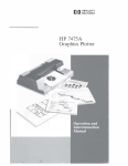
D. HAMMER ASSEMBLY,
SAFETY ASSEMBLY, MAIN
SPRINGS AND MAINSPRING
PLUNGER (Figure # 7)
Center punch the Slide at two spots
around the periphery of the Firing
Pin Retaining Pin hole to keep the
Roll Pin from working loose and
dropping out of the Slide.
B. EXTRACTOR
Hammer Assembly
Mainspring Plunger
\
To reassemble the Extractor, lay the
Mainspring
Slide. left side down, on a padded
surface. Insert the Extractor Spring
and plunger into the Spring hole
being certain the flat side of the
Extractor Spring Plunger is posi
tioned toward the inside of the
FIGURE #5
Using a 3/32" punch. remove the
Slide. Insert the Extractor by
Trigger Pin and Trigger.
pushing the Extractor Spring
Using a 1/16" punch and by mov
Plunger to the rear until the Extrac
ing from left to right, disengage the
tor snaps into position.
4.
FIGURE #7
DISASSEMBLY OF THE FRAME
ASSEMBLY
Sear Pin from the Safety Click Plate,
Place the Frame inverted on a
and then lift out the Safety Click Plate.
padded surface and remove the
Hammer Pin from the right side of
NOTE: Reference to the left or
padded surface and remove the Sear
the Frame to the left using a 3/32"
right side of the Frame relates to
those sides as observed when
Pin from the left side of the Frame
punch.
to the right with a 3/32" punch.
shooting the pistol.
Place the Frame inverted on a
1I:1olmIP'
WARNING
A. GRIp, STOP OPEN LATCH,
DISCONNECTOR AND DIS
CONNECTOR SPRING (Figure #4)
T
To prevent damage to the Grip, cock
the Hammer and place the Safety in
the "ON SAFE
CAUTION: If the Sear is not
NOTE: The Stop Open Latch
Spring w;11 be contained on the
ejected from the Frame Assem·
Hammer Pin.
bly when the punch is withdrawn,
keep the Frame on the padded
Keeping the Frame inverted on the
padded surface, slowly. withdraw the
surface and push the Sear out by
punch and observe the Hammer
inserting the punch through the
large side hole.
Assembly, Mainsprings and plunger
fly out of the Frame and impact on
position.
C. SEAR SPRING AND SEAR
SPRING PIN (Figure # 6)
the padded surface.
1I:1olmIP'
WARNING
T
CAUTION: If the plunger hangs
up on the Safety Assembly, and
the Mainsprings are still com
pressed, work the plunger loose
by inserting the punch through
the large side hole while keeping
the Frame inverted.
Remove the Safety Assembly, Ham
mer Assembly, Outer Mainspring,
Inner Mainspring and Mainspring
Plunger.
E. MAGAZINE LATCH, SPRING &
PIN (Figure #8)
FIGURE 14
Remove the Grip Screw and Grips
by rotating the rear end of the Grips
Using a 3/32" punch, remove the
FIGURE #6
5
Magazine Latch Pin, Magazine Latch
onto the Trigger Pull Adjusting
and Magazine Latch Spring,
Screw as shown in Figure #9.
With the Hammer Link positioned
midway in the Hammer, install the
Hammer Assembly in the Frame to
Back the Trigger Adjusting Screw
the right of the Safety Assembly.
Align the holes in the Hammer
Assembly and the Safety Assembly
with the holes in the Frame using a
3/32" punch from right to left.
Install the Hammer Pin, along with
the Stop Open Latch Spring, from
left to right.
out until it is approximately flush
with the rear surface of the Frame.
B. MAINSPRINGS AJ"'lD
MAINSPRING PLUNGER
Position the Inner and Outer
"'\ainsprings on the M'ainspring
Plunger and place in the Mainspring
Verify the Hammer Pin is through
both sides of the Frame. Align the
end of the Hammer Link with the
hole. Grip a long 3/32" punch in a
vise and' compress the Mainspring
until the top of the plunger is below
..
plunger in this position and install a
"'6lm1f
WARNING
5.
recess in the "'\ainspring Plunger.
Press downward on the Hammer
with one thumb and slowly withdraw
the 3/32" punch.
the 3/32" cross hole, Hold the
3/32" p\lnch across the top of the
CAUTION: Use care not to let
plunger and through both sides of
the spring·loaded components fly
After the 3/32" punch is withdrawn,
verify the Hammer Link is seated in
the center of the Mainspring
Plunger.
the Frame as shown in Figure # 10.
out of the Frame.
INSPECTION OF THE FRAME
ASSEMBLY COMPONENTS
~
A. SEAR
WARNING
T
Inspect the Sear and replace if signs
of alteration exist.
B. HAMMER
Inspect the Hammer Sear notch and
replace if signs of excessive wear or
6. REASSEMBLY OF THE FRAME
ASSEMBLY, MAGAZINE LATCH
(Figure #8)
"'\agazine Latch, Magazine Latch Spring
and Magazine Latch Pin.
A. SEAR SPRING AND SEAR
SPRING PIN (Figure #6)
Install the Sear Spring and Sear
Spring Pin with orientation of the
spring as shown in Figure # 6,
Turn the Trigger Pull Adjusting
Screw fully into the Frame,
'DimF
WARNING
'"
CAUTION: Use extreme care
not to let the plunger and com
pressed Mainspring fly out and
cause serious injury.
toms on the Frame.
C. SAFETY ASSEMBLY, HAM
MER ASSEMBLY, HAMMER
PIN AND STOP OPEN LATCH
SPRING
NOTE: If the assembly is incor·
rect, remove the Hammer as
previously outlined and
reassemble.
Position the Safety Assembly for
installation through the large hole in
the 3/32" punch, verify the
Hammer Link will seat in the
Mainspring Plunger and the
Hammer Pin extends through
both sides of the Frame.
NOTE: After withdrawing the
3/32" punch, the Hammer may
be retained in the depressed
position by the ends of the Sear
Spring engaging the Sear notch
of the Hammer. If so, depress the
Hammer slightly, depress the
ends of the Sear Spring with a
blade screwdriver and slowly let
the Hammer forward until it bot·
alteration exist.
Using a 3/32" punch, install the
CAUTION: Before withdrawing
D. SEAR AND SEAR PIN
the left side of the Frame.
(Figure # 5)
NOTE: If the Stop Open Latch
Position the Sear between the Ham
mer and the long ends of the Sear
Spring and align the hole in the
Sear with the holes in the Frame.
Install the Sear Pin from right to left
with the small end of the Sear Pin
toward the left. The Sear Pin will be
Spring was removed from the
Hammer Pin, refer to Figure # 11
for proper orientation.
in proper position when its large
end is flush with the surface of the
Frame Disconnector Cavity.
"'lII!Llm1f'
WARNING
T
FIGURE 119
Hold the Frame in one hand and a
CAUTION: Verify the long ends
of the Sear Spring are centrally
located between the two projec·
tions at the bottom of the Sear.
E. SAFETY CLICK PLATE
blade screwdriver in the other. Pry
upwards on the rear end of the Sear
(Figure #5)
Position the Safety Assembly to the
Spring until it is spread and forced
6
"OFF SAFE" position and depress
the Hammer to the cocked position.
Slide fully to the rear and lock it
there by moving the Stop Open
Latch upward.
Install the Disconnector Spring as
shown in Figure # 12.
Position the Safety Click Plate bet·
ween the Frame and the Safety
Assembly. Align the small hole with
the Sear Pin and the large hole with
the Hammer Pin.
~
WARNING
T
Hold the Safety Click Plate in this
position and slowly move the Safety
Assembly to the "ON SAFE" posi·
tion. Be certain that holes in the
Safety Click Plate hold alignment
with the pins.
With the Slide held to the rear by
the Stop Open Latch, position the
Barrel Assembly on the Frame
Assembly and install the Barrel
Mounting Screw and washer if
previously removed.
I. GRIPS
Make sure the Safety is in the "ON
NOTE: Do not overtighten the
SAFE" position and install the Grips
Barrel Mounting Screw.
by first sliding them onto the Frame
NOTE: After the Safety Click
Depress the Stop Open L.atch and
allow the Slide to move forward
against the Breech Face of the Bar·
reI. With the Slide in the forward
position, move the Safety Assembly
to the "ON SAFE" position.
as shown in Figure # 13.
Plate is in pOSition, verify the
large end of the Sear Pin is still
flush with the surface of the
Frame Disconnectar Cavity.
F. STOP OPEN LATCH
ASSEMBLY (Figure #4)
Install the Magazine.
Position the Stop Open Latch
Assembly on the Frame with the tip
of the Stop Open Latch Spring posi·
tioned in the small cutout on the
Stop Open Latch.
8.
FINAL INSPECTION
Refer to Section III, Para. 1 and perform
the inspection sequences "PRE·
DISASSEMBLY INSPECTION" in their
entirety.
G. TRIGGER AND TRIGGER PIN
NOTE: Use the Trigger Pull
Adjusting Screw to adjust the Trig·
ger pull to 3.5 to 4.5 Ibs.
FlG(JRE # 13
Install the Trigger and Trigger Pin
from right to left. After installation
be certain the Trigger pivots freely
on the Trigger Pin without binding.
Next. rotate the Grips into position
and install the Grip Screw.
With the Hammer cocked, press the
Disconnector downward, release and
H. DISCONNECTOR AND
DISCONNECTOR SPRING
verify the Disconnector Spring will
move the notch on the Disconnector
(Figure #4)
into proper engagement with the
Position the Disconnector Assembly
on the Frame with the Disconnector
Pivot Pin inserted into the upper
hole of the Trigger.
protrusion on the Sear.
With the Hammer still in the cocked
position. move the rear end of the
Disconnector upward to engage the
protrusion on the Sear.
7.
FINAL ASSEMBLY
A. SLIDE AND FRAME
ASSEMBLIES
SECTION V
TROUBLESHOOTING / POSSIBLE
CAUSES/ SOLUTIONS
~
WARNING
T
1.
With the Magazine removed from
CAUTION: Make certain the
pistol is unloaded before per·
forming any troubleshooting.
FAILS TO EXTRACT
A. Dirty or burred Chamber -
Ream
lightly using a .22 L.R. Chamber
Finisher Reamer.
the Frame, place the Hammer in the
cocked position and the Safety in
Ascertain the Disconnector slips
freely over the protrusion on the
Sear and clearance of approximately
.003" exists between the Sear and
Disconnector.
been locked into the rear posi·
tion, use care not to bump the
Stop Open Latch which would
allow the Slide and Recoil Spring
to fly off the Frame.
B. BARREL ASSEMBLY AND
MAGAZINE
The Safety Click Plate should now be
flush with the Frame'. Additionally,
the round indent on the Safety
Assembly should be positioned in the
detent on the Safety Click Plate and
the holes in the Safety Click Plate
should be aligned with the pins.
(Figure # 5)
CAUTION: After the Slide has
the "OFF SAFE" position.
B. Weak Extractor Spring.
Position the Slide into the grooves
of the Frame. Place the Recoil
C. Dull or improperly fit Extractor.
Spring into the slotted hole in the
Slide.
D. Burrs on Extractor Spring Foliower.
Adjusting Screw, located in the
top of the Trigger, may be used
to adjust this clearance. If
Position the Recoil Spring Plunger
E. Loose Barrel Assembly
adjusted too closely, the Discon·
nectar may not engage the Sear
reliably and malfunctions will
result.
rear of the Frame. Slowly withdraw
NOTE: The Trigger Backlash
into the spring and the other end of
F. Burred or dirty Extractor Spring
the plunger on the projection at the
the Slide and feed the Recoil Spring
hole.
2.
FAILS TO EJECT
and Recoil Spring Guide into the
slotted hole in the Slide. Pull the
A. Missing Extractor.
3. WILL NOT FEED OR JAMS
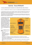
2.
SPECIAL TOOLS
A. Improperly adjusted Magazine Lips.
B.
Loose Barrel Assembly.
C.
Breech Face peened over by too
long Firing Pin - Usually happens
with a Broken Firing Pin (rare).
D. Weak Recoil Spring.
4. FAILS TO FIRE (Hammer Falls)
A. Loose Barrel Assembly.
5. WILL NOT FIRE (Hammer Will Not
Fall)
A. Disconnector Spring improperly
positioned.
B.
Disconnector binding and not
engaging the Sear.
FIGURE 1114
A. Pointed scribe.
B.
Long liS" punch.
C. Slender needlenose pliers.
C. Broken Disconnector Spring.
6. POOR GROUPING
A. Loose Barrel Mounting Screw.
B.
Loose Sights.
C. Barrel needs recrowning.
SECTION VI
SPECIAL INSTRUCTIONS
1.
RECOMMENDED POINTS OF
LUBRICATION DURING
REASSEMBLY
Lightly oil the following areas with
Browning Gun Oil. Always use oil
sparingly.
A. Extractor Spring hole.
B.
Slide Rails.
C.
Hammer and Sear Pins.
D.
Rear end of Disconnector.
E. Exterior surface.
8