1
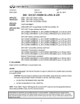
Classification :
Reference:
Dat e:
BT13-016
ITB13-058
December 19, 2013
2009-2013 G37 CONVERTIBLE;
SQUEAK / RATTLE / BUZZ NOISE FROM ROOF AND TRUNK AREAS
This bulletin supersedes ITB10-071, ITB11-035, ITB12-003, and ITB13-032.
APPLIED VEHICLE: 2009 - 2013 G37 Convertible (HV36)
IF YOU CONFIRM:
There is a squeak, rattle, “buzz”, or rubbing type noise coming from the retractable hard top or trunk areas while
driving.
•
See page 4 and 5 for specific locations and types of noises.
ACTION:
Refer to the Repair Overview on page 4 and 5.
IMPORTANT: The purpose of ACTION (above) is to give you a quick idea of the work you will be performing.
You MUST closely follow the entire Repair Overview as it contains information that is essential to successfully
completing this repair.
Infiniti Bulletins are intended for use by qualified technicians, not 'do-it-yourselfers'. Qualified technicians are properly trained
individuals who have the equipment, tools, safety instruction, and know-how to do a job properly and safely. NOTE: If you believe
that a described condition may apply to a particular vehicle, DO NOT assume that it does. See your Infiniti dealer to determine if this
applies to your vehicle.
1/35
PARTS INFORMATION
(a)
(b)
(c)
(d)
(e)
(f)
(g)
DESCRIPTION
PART NUMBER
QTY
Lock Assy-Folding Roof
97096-JJ50B
1
Repair Procedure A
Tape
J-50397-15
(a) (b)
PAD (felt cloth and tape kit)
97085-JJ52D
1 (c)
Repair Procedure C
O-RING
970D3-JJ50A
2 (d)
Pin - Roof Center, LH
73159-JJ50C
1
Repair Procedure D
Pin - Roof Center, RH
73158-JJ50C
1
®
Repair Procedure E
DuPont Krytox Lubricant – GPL-105
82306-5Z000
(e)
PAD (felt cloth and tape kit)
97085-JJ52D
1 (f)
Repair Procedure F
MALE ASSY – DOVETAIL
844A7-JJ50B
(g)
Available in Squeak & Rattle Kit #J-50397.
One part will repair more than one vehicle.
If needed. Only the 1 mm sheet is used. This part will repair more than one vehicle.
If needed.
Order this product from your PDC. One container per vehicle.
There are three sheets of felt cloth in three different thicknesses. Use the chart on page 33 to determine the
location of each thickness of felt cloth. All pieces will need to be cut to size.
Up to two pieces, as needed.
2/35
ITB13-058
CLAIMS INFORMATION
For procedures A – E be sure to claim on the same repair line
Repair Procedure A:
Submit a Primary Part (PP) type line claim using the following claims coding:
DESCRIPTION
PFP
OP CODE
SYM
DIAG
Replace Latch
73159-JJ50B
SA32AA
ZL
46
(1) Reference the current Infiniti Warranty Flat Rate Manual and use the indicated FRT.
FRT
(1)
Repair Procedure B:
Submit a Primary Part (PP) type line claim using the following claims coding:
DESCRIPTION
PFP
OP CODE
SYM
Apply Grease
73159-JJ50B
SX10AA
ZL
DIAG
46
FRT
0.3
DIAG
FRT
46
0.3
DIAG
FRT
46
0.4
DIAG
46
FRT
0.3
Repair Procedure C:
Submit a Primary Part (PP) type line claim using the following claims coding:
DESCRIPTION
PFP
OP CODE
SYM
Perform Ball Joint and Socket
Align Adjustment
73159-JJ50B
SX06AA
ZL
Repair Procedure D:
Submit a Primary Part (PP) type line claim using the following claims coding:
DESCRIPTION
PFP
OP CODE
SYM
Remove Shims
73159-JJ50B
SX11AA
ZL
Repair Procedure E:
Submit a Primary Part (PP) type line claim using the following claims coding:
DESCRIPTION
PFP
OP CODE
SYM
Clean All Weather Strips
73159-JJ50B
SX07AA
ZL
Only Claim Procedure F on a separate repair line
Repair Procedure F
Submit a Primary Part (PP) type line claim using the following claims coding:
DESCRIPTION
PFP
OP CODE
SYM
DIA
FRT
Repair Rear Roof
97160-JJ50A
SX08AA
ZL
46
5.6
3/35
ITB13-058
SERVICE PROCEDURE
Repair Overview
Use the following pictures on the next two pages to determine which repairs to perform.
# 1) Pop type noise; perform Repair Procedure A starting on page 6.
# 2) Creak type noise; perform Repair Procedure A starting on page 6.
# 3) Rattle type noise; perform Repair Procedure B starting on page 8.
# 4) Ticking type noise; perform Repair Procedure C starting on page 9.
# 5) Rear roof panel movement; perform Repair Procedure D starting on page 11.
•
A ticking and/or rattle type noise may also be heard along with rear roof panel movement.
For # 6 and # 7, go to the next page.
NOTES:
Perform all repairs in a clean work environment. Make sure your hands/gloves are clean.
Use fender covers when leaning over the sides of the vehicle.
Use protective covering as needed if and when positioned inside the vehicle.
Rear roof panel
1
1
(with rear window glass)
3
2
4
3
4
5
Front roof panel
Center roof panel
Figure 1
4/35
ITB13-058
# 6) Rubbing/creak type noise; perform Repair Procedure E starting on page 13.
6
Figure 2
# 7) Any squeak, rattle, or “buzz” type noise is heard in the shaded area below; perform Repair Procedure F
(starting on page 15) when:
# 1-6 do not apply
OR
One or more of # 1-6 have been performed, the remainder of # 1-6 do not apply, and other noises are still
heard in the shaded area below.
7
Figure 3
5/35
ITB13-058
Repair Procedure A
Perform this repair for one or both of the following noises:
•
A “pop” type noise in heard in the sun visor area(s) when the vehicle is turning and/or the body flexes.
•
A “creak” type noise is heard in the center of the front roof garnish when the roof is warm, and driving
over bumps.
Front roof garnish
Figure 1a
1. Replace the roof lock assembly (see PARTS INFORMATION on page 2).
•
Refer to the K BODY EXTERIOR, DOORS, ROOF & VEHICLE SECURITY > RF Roof section of the
Electronic Service Manual (ESM).
2. Before installing, add tape to the roof latch motor where noted on the next page.
•
Inspect the condition of the felt tape on the front roof garnish’s clips.
6/35
ITB13-058
Tape – cut three 20 x 25 mm pieces
Poke a hole through each piece of tape
Roof lock assembly
Figure 2a
Make sure 10 x 50 x 1 mm pieces of felt
tape are in place and not damaged
Figure 3a
Figure 4a: Front roof garnish
7/35
ITB13-058
Repair Procedure B
Perform this repair when a rattle type noise is heard on either side between the front and center roof panels
when driving over large bumps or potholes.
1. Partly open the retractable hard top (or roof) as
shown in Figure 1b.
CAUTION: When left in a partially open position,
the roof could slowly drop which may cause roof
damage.
Figure 1b
Front roof
panel
2. Locate the slider bars between the front and
center roof panels on both sides of the roof
(see Figure 2b).
Slider bar
3. Apply a thin coat of heavy bearing grease or
equivalent with a cotton swab or small brush
on both slider bars where shown in Figure 3b
and 4b.
CAUTION: Be careful not to apply an excess
amount of grease. It may eventually get on the
headlining, causing a stain.
Figure 2b
Apply grease
on slider bar
inner edge
ONLY
Apply grease
on upper edge
ONLY
Figure 3b
Figure 4b
8/35
ITB13-058
Repair Procedure C
Perform this repair when a ticking type noise is heard around the upper corners of the rear roof panel when
driving.
NOTE: The rear roof panel includes the rear window glass.
Rear roof panel
1. Partly open the roof as shown in Figure 1c.
CAUTION: When left in a partially open position,
the roof could slowly drop which may cause roof
damage.
Center roof panel
Figure 1c
2. Check both O-rings for impressions.
•
There is one (1) O-ring at each rear corner
of the center roof panel, mounted on center
roof panel pins as shown in Figure 2c.
Center roof panel pin
O-ring
Figure 2c
9/35
ITB13-058
3. If impressions are found on either O-ring (see example in Figure 3c):
a. Replace both roof panel pins (or pins) if they have not been previously replaced with the ones listed in
PARTS INFORMATION (see Procedure D for pin replacement).
OR
b. If the pins were previously replaced with the ones listed in PARTS INFORMATION, replace the O-rings
only.
NOTE: Pins come with O-rings, and the O-rings are available separately (see PARTS INFORMATION).
Impressions on O-ring
Roof panel pin
Figure 3c
Figure 4c
3. Next, loosen the Torx screws (size T-30) for both rear roof panel retainers. See Figure 5c.
•
•
The retainers are located at both front corners of the rear roof panel.
Loosen the retainers enough so they move around easily by hand, but not on their own.
Retainer
Rear roof panel
Figure 5c
4. Fully close the roof.
• This will allow the retainers to align with the pins.
5. Open the roof, and then tighten the retainer’s Torx screws.
•
Torx screws torque: 9.5 N•m (0.97 kg-m, 84 in lb)
10/35
ITB13-058
Repair Procedure D
Perform this repair when the rear roof panel moves side-to-side when driving over bumps.
•
A ticking and/or rattle type noise may be heard during this issue.
Rear roof panel
1. Partly open the roof as shown in Figure 1d.
CAUTION: When left in a partially open position,
the roof could slowly drop which may cause roof
damage.
Figure 1d
2. Loosen the two Torx screws of both roller hooks,
and then remove the shims behind them.
•
Rear roof panel
There are two roller hooks, one on each side
of the rear roof panel.
•
Keep the roller hooks in their original
positions as they were before loosening
when tightening their Torx screws.
•
If needed, mark the roller hooks’ positions
prior to loosening with a suitable marker that
can be cleaned off after this repair.
Roller hook
CAUTION: If the roller hooks do not keep
their original positions, they may not latch
properly which may cause damage.
Figure 2d
Shim
3. After removing the shims, tighten the roller hooks’
Torx screws.
•
Torx screws torque: 8.5-10.5 N•m (0.871.07 kg-m, 75.2- 92.9 in lb)
•
Clean off any markings.
CAUTION: If the roller hooks are not secured in
their original positions, they may not latch properly
which may cause damage.
Figure 3d
11/35
ITB13-058
4. Replace both roof panel pins (or pins).
•
Both pins can be accessed by reaching inside the headlining where shown in Figure 4d.
•
Figure 5d shows the headlining removed for pin location only. The headlining does not
need to be removed to access the pins.
Access pins from here…
…and here
Figure 4d
Figure 5d
Figure 6d
12/35
ITB13-058
Repair Procedure E
Perform this repair when a rubbing or creaking type noise is heard from any section of any roof seal while
driving.
1. Partly open the roof as shown in Figure 1e.
CAUTION: When left in a partially open position,
the roof could slowly drop which may cause roof
damage.
Figure 1e
2. Using a damp cloth, clean the contact surfaces of
all roof related weatherstrips (see Figure 2e).
Figure 2e
•
Also clean the area of the seal (where circled
in Figure 2e and 3e) on both sides of the
vehicle.
Figure 3e
13/35
ITB13-058
3. Using your finger, apply a thin coat of DuPont
Krytox® Lubricant on all cleaned weatherstrip
contact surfaces.
•
DuPont Krytox® Lubricant is available from
your local PDC. See PARTS INFORMATION
on page 2.
•
Make sure to apply lubricant on both
surfaces of seals with two (2) contact
surfaces. See Figure 4e for example.
•
For cleanliness, it is recommended to
use latex or similar type gloves.
Figure 4e
Lubricant
14/35
ITB13-058
Repair Procedure F
Perform this repair procedure when:
• Any squeak, rattle, or “buzz” type noise is heard in the roof area
AND
• Repair Procedures A-E do not apply
OR
• One or more of Repair Procedures A-E have been performed, the remainder of
Repair Procedures A-E do not apply, and other noises are still heard in the roof area.
For tape and felt identification and location, refer to page 32-34. For parts needed, see PARTS INFORMATION
on page 2.
1. Remove the rear roof lower
garnish with a suitable pry tool.
Rear roof lower garnish
Parcel shelf finisher board
Rear seatback
Figure 1f
2. Cut two 10 mm x 100 mm pieces of felt cloth from the 1 mm sheet, and then install where shown in Figure 2f.
3. Break off the locator pin with suitable pliers (see Figure 2f).
Felt cloth
Felt cloth
Locator pin
Figure 2f
4. Cut six 10 x 50 mm pieces from the 1 mm sheet, and apply to the clips as shown in Figure 3f, and
where circled in Figure 2f.
Figure 3f
15/35
ITB13-058
5. Next, position the roof as shown in Figure 4f.
CAUTION: When left in a partially open position, the roof could slowly drop which may cause roof damage.
6. Remove the rear roof upper garnish with a suitable plastic pry tool.
Rear roof upper garnish
Figure 4f
7. Break off flush both locator pins. See Figure 6f, and arrows in Figure 5f.
Back side
Figure 5f
8. Remove any existing felt cloth from all clips.
9. Cut four 50 mm pieces from the tape roll, and then apply on the clips. See Figure 7f, and where circled
in Figure 5f.
Break off
Apply felt cloth
Figure 6f
Figure 7f
16/35
ITB13-058
10. Next, remove the front roof garnish with a suitable pry tool.
Front roof garnish
Figure 8f
11. Apply felt cloth (from the tape roll) along the white dotted line in Figure 9f.
Front roof garnish, back side
Figure 9f
•
Figure 10f shows side view (cutaway) of felt cloth position.
Felt cloth
Front roof garnish base
Trim
Figure 10f
17/35
ITB13-058
12. If felt cloth is already applied as shown in Figure 11f, skip to Step 15.
•
If not, go to the next step.
Figure 11f
Figure 12f
13. Remove any felt cloth found at the sides of the clips (see Figure 13f).
Remove
Figure 13f
14. Cut seven 10 mm x 50 mm pieces from the 1 mm sheet, and apply to the clips as shown in Figure 11f and
12f.
18/35
ITB13-058
15. If felt cloth is already applied as shown in Figure 14f, skip to Step 16.
•
If not, go to the next step.
15a. Apply felt cloth to both plates where shown in Figure 14f.
Figure 13f
•
•
5
Cut two 50 mm long pieces of felt cloth from the tape roll and wrap one at location 1 on
each plate (see Figure 14f).
Cut two 10 mm x 20 mm pieces from the 3 mm felt cloth
sheet, and then apply one at
location 2 on each plate (see Figure 14f).
1
2
Figure 14f
19/35
ITB13-058
16. Next, drop down the headlining and lay out on the rear back seat to access the rear rib (see Figure 15f).
•
Refer to the K BODY EXTERIOR, DOORS, ROOF & VEHICLE SECURITY > RF ROOF section of
the ESM as needed.
•
Do not entirely remove the headlining. Leave the tether cords fastened.
NOTE: The rear rib comes attached to the headlining. It is shown
separate in Figure 16f for easier viewing.
Rear rib
Headlining dropped
Figure 15f
1
Rear rib
Tape
f
Headlining
Rear rib
Four pieces of
20 mm x 300 mm x 2 mm felt cloth
Center position
Figure 16f
17. Remove any existing pieces of felt cloth where outlined in blue in Figure 16f.
18. Cut four 20 mm x 300 mm pieces (approximate in length) from the 2 mm sheet.
19. Apply the cut pieces across the length of the rear rib where outlined in blue in Figure 16f.
•
Start and finish the application from edge to edge as shown in Figure 17f.
20/35
ITB13-058
20. Cut five 30 mm x 35 mm pieces from the 1 mm sheet.
21. Fold in half the longer length of each piece, and then cut a hole at the middle of the fold: 3 mm deep
by 5 mm wide (see Figure 18f).
3 mm
5 mm
Figure 18f
22. Apply these pieces where shown in Figure 19f and 20f.
Figure 19f
Figure 20f
21/35
ITB13-058
23. Remove any existing pieces of clear tape from the edge of the rear rib (under blue outline).
See Figure 21f.
•
It is ok to leave the adhesive residue from any removed tape on the rib.
24. Cut pieces from the tape roll, and then apply on the edge where outlined in blue and black
(see Figure 21f and 22f).
•
For easier application, cut the felt cloth in sections.
Figure 21f
Figure 22f (side view)
22/35
ITB13-058
25. Remove any existing pieces of felt cloth from on and around the clips.
Locator pin
Clips
Figure 23f
26. Cut four 10 mm x 50 mm pieces from the 1 mm sheet, and then apply one to each clip as shown in
Figure 24f, and where pointed out in Figure 23f.
Apply felt cloth here
Clip
Figure 24f
27. Break off the locator pin flush, and then apply a piece of felt cloth tape where broken off (see Figure 25f).
• Felt cloth length (cut from the tape roll): 50 mm long
Break off pin
Felt cloth
Figure 25f
23/35
ITB13-058
28. Inspect both center roof panel pins for felt cloth (see Figure 27f).
•
•
If felt cloth is found, skip to step 30.
If none, go to the next step.
29. Cut two 20 mm x 80 mm pieces from the 2 mm sheet, and then apply one on each center roof panel pin as
shown in Figure 27f, and where pointed out in Figure 26f.
NOTE: The center roof panel pin in Figure 27f is shown as removed for easier viewing. These pins do not
need to be removed to apply the felt cloth.
Figure 26f
Felt cloth
Figure 27f
24/35
ITB13-058
30. Cut two 20 mm x 20 mm pieces from the 2 mm sheet, and then apply one piece on each
side of the roof as shown in Figure 29f, and where pointed out in Figure 28f.
Rear roof panel
Center roof panel
Figure 28f
Felt cloth
Figure 29f
25/35
ITB13-058
31. Cut two 50 mm pieces from the tape role, and then wrap one piece on each of the two rear window
defogger connectors (see Figure 30f).
Felt cloth
Rear window defogger connector
Figure 30f
32. Apply “super glue” or equivalent adhesive to ALL tether cord clips where shown in Figure 31f.
Figure 31f
33. Reinstall the headlining.
•
Refer to the K BODY EXTERIOR, DOORS, ROOF & VEHICLE SECURITY > RF ROOF
section of the ESM as needed.
Continue to the next page.
26/35
ITB13-058
34. Next, fully close the roof.
35. Proceed to open the roof until the trunk lid is in the position shown in Figure 32f.
36. If felt cloth is found under the flipper doors where pointed out in Figure 32f, skip to Step 38.
• If none found, go to the next step.
Flipper door
Trunk lid
Figure 32f
37. Cut six 20 mm x 30 mm pieces from the 3 mm sheet (three for each flipper door), and then apply under
both flipper doors as shown in Figure 33f and 34f.
Figure 33f
One piece
Figure 34f
27/35
Two pieces
ITB13-058
38. Next, adjust the side wedges of the vehicle’s trunk as shown in Figure 36f, and where
pointed out in Figure 35f.
•
There are two wedges, one on each side.
•
T40 Torx bolts torque: 23.5 - 27.5 N•m (2.4 - 2.8 kg-m, 17.3 - 20.3 ft lbs)
Figure 35f
: New position
Figure 36f
28/35
ITB13-058
39. Next, fully close the roof, and then open the trunk lid as if accessing the trunk area normally.
40. Adjust the trunk lid bumpers as follows:
Bumpers
a
Trunk lid
Figure 37f
Rubber
b
“Flower”
d
a
Figure 38f
Figure 39f
Figure 40f
a. Remove both bumpers (see Figure 37f).
b. Turn to extend the rubbers of both bumpers all the way out (see 38f).
c. Turn the “flowers” until they bottom out under the rubbers (see Figure 39f).
d. Reinstall both bumpers, and then carefully slowly close and latch the trunk lid.
e. Open the trunk lid, and then turn both “flowers” clockwise until they bottom out (see Figure 40f).
•
Perform this last step with the bumpers still installed.
•
Make sure the rubbers do not move during this step.
29/35
ITB13-058
41. Next, close the trunk lid, open the roof as shown in Figure 41f, and then inspect for felt cloth.
•
If felt cloth is found, go to the next step.
•
If felt cloth is not found, cut two 15 mm x 15 mm pieces from the 3 mm sheet,
and then apply on the parcel shelf finisher board where the adjusting bolts come
in contact (one on each side). See Figure 41f.
Figure 41f
Parcel shelf
Adjusting bolt
Felt cloth
Hinge
5.5 mm
Figure 42f
42. Locate the two adjusting bolts, and adjust the bolt heads to approximately 5.5 mm (0.20 inches). See
Figure 41f and 42f.
30/35
ITB13-058
43. Close the roof, and then open the trunk lid.
44. Measure the gap between the parcel shelf finisher board and rear roof lower garnish’s sponge
(it should be approximately 10 mm (0.40 inches)). See Figure 43f, 44f, and 45f.
•
If ok, go to the next step.
•
If not, access the adjusting bolts again, and then readjust as needed (see previous page,
Figure 41f and 42f).
Parcel shelf
Figure 43f
Trunk lid weatherstrip
Rear roof lower garnish sponge
Gap
Parcel shelf
Figure 44f
Rear roof lower garnish
Rear roof lower garnish sponge
10 mm
Parcel shelf
Figure 45f (side view)
31/35
ITB13-058
45. Close the trunk lid, and then start opening the roof until the trunk is opened
(see Figure 46f).
Figure 46f
46. Inspect both driver and passenger side hinge dove tails (see Figure 47f).
•
If either one is found worn, replace both.
¾ T20 Torx bolt torque: 3.5 - 4.5 N•m (0.36 - 0.46 kg-m, 31.0 - 39.8 in lbs)
Hinge dove tail driver side
Tail lamp
assembly
Figure 47f
47. Fully close the hard top, test drive, verify repairs.
32/35
ITB13-058
Felt cloth and tape kit
Felt cloth sheets:
1mm 2 mm 3 mm
Tape roll
33/35
ITB13-058
Felt cloth:
Thickness
Size
Qty
19 x 50 mm
8
Plate, and rear roof upper garnish clips
1
Rear rib locator
1
Rear rib edge
1
Front roof garnish
10 x 50
17
Various Clips
30 x 35
5
Rear rib emboss
10 x 100
2
Rear roof lower garnish
20 x 300
4
Rear rib
20 x 80
2
Center roof panel pin
20 x 20
2
Headlining mount
10 x 20
2
Plate
20 x 30
6
Flipper door
15x15
2
Parcel shelf (adjusting screw)
10 x 50
0.45 mm
(19 mm wide) 19 x 900
(Tape roll)
19 x 530
1 mm
(Sheet)
2 mm
(Sheet)
3 mm
(Sheet)
Locations
Here are examples on how to cut out pieces from each felt cloth sheet:
1 mm sheet
34/35
ITB13-058
2 mm sheet
3 mm sheet
35/35
ITB13-058