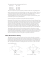
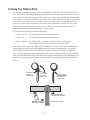
1
Falcon 3 145, 170, 195 and Tandem
Owner / Service Manual
July 2007 - Third Edition
Falcon 3 145, 170, 195 and Tandem
Copyright © 1994 through 2007 by Sport Kites, Inc. dba Wills Wing, Inc. All rights reserved.
No part of this manual may be reproduced in any form without the express written permission of
Sport Kites, Inc., dba Wills Wing, Inc.
July 2007 - Third Edition
500 West Blueridge Ave • Orange, CA • 92865 • Phone (714) 998-6359 • FAX (714) 998-0647
Internet Web address: http://www.willswing.com • E-mail: [email protected]
Contents
Introduction ...................................................................................................... 1
Disclaimer And Warning ................................................................................... 2
Technical Information And Placarded Operating Limitations .................................... 3
A Note About Platform Towing ........................................................................... 5
A Few Notes About The Falcon 3 Tandem ........................................................... 6
A Note About High Duty Cycle Operations ........................................................... 7
A Note About Parts Replacement and Parts Interchangeability ................................ 7
Falcon Breakdown Procedure For Shipping And Reassembly Procedure .................... 8
Falcon Set-Up Procedure .................................................................................. 10
Launching And Flying The Falcon ...................................................................... 21
Using Wing Tufts ............................................................................................ 21
Trimming Your Glider In Pitch ........................................................................... 24
Speeds To Fly And Using Your Airspeed Indicator ............................................... 26
Landing The Falcon ......................................................................................... 27
Falcon Breakdown .......................................................................................... 31
Falcon Stability Systems .................................................................................. 32
Maintenance Schedule .................................................................................... 34
Removing The Sail From The Airframe And Short Packing The Glider ..................... 36
Litestream Installation Procedure ...................................................................... 44
Tuning ........................................................................................................... 46
Car Top Mounting And Transport ...................................................................... 48
In Closing ....................................................................................................... 48
HGMA Compliance Verification ................................................................. 49 - 52
Frame Plans ............................................................................................ 53 - 62
Introduction
Thank you for purchasing a Wills Wing glider, and welcome to the world wide family of Wills Wing
pilots. We are a company of pilots and aviation enthusiasts, and our goal is to serve your flying needs
now and in the future, as we have done for pilots throughout the world since 1973.
We encourage you to read this manual thoroughly for information on the proper use and maintenance
of your Wills Wing glider. If at any time you have questions about your glider, or about any aspect of
hang gliding that your Wills Wing dealer cannot answer, please feel free to give us a call.
Please visit our web site at http://www.willswing.com on a regular basis. The site features extensive
information about Wills Wing gliders and products, a Wills Wing Dealer directory, a comprehensive list
of service and technical bulletins, current editions of owners manuals, our complete retail price list, a
search engine, and more. Our web site is the means by which we will communicate with you when
we have service advisories or other information related to your safety that we need to make you
aware of.
We wish you a safe and enjoyable flying career, and, once again, welcome aboard!
Rob Kells, Mike Meier, Linda Meier, and Steve Pearson
Wills Wing, Inc.
—1—
Disclaimer And Warning
Hang gliding is a form of aviation. Like any form of aviation, its safe practice demands the consistent
exercise of pilot skill, knowledge of airmanship and weather, judgment and attention at a level which is
appropriate to the demands of each individual situation. Pilots who do not possess or exercise the
required knowledge, skills and judgment are frequently injured and killed. The statistical rate at which
fatalities occur in hang gliding is approximately one per thousand participants per year.
The Federal Aviation Administration does not require a pilot’s license to operate a hang glider. Hang
gliders and hang gliding equipment are not designed, manufactured, tested or certified to any state or
federal government airworthiness standards or requirements. Hang Gliders are not required to be
registered with the Federal government. As a result, we do not have a reliable way to keep track of
contact information for the owners of Wills Wing hang gliders. It is your responsibility to check with us
periodically for safety and airworthiness advisories and information related to your glider. The easiest
way to do this is to check our web site at http://www.willswing.com Wills Wing hang gliding products
are not covered by product liability insurance. You should never attempt to fly a hang glider without
having received competent instruction. We recommend that you not participate in hang gliding unless
you recognize and wish to personally assume the associated risks.
Please fly safely.
Wills Wing, Inc.
—2—
Technical Information And Placarded Operating Limitations
This manual covers the Falcon 3 145, 170, 195 and Falcon 3 Tandem.
These gliders have been tested and found to comply with the 2006 HGMA Airworthiness Standards.
At the time of this writing - January 2007 - no application for an HGMA Certificate of compliance has
been made, and no HGMA Certificates of Compliance have been issued for these gliders. Please see
www.HGMA.net for updated information on the HGMA certification status of any hang glider.
The HGMA Certification standards require:
1. A positive load test at root stall angle of attack at a speed equal to at least the greatest of:
a. 141% of the placarded maximum maneuvering speed
b. 141% of the placarded maximum rough air speed
c. 123% of the placarded speed never to exceed
for at least three seconds without failure.
The required speed for this test was 59 m.p.h..
2. A negative 30 degree angle of attack load test at a speed equal to at least the greatest of:
a. 100% of the placarded maximum maneuvering speed
b. 100% of the placarded maximum rough air speed
c. 87% of the placarded speed never to exceed
for at least 3 seconds without failure.
The required speed for this test was 42 m.p.h..
3. A negative 150 degree angle of attack load test at a speed equal to at least the greater of 30 mph
or 50% of the required positive load test speed for at least 3 seconds without failure.
The required speed for this test was 30 m.p.h..
4. Pitch tests at speeds of 20 m.p.h., 34 m.p.h. and 48 m.p.h. which show the glider to have a
positive pitching moment coefficient over a range of angles of attack from trim angle to 20
degrees below zero lift angle at 20 m.p.h., and from trim angle to 10 degrees below zero lift angle
at 34 m.p.h., and from 10 degrees above zero lift angle to zero lift angle at 48 m.p.h.
5. Flight maneuvers which show the glider to be adequately stable and controllable throughout the
normal range of operation.
The Falcon 3's have been designed for foot launched soaring flight. They have not been designed to be
motorized, tethered, or towed. They can be towed successfully using proper towing procedures. Pilots
wishing to tow should be USHGA skill rated for towing, and should avail themselves of all available
information on the most current proper and safe towing procedures. Suggested sources for towing
information include the United States Hang Gliding Association and the manufacturer of the towing
winch / or equipment being used. Wills Wing makes no warranty of the suitability of the glider for towing.
Flight operation of the Falcon should be limited to non aerobatic maneuvers; those in which the pitch
angle will not exceed 30 degrees nose up or nose down from the horizon, and the bank angle will not
exceed 60 degrees. The Falcon is generally resistant to spinning, but will spin from a stalled turn at
—3—
bank angles of 40 degrees or more, or if the pilot applies positive pitch control aggressively in combination with roll control input so as to roll towards the high wing. Recovery from a spin requires unstalling
of the wing, and it is therefore important that in the event of a spin, no application of nose up pitch
control be held. The Falcon will recover from a spin once control pressures are relaxed. As the nose
lowers and the angle of attack is reduced, the stall will be broken and the spin will stop. However,
such recovery will consume significant altitude, and will result in the glider assuming an unpredictable
heading. Recovery from a spin may therefore involve a flight trajectory which intersects the terrain at
a high rate of speed. An aggravated spin could result in loss of control, in flight inversion, and structural failure. Therefore no attempt should ever be made to deliberately spin the glider.
The maximum steady state speed for a prone pilot in the middle of the recommended weight range full
forward on the control bar is approximately 42 m.p.h. for the Falcon. The placarded speed never to
exceed and maximum maneuvering speeds for the Falcons are:
Model
Falcon 3 145, 170, 195, Tandem
Vne
48 mph
Va
42 mph
The Falcon can be flown in steady state high speed flight with the pilot full forward over the bar
without exceeding the VNE speed. Abrupt maneuvers may cause the glider to exceed VNE, and
abrupt maneuvers should not be made from speeds above 42 mph.
The stability, controllability, and structural strength of a properly maintained Falcon have been determined to be adequate for safe operation when the glider is operated within all of the manufacturer
specified limitations. No warranty of adequate stability, controllability, or structural strength is made or
implied for operation outside of these limitations.
The stall speed of the Falcon at maximum recommended wing loading is 25 mph or less. The top
(steady state) speed at minimum recommended wing loading for a prone pilot with a properly designed
and adjusted harness is at least 35 mph.
All speeds given above are indicated airspeeds, for a properly calibrated airspeed indicator mounted in
the vicinity of the pilot. Such an airspeed indicator is available through your Wills Wing dealer.
The recommended hook in pilot weight range for the Falcon 3 is:
Falcon 3 145:
Falcon 3 170:
Falcon 3 195:
Falcon 3 Tandem:
120 - 190 lbs.
140 - 220 lbs.
175 - 275 lbs.
185 - 500 lbs.
Be advised that pilots with hook in weights within 20 lbs of the minimum recommended will find the
Falcon somewhat more demanding of pilot skill to fly, and that pilots with hook in weights of more than
130% of the minimum recommended will experience some relative degradation of optimum sink rate
performance due to their higher wing loading. Please note that the term "recommended hook in pilot
weight range" comes from the HGMA certification standards, and without some qualification, may be
misleading. The recommended weight ranges as listed above represent the full range of pilot hook in
weights over which the model listed will retain adequate stability, performance, control, and structural
strength. A more appropriate term for the weight ranges listed above might be the "allowable" pilot
hook in weight range. The pilot hook in weight ranges which we would actually "recommend" as being
optimum are given in the following table:
—4—
The optimum hook in pilot weight range for the Falcon 3 is:
Falcon 3 145:
Falcon 3 170:
Falcon 3 195:
Falcon 3 Tandem:
140 - 165 lbs.
165 - 200 lbs.
200 - 240 lbs.
240 - 450 lbs.
The Falcon 3 models have superior aerodynamic performance to that of the corresponding Falcon 1
models, especially at the lower end of the speed range. On average, a given size Falcon 3 will have a
1-2 mph lower stall speed, with the same pilot weight, as the corresponding Falcon 1. This allows a
heavier pilot to achieve the same, or better sink rate on the same size of the Falcon 3.
A minimum USHGA Novice (II) level of pilot proficiency is required to fly the Falcon safely, unless
under the direct supervision of a qualified instructor.
Operation of the glider by unqualified or under qualified pilots may be dangerous.
Operating the Falcon outside of the above limitations may result in injury and death. Flying the Falcon
in the presence of strong or gusty winds, or turbulence may result in loss of control of the glider which
may lead to injury and death. Do not fly in such conditions unless you realize and wish to personally
assume the associated risks. Wills Wing is well aware that pilots have, and continue to perform
maneuvers and fly in conditions which are outside the recommended operating limitations stated
herein. Please be aware that the fact that some pilots have exceeded these limitations in the past
without dangerous incident does not imply or insure that the limitations may be exceeded without risk.
We do know that gliders which meet all current industry standards for airworthiness can and do
suffer in flight structural failures, both as a result of turbulence, and as a result of various maneuvers
outside the placarded operating limitations, including, but not necessarily limited to aerobatics. We do
not know, and cannot know, the full range of maneuvers or conditions which may cause the pilot’s
safety to be compromised, nor can we test the glider in all possible circumstances.
A Note About Platform Towing
When platform towing, it is necessary to attach a nose line to the front of the glider, to restrain the
glider at the proper pitch attitude while on the tow platform. If the noseline is installed improperly, it is
possible for it to cause the bottom front wires to become detached from the nose of the glider as the
glider departs the platform during launch, which will result in a complete loss of control of the glider
and a very dangerous crash. Please see the diagrams below for the correct way and one incorrect
way to install the nose line.
Correct Attachment
Incorrect Attachment - Unsafe!
—5—
When routed incorrectly, the nose line is simultaneously pulling down on the keel, and forward on the
front wires and/or tang - which is exactly what is required to disengage the tang from the keyhole
collar. In addition, because the nose line also normally pulls forward from the nose of the glider, it will
normally restrain the front wires in approximately the normal position, until tension on the nose line is
released upon launch from the platform. As a result, it may not be apparent that the front wires have
become disconnected, or are in danger of being disconnected from the nose.
Please note that the nose line must not be routed in any way such that it can pull
forward on the nose wires or the nose tang. The incorrect routing shown is one
example of a way in which this could happen. It could also happen, however, if the
nose line is routed outside the V of the wires, but behind the tang handle.
Please note that the button safety lock may not be effective in preventing the nose
wires from being disconnected by an improperly routed nose line. Make sure that the
nose cone is not installed in such a way as to depress the button lock.
All pilots planning to platform tow using a Wills Wing glider fitted with the keyhole
tang nose catch must, as their last checklist item prior to "going to cruise," positively verify that the nose line is not routed in such a way that there is any possibility
that it can cause the nose wires to disconnect.
A Few Notes About The Falcon 3 Tandem
Federal Aviation Regulation FAR Part 103 - Ultralight Vehicles - which governs the flight operation of
hang gliders in the United States - restricts the operation of any ultralight vehicle to a “single occupant.” The United States Hang Gliding and Paragliding Association has obtained an exemption to the
“single occupant” requirement of FAR Part 103 which allows for two place, or “tandem” flying in a
hang glider. Pilots operating under this exemption must be individually authorized to do so by the
exemption holder, and must operate under all of the requirements of the exemption in order to conduct
legal two place flight operations. It is the pilot’s responsibility to have the necessary skills, knowledge
and experience, to obtain the proper authorization to operate under the exemption, and to operate
under the requirements of the exemption. Tandem or two place hang glider flight requires special skills,
experience and knowledge that are far beyond what is required for single place operations. Based on
flight testing and other testing conducted by Wills Wing on the Falcon 3 Tandem glider, we believe that
the Falcon 3 Tandem is suitable for two place flight, provided that the pilot in command has all the
necessary knowledge, skills and experience to conduct such flight operations safely, and follows all
appropriate procedures for safe two place flight. The Falcon 3 Tandem model can also be flown single
place by a pilot within the recommended weight range, and in the case of single place operation, a
minimum USHGA Novice (II) level of pilot proficiency is required to fly the Falcon 3 Tandem safely,
unless under the direct supervision of a qualified instructor.
This information covers only the Falcon 3 Tandem - see the appropriate Owner/Service Manuals for
important information about previous Falcon Tandem and Falcon 225 models.
—6—
A Note About High Duty Cycle Operations
Gliders which are used in a training environment, or in any situation which involves a high number of
flight operations over short period of time, will require an accelerated maintenance program in order to
maintain adequate airworthiness. The design and testing of these gliders does not necessarily take into
account the types of wear which may result from high duty cycle operations. The operator must take
responsibility to thoroughly and adequately inspect the glider to determine whether maintenance is
being conducted on a schedule appropriate to maintain the airworthiness of the glider.
A Note About Parts Replacement and Parts Interchangeability
Falcon 1's, Falcon 2's and Falcon 3's share a number of parts, but many parts are different. In addition,
there are configuration variations within a given model line. When ordering replacement parts, it is
very important to provide the glider serial number to insure that the correct replacement parts are
provided. The serial number is a five digit number, beginning with the number 2, and can normally be
found in three places on the glider - written inside the nose of the sail (most reliable), on an adhesive
label on the bottom of the keel at the nose, and written on the operating limitations placard on the
bottom of the rear of the keel. Please also note that some configuration options - such as basetube
type, (straight vs. speedbar, or .095 wall vs. .065 wall), or optional Litestream Control Bar, may have
changed since the glider was produced, so it is necessary to specify this information when ordering
these parts.
—7—
Falcon Breakdown Procedure For Shipping And Reassembly Procedure
The Falcon 3 can be broken down to approximately 2/3 of its normal length by removal of the rear
leading edges. Alternately, the Falcon 3 145, 170 and 195 can be short-packed to less than a seven
foot length, by removing the sail and further disassembling the airframe. This section of the manual
covers the 2/3 length breakdown and reassembly procedure. Note that the procedure for the Falcon 3
Tandem is slightly different, due to differences in the leading edge construction. The different procedures for the Falcon 3 Tandem are specified in each section of the instructions.
To break down the leading edges follow these steps
1. Lay the glider on the ground or floor, unzip and remove the bag and remove the velcro ties. Undo
the velcros that hold the sail around the aft end of the rear leading edge at the rear sail mount and
pull the sail rearward at each tip to dismount the sail from the rear leading edge. You may use a
large, flat bladed screw driver to pry the sail mount webbing away from the slotted endcap. Take
care that the screwdriver does not have a sharp edge which might cut or damage the webbing.
2. Obtain an indelible marker. Check to see if the rear leading edges are labeled left and right. If they
are not, mark the rear leading edges left and right (remember that left and right are reversed if the
glider is lying “on its back”, upside down.
3. On the Falcon 3 145, 170, or 195, the junction of the rear leading edge and front leading edge is
aft of the leading edge / crossbar junction. The forward edge of the rear leading edge is slotted,
and this slot engages on a clevis pin in the rear portion of the oversleeve on the front leading
edge. Pull the rear leading edge straight aft to disengage it from the front. On the Falcon 3
Tandem, the junction of the rear and front leading edges is forward of the leading edge / crossbar
junction (the reinforcing sleeve is internal instead of external, and is attached to the rear leading
edge instead of the front.) To disengage the rear leading edge, first disassemble the leading edge /
crossbar attachment by removing the safety ring, castle nut and bolt. Reinstall the bolt, nut and
safety ring, with the wires attached, in the crossbar end. (Note: You will want to replace this
safety ring with a new one when you reassemble this junction, as the original ring will normally be
distorted by the removal.) Next remove the clevis pin and safety ring located just forward of the
visible splice in the leading edge (eight inches forward of the leading edge / crossbar junction),
and pull the rear leading edge aft to disengage it from the front. Reinstall the clevis pin and
safety. In all cases, cover the sharp edges of both the front and rear leading edge tubes with
padding to protect the tubes and the sail from damage during transport.
4. Lay the mylar pockets flat so as to avoid creasing the mylar when you fold over the rear portion
of the sail. Replace the sail ties loosely, zip up the bag, and carefully fold the rear of the glider over
against the front.
Remounting the rear leading edges
1. Set the glider on its back (upside down). Unfold the glider, open the bag and lay the sail out full
length. Make sure you are mounting the correct leading edge rear into the correct front (check the
“right” / “left” designation, and remember that left / right are reversed when the glider is lying
upside down, on its back).
2. Wipe the forward six inches of the rear leading edge with a clean cloth to remove any dirt or grit.
—8—
3. Slide the rear leading edge tube into the sail, and then into the front leading edge, as far as it will
go until you encounter a hard stop. This will be the forward edge of the rear leading edge
contacting the clevis pin in the front leading edge
4. On the Falcon 3 145, 1770 and 195, rotate the rear leading edge so that the washout tube receptacle faces inwards, towards the opposite leading edge, and then continue to rotate the leading
edge slowly so as to rotate the washout tube receptacle towards the ground (“upwards” relative
to the glider), while maintaining forward pressure on the rear leading edge, until you feel the rear
leading edge slide forward as the slot in the rear leading edge engages on the clevis pin. Verify
that the rear leading edge is as far forward as it will go, and that it is locked against rotation by
the engagement of the slot on the clevis pin.
On the Falcon 3 Tandem, remove the clevis pin and safety in the front leading edge, and slide the
rear leading edge all the way forward. Rotate the rear leading edge so that the washout tube
receptacle faces inwards, towards the opposite leading edge, and then continue to rotate the
leading edge so as to rotate the washout tube receptacle towards the ground until the clevis pin
holes line up. Re-install the clevis pin and safety, taking note that the safety is installed on the top
of the leading edge (which will be on the bottom, at this point, because the glider is upside down).
On the Falcon 3 Tandem, re-assemble the leading edge / crossbar junction. Refer to the diagram,
(note that the diagram depicts the assembly right side up, whereas you will be working on it upside
down), and note that the bolt is installed from below, with the castle nut and safety ring installed on
top of the crossbar. Install a new safety ring at this time, and make sure that it is not deformed at
the split in the ring in such a way that it could catch on the sail. It is very important that the bolt be
installed in the proper direction, and that the ring is not deformed. If the bolt is installed upside
down, the ring can be caught by the sail and pulled out, which could allow the junction to come
apart in flight. Make sure also that the top and bottom side wires are properly routed
5. Remount the sail to the rear leading edge, making sure to align the inner sail mount webbing (NOT
the outer webbing handle!) squarely in the slot and attach the securing velcros. Make sure the sail
is properly oriented—the velcros should be on the inside of the leading edges.
You may find it helpful to use a large, flat bladed screw driver to pry the sail mount webbing over the
end of the leading edge tube and into the slot. Take care not to damage the webbing. Alternately, first
remove the sail mount screws located at the front of each leading edge to release the tension. The sail
mount screws may be difficult to replace until after the glider is completely assembled. Spread the
wings carefully and incrementally while pulling the sail forward at the nose during assembly to prevent
damage to the sail.
—9—
Falcon Set-Up Procedure
The Falcon has been specially designed to set up quickly and easily either on the control bar or flat on
the ground. We will first cover the steps for setting up on the control bar.
1. With the glider in the bag, lay the glider on the ground, zipper up, with the nose into the wind. If
there is more than five mph of wind, or if the wind is gusty, turn the glider slightly more than 90
degrees to the wind direction.
2. Undo the zipper, remove the battens, and remove the control bar bag.
3. Separate the control bar legs.
a. Remove the safety ring, speed nut and bolt from the corner bracket.
b. Insert the basetube into the corner bracket so that the holes line up.
c. Install the bolt, nut and safety, securing the bracket to the basetube.
Make sure that the bolt passes through both the bracket and the basetube, thus
securing the basetube to the bracket. Proper orientation of the basetube during
installation will result in the "Wills Wing" sticker being on top of the basetube and
right side up when viewed while hooked into the glider in the normal flying position.
Do not insert the basetube into the fitting at an angle, and do not force the fitting onto the
basetube if it does not slide on freely. Check for dirt or damage to the inside of the fitting or the
outside of the basetube. If the fitting is forced onto the basetube, it may be impossible to
remove. See your dealer if the fitting becomes difficult to install or remove. If your glider is
equipped with a Litestream control bar, attach the basetube to the downtubes by aligning the
downtube bottom end plug fittings into the gap in the basetube end brackets, and installing the
ball lock pins. Make sure that the ball lock pins are inserted fully into the basetube bracket,
otherwise they may not be secure.
4. Flip the glider upright and set it on the control bar, and remove the glider bag and all Velcro sail ties.
5. Spread the wings almost all the way. Raise the kingpost to a vertical position, checking to make
sure that the top front and top side wires are not wrapped around the kingpost.
— 10 —
6. Attach the bridle ring to the snap hook at this time, taking care that there is not a twist or rotation
in the bridle ring which causes the bridle lines to cross over one another.
7. Lay out the battens and check each batten for symmetry against the corresponding batten from
the other wing. Wills Wing convention is that black tipped battens go in the right wing and
white tipped battens in the left, except for the straight #1 plug-on battens which may both have
the same color tips.
8. Install the 2 longest cambered top surface battens in the sail. Do not engage the lever tips in the
trailing edge at this time. Order of batten insertion is longest to shortest, from the root out. Spread
the wings all the way and check all cables for any twisted thimbles or tangled cables.
9. At the rear of the keel, tension the crossbar by pulling on the rope loop which is attached to the
sweep wire keyhole tang. Drop the keyhole tang all the way down over the top portion of the
keyhole collar, and let it slide forward into the locked position. The button lock should snap up into
place behind the rear end of the tang. Next attach the keyhole tang for the top rear wire, and
again verify that the button lock snaps into place behind it.
Never install the keyhole tangs onto the keyhole collar without making absolutely
sure that they are fully engaged on the narrow neck of the collar and slid forward
into the fully locked position. An in-flight disengagement of this attachment will
cause a complete loss of structural support of the glider and a total loss of control.
10. Remove the tip cover bags, and install the remaining cambered battens. Secure the number two
batten (shortest cambered batten) with a double purchase attachment of the batten string. At this
time, you can engage all of the lever tips in the trailing edge hem, using the following procedure.
First unlock the catch on the lever portion of the tip by squeezing upwards on the bottom of the
lever portion, just behind the catch, while applying a slight downward pressure to the lever tip. This
will release the catch and allow you to pivot the lever section upwards. Next fit the end of the
lever portion into the gap in the trailing edge hem, as shown, and then rotate the lever portion
— 11 —
down until it clicks into place. Note that the locking catch on the lever portion of the tip can be
broken if the catch is not released properly before the lever is rotated upwards. If this happens,
simply replace the lever portion by snapping the old one off at the hinge point and snapping a new
one on. Note that the forward portion of the lever tip is threaded into a threaded insert in the rear
of the batten, and that the tip can thus be turned in, or turned out to adjust the overall length of the
batten and the tension the batten places on the sail. The battens should not be adjusted so as to
apply excess chordwise tension to the sail - especially on those battens inboard of the crossbar
junction. On these inboard battens, when snapping the lever down into place, you should not feel
any noticeable tension until just before the lever straightens out and snaps into place, and even
then the tension should be very light. On the number three batten, just inboard of the shortest
cambered batten which is restrained by a double loop of leech line, the tension on the lever tip
should be somewhat higher. The adjustment of the string tension on the number two batten should
be firm.
11. Install the washout tips, by plugging them straight into the receptacles in the back side of the
leading edge tube. Make sure they are inserted as far as they will go, and that there is tension on
the bungee holding them in place. Verify that the transverse batten that the washout tube supports
is properly located and secure in the sail, between the number 2 and number 3 battens. Install the
— 12 —
straight plug-on #1 battens. Insert one end of the batten through the gap in the stitching in the
bottom surface seam. This end plugs onto the stud on the back side of the leading edge, and the
batten string is secured by a double purchase to the other end.
12. At this time preflight the following from the open end of the wingtip:
a. The sail mount webbing - make sure that the inner loop of webbing is laying flat in the
bottom of the slot in the sail mount endcap.
b. The number one batten clevis pin. Note that on Falcon 3’s assembled prior to 9/8/2006,
the pin is installed from the front side of the leading edge tube, and is secured with a push
nut flush against the back side of the leading edge tube, and that there is no retaining
washer on the pin, no sleeve over the pin, and no safety ring in the pin. Because of the
manner in which the batten is held in place, these are not necessary to retain the front of
the batten. However, it is possible for the pin to be pushed back into the leading edge tube
from the backside if the push nut fails to hold it. On Falcon 3’s assembled after 9/8/2006,
the pin is installed from the backside of the leading edge tube, and is stood off from the
tube surface by a short, 1/4 inch diameter sleeve, and secured on the front side of the
leading edge tube with a small safety ring covered by protective tape. If you have a
problem with the earlier configuration, we recommend that you convert to the later
assembly. Note also that the number one batten can become disengaged in flight, if the
retaining string is too loose. The string should be adjusted as tight as it can be, without
being so tight that it slackens the sail mount webbing or pulls the webbing away from the
slot in the endcap.
13. Go to the nose and attach the keyhole tang securing the bottom front wires, by pulling down on the
nose of the glider while pressing the tang upwards over the shouldered bolt. (Remember it is the
pulling down of the glider’s nose rather than the upward pressure on the tang that allows you to
install the tang over the bolt. If you have difficulty installing the tang, and no wires are twisted or
thimbles cocked, it is probably because the glider is not sitting on level ground.)
— 13 —
14. Make sure that the spring loaded button lock pops up behind the tang, securing it in place.
15. Push the nose batten fully back into the sail and lift the open end of the batten onto the stud on the
top of the keel. Look into the noseplate and preflight the top front wire. Preflight each of the
lockuts on the bottom of the noseplate - make sure they are tight, and that the bolt extends at least
one full thread beyond the nut.
Install the nosecone by pulling the bottom tabs forward and down around the nose, and mating the
velcro surfaces on the tabs to those on the sail. Make sure that the nosecose lies as flat as possible,
and does not depress the button lock safety feature securing the bottom front wires. (Note - If you
hear a flapping sound after launch, it may be that you have forgotten to secure the nosecone. If this
happens, don't panic - fly the glider at moderate speed to a safe landing.)
16. Conduct a complete preflight of the glider, according to the following procedure, checking all
assemblies which have not already been checked. Every bolt, nut, pin, safety ring, and fastener of
any kind should be checked during every pre-flight. A full pre-flight inspection should precede
every flight you make, not just the first flight of the day.
Along the left leading edge
Check that the mylar insert is lying flat in the mylar pocket, and that it is not severely creased
or buckled. A sharp crease in the mylar insert could cause a premature stall, or stall hysteresis
(delayed stall recovery) that can adversely affect both handling and performance.
— 14 —
Check the nut which secures the leading edge crossbar bracket to the leading edge, and check
the nut and safety ring which secures the crossbar to the bracket. Check that the sail is not
caught on the crossbar end, nor on the safety ring, nor on any of the hardware.
Check that there are no cocked thimbles on either end of either bottom side wire, or on the
crossbar end of the top side wire.
While pushing up on the leading edge between the nose and the crossbar junction, step on the
bottom side wire with about 75 lbs. of force. This is a rough field test of the structural security
of the side wire loop, the control bar, the kingpost, and the crossbar, and will likely reveal a
major structural defect that could cause an in-flight failure in normal operation.
Check that the mid-crossbar clevis pin and safety ring are installed.
— 15 —
At the left wingtip
Check the proper installation of the number one batten, and the sail mount webbing. Check the
proper installation of the washout tip and the proper position of the transverse batten.
Along the trailing edge, left wing
Check that there are no tears in the sail material along the trailing edge.
Check that all lever batten tips are properly engaged in the trailing edge hem and snapped into
the locked position and that the batten strings on the number one and number two battens are
properly secured.
Check that the bridles are properly engaged, with the plastic retainer balls fully seated against
the grommet.
From the rear keel
Check the nut on the top of the kingpost base bracket which secures the bracket to the keel.
Check the 1/4" solid rivet, under the webbing sock at the base of the kingpost, that secures
the kingpost to the bracket..
— 16 —
Check the condition of the sweep wires in the vicinity of the kingpost base bracket.
Check the kingpost top for proper attachment and routing of the bridles and condition of the
top rear wire and bridle pigtail wire.
Check again that the keyhole tangs are fully engaged on the keyhole collar and that the button
lock is properly engaged. Check that the bolt securing the bottom rear wires is fully engaged
in the nut in the keyhole collar, and that the collar is securely fastened. Check that the sail
mount at the rear of the keel pocket is properly attached.
Along the trailing edge, right wing
Same as for left wing.
At the right tip
Same as for left tip.
Along the right leading edge
Same as for left leading edge.
Under the glider, at the control bar
Sight down the downtubes, making sure that they are straight.
— 17 —
Check the cables at the control bar corners, making sure that all six cables are properly
secured and that there are no kinks or twisted thimbles. Check for proper installation of all
bolts, nuts, pins and safety rings at the control bar corners.
Verify that both ends of the basetube are properly and securely attached to the basetube end
bracket, and that the speed nuts and safety rings are in place on the securing bolts.
Check the control bar apex bracket hardware, including the clevis pin safeties, the control bar
top plug bolts and nuts, and the elbow to apex bracket nut and bolt.
Check the main and backup hang loops, that they are properly installed in the proper position
and that they are in good condition.
Check the attachment of the sweep wire to the crossbar, and the center hinge bolt and nut.
At the nose
Check the security of all nuts at the noseplate, and check the top front wire. Check that the
keyhole tang safety is properly secured that the button lock is in place and that the nose cone
is properly installed.
— 18 —
Laying the glider down flat
Once the glider is assembled it can easily be laid down flat on the ground.
1. Disengage the nose cone from the bottom surface attachment, press upwards on the nose tang
button lock, and disengage the keyhole tang by pulling down on the nose plate while pressing
forward on the tang handle.
2. Rock the glider forward so that the basetube folds rearward and underneath the glider as you
gently lower the glider to the ground.
Reverse the procedure to set the glider upright again.
Setting the glider up flat on the ground
In areas where the ground is not rocky and when there are strong winds, you may wish to set up the
glider flat on the ground. This is easy to do, and relatively few parts of the set up procedure are
different from what has been described.
1. After unfolding and securing the control bar, flip the glider over right side up with the control bar
still flat under the glider, and folded to the rear.
2. Spread the wings, attach the bridle ring and install all the battens and the washout tips. (Note:
Perform all the normal preflight operations as described above).
3. Tension the crossbar.
4. When ready, raise the nose of the glider while pulling on the bottom front wires to raise the glider
up onto the control bar. Secure the bottom front wires as described above.
— 19 —
Falcon 3-views
— 20 —
Launching And Flying The Falcon
1. If the wind is more than 10 mph or gusty you should have an assistant on your nose wires on
launch, and, if necessary, an assistant on one or both side wires. Make sure all signals are clearly
understood. Do a hang check immediately prior to launch. The angle at which you hold the glider
should depend on the wind speed and slope of the terrain at launch; you want to achieve a slight
positive angle of attack at the start of your run.
2. Run aggressively on launch and ease the bar out for lift off.
3. The flying characteristics of the Falcon are typical of a medium performance flex wing. Make
your first flights from a familiar site in mellow conditions to give you time to become accustomed
to the glider.
4. We recommend that you hang as close as possible to the basetube in the glider - this will give you
lighter control pressures and better control.
Using Wing Tufts
Your Wills Wing glider has been equipped from the factory with short yarn tufts on the top surface of
each wing. The shadow of these tufts will be visible through the sail. The tufts are useful for indicating
the local reversal of the airflow which is associated with the onset of the stall in that portion of the
wing. You can use these tufts, as described below, to help determine when you are flying at minimum
sink airspeed.
There are two important airspeeds with which all hang glider pilots should be intimately familiar;
minimum sink airspeed (hereinafter referred to as VMS) and minimum controllable airspeed (MCA).
The most important of these two is MCA. Minimum sink airspeed is that speed at which your descent
rate is the slowest possible. It is the speed to fly when you want to maximize your climb rate in lift, or
slow your rate of descent to a minimum in non lifting air. (You would normally not fly at VMS in
sinking air; the strategy there is normally to speed up and fly quickly out of the sink. By minimizing
your time spent in the sinking air you minimize altitude lost, even though you have momentarily increased your sink rate by speeding up.)
Minimum controllable airspeed is that speed below which you begin to rapidly lose effective lateral
control of the glider. Recognition of this speed and its implications is a more subtle problem than many
pilots realize. We have seen several instances of pilots who were having a lot of trouble flying their
gliders simply because they were unknowingly trying to fly them too slowly; below the speed at which
the glider responded effectively to lateral control inputs. It is our opinion that a great percentage of
hang gliding accidents are caused by inadvertent flight below MCA, and subsequent loss of control of
the glider with impact preceding recovery. Such incidents are usually attributed to “stalls,” but it is not
the stall per se that causes the problem, indeed the glider need not even be “stalled” in the traditional
sense.
There is no necessary cause and effect relationship between minimum sink speed and minimum
controllable airspeed. VMS is determined primarily by the wing loading and span loading, the wing
planform, the wing section characteristics, etc. MCA is influenced most heavily by the tension in the
sail; how much “billow” the glider has. However, in your Wills Wing glider, as in most hang gliders,
MCA and VMS evolved towards a common value during the design and development of the glider.
— 21 —
This is so because if the wing is tuned so tight that minimum controllable airspeed is at a higher speed
than minimum sink speed, then effective sink rate performance can be improved by loosening the wing
so as to lower the minimum controllable airspeed. Conversely, if minimum controllable airspeed is
reached at a speed below that of minimum sink, the wing can usually be tightened so as to improve
glide performance without significant sacrifice in other areas.
Using wing tufts to find the minimum sink speed of your glider
On a flex wing hang glider, the wing experiences a gradual and progressive stall, and different
spanwise stations of the wing stall at different angles of attack. Contrary to popular belief, a hang
glider wing usually does not stall first in the root or center section. It is true that because of wing twist
the root section is at the highest angle of attack relative to the remote free stream airflow, but other
factors influence the stall propagation on the wing. Specifically, a flex wing hang glider usually stalls
first somewhere outboard of the root on each wing, approximately one fifth to one third of the way out
from the root to the tip, in the area where your tufts are located. As the angle of attack is raised
further, the stall propagates both outward towards the tips and inward towards the root. If you wish to
observe the stall propagation across the whole wing on your glider, you can cut some more tufts from
knitting yarn, about 3-4" long, and tape these to the top surface of your sail across the rest of the span.
During normal flight the flow will be chordwise along the wing, and the tufts will point towards the
trailing edge. When the wing stalls, the tufts will reverse direction, indicating the local flow towards the
leading edge.
At the first onset of stall, the tufts will indicate the impending separation by first wiggling, and then
deflecting spanwise, before they fully reverse and point forward. The first onset of stall occurs well
before the familiar “stall break” in which the glider pitches uncontrollably nose down to recover from
the stall. By the time the stall break occurs, all tufts but those farthest outboard and those farthest
inboard will have indicated reversed flow.
The first onset of midspan stall as indicated by the first tickling of the tufts indicates that you have
reached the angle of attack corresponding to the glider’s minimum sink airspeed. This will also be very
close to the glider’s minimum controllable airspeed. To find the glider’s minimum sink speed, fly the
glider in smooth air, early in the morning or late in the afternoon. When you are well away from the
terrain, and well clear of other aircraft, look up at the wing tufts while you very gradually reduce the
— 22 —
speed of the glider. Note the speed at which the first tuft first begins to wiggle just prior to blowing
spanwise toward the tip. (If the tufts contain static electricity, they may not show this lateral wiggle
prior to reversal. However, you may get other clues to the beginning of separation, such as slight
flutter or rumble in the top surface of the sail.) This is your speed for minimum sink rate. Familiarize
yourself with the position of the control bar relative to your body at this speed, with the sound and feel
of the wind, with the reading on your airspeed indicator, and with the feel of the glider in terms of pitch
and roll pressures. Most of the time when you are flying it will not be practical to look up for extended
periods of time at your tufts. That is why familiarization with these other, more accessible indicators is
important.
After finding your minimum sink speed, experiment with roll control response at speeds just above and
just below this speed to find the value of MCA and the corresponding bar position and other indicators
for this speed. Realize that your effective MCA is going to be higher and higher as the air becomes
more and more turbulent; control response that is perfectly adequate in smooth air will not be good
enough in rougher air. Try flying the glider with the midspan tufts fully reversed; you will probably find
that the glider is somewhat controllable, but only with a lot of physical effort. Note that both MCA and
VMS come well before the glider actually “stalls” in the traditional sense, i.e. pitches uncontrollably
nose down. You may also be able to sense, or your vario may tell you that although the glider has not
“stalled” (pitched nose down) your sink rate has increased significantly. In this mode the glider is
“mushing.”
Once you have familiarized yourself with the glider’s characteristics in this range of speeds, you will
not need to look at the tufts very often. You will know from bar position and bar pressure, and from
the sound and feel of the relative wind when you are at your minimum sink / minimum controllable
airspeed. In general, you should not fly your glider below this speed. Be aware, however, that when
you are flying at minimum sink in thermal gusts and turbulence, you will experience gust induced
separation of the airflow which will periodically cause the tufts on your sail to reverse.
Of course in a turn, your minimum sink speed goes up because you are banked, and the bank effectively increases your wing loading which increases your flying speed for any angle of attack. But note
this: The tufts indicate angle of attack, without regard to airspeed! Therefore, if you practice
flying various bank angles in smooth air (while well away from any terrain or other gliders) and watch
your tufts (on the inside wing, which will be at the highest angle of attack) you will get a feel for the
way your minimum sink speed varies at varying bank angles.
One final caution: from time to time a tuft may to stick completely to the sail, and fail to properly
indicate the direction of local flow. This may result from static buildup, or from the fine threads of the
yard becoming caught on a seam or some dirt or imperfection in the sail. The tuft may stick while
indicating normal flow, but most often it will stick after having reversed, such that the tuft will indicate
a stalled condition that does not exist. One clue in this situation is to note whether or not the tuft is
wiggling. Since flow reversal occurs during a turbulent separated flow, a reversed tuft should be
wiggling rapidly. If it is not, it is probably stuck. A tuft indicating normal flow will not usually wiggle.
An occasional application of silicone spray to the tufts, and making sure that they are positioned so
that they cannot catch on any seam will minimize the problem of sticking.
— 23 —
Trimming Your Glider In Pitch
The fore and aft location along the keel of your hang point is commonly (if mistakenly) referred to as
your “CG location.” The location of this hang point will, all other things being equal, determine at what
angle of attack and airspeed your glider will naturally tend to fly (or trim), and therefore how much bar
pressure there is to pull in from trim to a given faster speed, or how much pressure there is to push out
from trim to a given slower speed. The farther forward your hang point is, the faster the glider will
trim, the less effort will be required to fly fast, and the more effort will be required to fly slow. Since
the Falcon performs best at speeds relatively close to VMS, it is usually best to trim the glider at
between minimum sink airspeed and perhaps 3 mph above that.
The pre-set factory position for the main hang loop is:
Falcon 3 145, 170
2.5 inches forward of the horizontal apex bolt
Falcon 3 195
3.25 inches forward of the horizontal apex bolt
Falcon 3 Tandem
For tandem flight, 3.25 inches forward of the horizontal apex bolt
For solo flight, 2.75 inches forward of the horizontal apex bolt
Hang loop fore and aft position is adjusted by loosening the Velcro cinch strap on the main hang loop,
repositioning the loop as desired, and retightening the cinch strap. This strap must be very tight to
insure that the hang strap does not move during set up and breakdown, or in flight. To tighten the
Velcro, grasp the hanging portion of the hang strap with your left hand and pull down while pushing up
with your left thumb on the Velcro cinch strap where it passes through the top end of the hang loop. At
the same time, pull up vigorously on the cinch strap and press it into place against the mating Velcro
surface.
Hang loop must
be passed
through itself.
Velcro is used
to cinch loop
tightly to keel.
Hang loop must be
centered on bottom
of keel when velcro
is fully cinched.
Move hang loop towards
nose to increase trim speed
Move hang loop towards
tail to reduce trim speed
— 24 —
(Back up loop not shown)
We recommend that you not stow your glider bag, or any other cargo on the glider.
The practice of attaching your glider bag to the keel, for example, can drastically
alter the pitch trim and static balance of your glider, and adversely affect its flying
and landing characteristics. The best place to carry your glider bag or other cargo
is in your harness.
In the absence of the use of tufts, it has become common for pilots to talk about bar position, or about
indicated airspeed, when trying to communicate how to trim a glider properly or how to fly a glider at
the proper speed for a given situation. The problem is that these methods are unreliable and inconsistent from one pilot to another even on the same glider. The angle at which your harness suspends your
body in your glider has a great deal to do with your perception of the bar “position” relative to your
body. Airspeed indicators vary in their indicated airspeed depending on the make of the instrument, its
calibration, any installation error, etc. The use of tufts gives you an absolute first hand indication of the
actual aerodynamic event associated with two critically important airspeeds on your glider. It is a
potentially useful tool that may improve your flying.
— 25 —
Speeds To Fly And Using Your Airspeed Indicator
The optional Wills Wing Hall Airspeed Indicator has been specially designed to help you fly your
Falcon at the proper speeds for optimum safety and performance.
Note: The Wills Wing Hall ASI is color coded for VNE and Va speeds of 53 mph and 46 mph respectively, and the description below of the color coding on the ASI references those speeds. The Falcon 3
170 and 195 have lower VNE and Va speeds of 48 mph and 42 mph. You can still use the airspeed
indicator to determine proper speeds to fly, but the top or the green region, the yellow region and the
red line are not correctly located for the Falcon 3.
There are four color coded bands on the ASI:
White: This is the range from 20 mph to 30 mph. This is the normal flying speed range. While
thermalling or flying in lift, try to keep your speed within the lower half of this range. For gliding in
light sink or light headwind, you will want to fly in the upper half of this range.
Green: The top of the green region represents the placarded maximum rough air and maximum
maneuvering speeds. This speed of 46 mph should not be exceeded except in smooth air, and no
abrupt large control deflections should be used above this speed. In heavy sink or strong
headwinds it is recommended that you keep the airspeed “in the green” for best penetration and
glide ratio over the ground.
Yellow: This region represents the upper speed range between maximum rough air / maximum
maneuvering speed and the speed never to exceed. You should fly in this range only in smooth air
as described above.
Red Line: This is your never to exceed speed. At no time should you fly faster than this speed.
Color Coding
53 mph - Red
46 - 53 mph - Yellow
30 - 46 mph - Green
The design of the Hall type airspeed indicator involves using a ram air versus static
pressure differential to raise a disc in a tapered tube against the force of the weight
of the disc. Because of this, the ASI has the following operating limitations:
— 26 —
a. It is only accurate in one G flight. If you are turning at a bank angle of more than 30
degrees, the ASI will read artificially low as a result of the G loading of the turn. Reliance
on the ASI for limiting airspeeds in high banked sustained spiral maneuvers will likely
cause you to exceed the placarded speed limitations of the glider and will compromise
your safety.
b. It is only accurate when within 15-20 degrees of the vertical orientation.
Landing The Falcon
We recommend using an aircraft landing approach (45 entry leg, downwind leg, base leg, and final leg)
whenever possible, and we suggest that you practice making your approaches with as much precision
as possible. Under ideal conditions, landing approaches are best done so as to include a long straight
final into the wind at a speed above best L/D speed. In a very limited field, or a field which slopes
slightly downhill, when landing in light wind, you may need to make your final approach at a slower
speed, perhaps as slow as minimum sink, in order to be able to land within the field. In winds of less
than 5 mph, if the slope is steeper than 12:1, you should seriously consider landing downwind, uphill; or
crosswind, across the slope. Landing attempts which require slow speed approaches, maneuvering
around obstacles or into a restricted area, or downwind or crosswind landings are not recommended
for pilots below an advanced skill level.
Standard Aircraft Approach Pattern
Entry Leg
Downwind Leg
Base
Final
The best way to avoid roll / yaw oscillations on approach is to fly your entire approach at a constant
airspeed, and to control your touchdown point by making adjustments to the shape of your pattern. In
particular, we recommend against the technique of make a diving turn onto final. This maneuver,
sometimes called a “slipping turn” is often taught to student hang glider pilots as a way to lose altitude
during the approach. While it will work reasonably well with low or medium performance low aspect
ratio gliders which have high levels of yaw stability and damping, and which are able to lose energy by
diving because of the large increase in drag at higher speeds, on a high performance glider this
technique serves only to convert the energy of altitude to energy of speed, while at the same time
suddenly increasing the glider’s sensitivity to control inputs. The result is a high probability of overshooting the intended landing point and the prospect of roll / yaw oscillations which may interfere with
a proper landing. If you develop good habits and the skills to fly precise approaches now, it will make
your transition to higher performance gliders easier later on.
— 27 —
Once established on a straight final approach, with wings level and flying directly into the wind, you
should fly the glider down to where the basetube is between three and six feet off the ground. At this
altitude, let the control bar out just enough “round out” so that your descent is arrested and your flight
path parallels the ground. The remainder of your approach will consist of bleeding off excess speed
while paralleling the ground and keeping the wings level and the nose into the wind until it is time to
“flare” for landing.
Prior to the landing flare your body position should be generally upright, but slightly inclined forward,
with your head and shoulders forward of your hips and your legs and feet trailing slightly behind. Your
hands should be at shoulder width and shoulder height on the uprights. You should be relaxed, with a
light grip on the bar, and your weight should be fully supported in your harness and not at all by your
arms. There are several options for when to make the transition from prone to this semi-upright
position. Some pilots favor going upright with both hands moving to the downtubes while still at altitude
prior to the start of the approach. Others transition at the start of the approach to a semi-upright
position with one hand on a downtube and one hand on the basetube, and complete the transition by
moving the other hand to the downtube just a few seconds prior to flare. Still others fly with both
hands on the basetube until established on final glide, and then transition one hand at a time to the
downtubes prior to flare.
Whichever method you use, there are a few important principles to observe. The first is that you
should not make any change in hand position unless you are flying at or very near trim speed. At
speeds faster than trim, you will be holding the bar in pitch against substantial force, and if you let go
to move your hand the glider will pitch up and roll towards your remaining hand. The second is that
while moving either hand, you have no control over the glider. You should move only one hand at a
time. Even so, if you can’t make the transition in the position of each hand quickly and reliably, you
should transition both hands while at altitude, before you start your approach. Otherwise, if you fail to
make a quick transition, you could be out of control close to the ground, and suffer a turbulence
induced change in heading or attitude without sufficient time to recover. Many pilots make the mistake
of trying to change position while flying fast and close to the ground, and experience a dangerous loss
of control as a result. A third principle to observe is that if you are using a “pod” type harness, you
should unzip and confirm that your legs are free to exit the harness at least 500 feet above the ground
and before you start your approach. If there is any problem finding the zipper pull, or dealing with a
stuck zipper, you don’t want to have to try to fix that problem while also flying the approach.
Finally, you should not attempt to get into a fully upright body position at any time during the landing
approach prior to the actual landing flare. Most modern harnesses will not allow you to hang in a fully
upright position without pulling yourself up on the downtubes, and this is something you should NOT
do. The mechanism by which you attain an upright position at the moment of touchdown is to execute
a strong flare, which causes the glider to slow abruptly, causing you to swing forward and into a
standing, upright position underneath the glider. The more upright you try to be prior to the flare, the
more you move your shoulders back relative to the center of mass of your body, which effectively
shortens your arms and weakens your flare authority. Keep your head and shoulders forward, and
your feet and legs back, with your body in a semi upright position, until it is time to flare, and then flare
from this position.
Once established on a wings level short final, into the wind, body semi-upright and with both hands on the
downtubes, your final concern is the timing and execution of the landing flare. The goal is to arrive on the
ground, on your feet, under control with the glider settling on your shoulders. If the wind is 15 mph or
— 28 —
more, you will not really execute a flare at all; you will simply slow to minimum flying speed, put a foot
down, and step onto the ground. In lighter winds, you will want to use some combination of a final nose
up flare, and running out your landing, in order to finish the flight on your feet with the glider settling on
your shoulders. The lighter the wind, the stronger should be both your flare and your run.
The traditional method of landing in light or no wind calls for a sharp, aggressive flare at precisely the
correct moment. This technique works fine when done correctly, but it’s not easy to get the timing just
right. Flare too early and you will climb, and then fall with the nose pitching down. Flare too late and
you won’t get the nose up enough to stop your forward motion, and the glider may nose into the
ground as you run into it from behind.
The flare timing process is made much easier by using a combination of a “crescendo flare” and a run
out of the landing. As you bleed off speed on final, flying just above the ground, you are at first letting
the control bar out towards its trim position. As the glider reaches trim speed, which will normally be
one to three mph above stall speed, you begin to gently push the bar out to keep the glider from
settling. At this point it is almost time to flare. As the glider enters the “mushing” range of angles of
attack, it will begin to settle in spite of your continuing to ease the bar out. This should be happening
well before your arms are significantly extended. At this point begin your flare by smoothly accelerating the rate at which you push out on the bar. At the same time, draw one leg forward, put a foot
down, and start to run as hard as you can. This run should be very much like an aggressive take off
run – your body should be leaning forward into the run and you should be driving with your legs. The
difference here is that while you are leaning into your run and driving forward with your legs, your
arms are extending fully from your shoulders, pushing out, and what feels like upwards, on the control
bar in an accelerating, “crescendo” flare.
Done correctly, this type of flare / run combination will bring the glider quickly to a very nose high
attitude, producing a great deal of drag and quickly arresting all of your forward motion. You will feel
the glider pulling you from behind, resisting your attempt to run, and as you slow down the glider will
settle gently on your shoulders. Even in no wind, you should not have to take more than a few steps. If
your timing is a little early, and you feel the glider start to climb, simply stop pushing out and resume
the flare when the glider again begins to settle. If your timing is a little late, your feet will touch down a
little sooner, but as long as you’re running and flaring at the same time, the glider will stay over your
head or behind you.
Note: Landing in a significant wind does not require a substantial landing flare; the pilot merely slows
to near zero ground speed and touches down. The proper flare in light or no wind conditions is a
dynamic action which causes a sudden and severe pitch up rotation of the glider. Pilots who have
trouble with the flare, and with the glider nosing over during landing, usually do so because of one of
the following problems:
— 29 —
a. Harness leg straps too long / hanging too low below the glider, and / or hands too low on the
control bar. This reduces pitch authority and prevents an adequate flare.
b. Improper body position - pilot leaning back, (away from the anticipated hard landing), with feet
extended in front. This moves the pilot’s center of mass forward ahead of his shoulders, effectively shortening the pilot’s arms and reducing flare authority. The proper position is with the pilot’s
body inclined forward, with the shoulders out ahead of the pilot’s center of mass. Thinking about
pushing “up” instead of “out” when flaring may help you to maintain the proper forward inclined
body position.
— 30 —
Falcon Breakdown
Breakdown of the glider is the reverse of assembly.
Note: Unlike gliders with tighter sails, the battens on the Falcon can be removed with the crossbar
tensioned. Always remove the battens gently so as to avoid undue wear on the batten pockets or
stress on the battens which may change their shape.
1. Set the glider at slightly more than 90 degrees to the wind direction (slightly tail wind). Detach the
nose cone from the bottom surface of the sail. Dismount the nose batten, and pull it out about 2"
past the noseplate. Remove the #1 battens and 2 shortest cambered battens, dismount the washout tips, roll the sail under at the tips, and install the tip cover bags over the sail and washout tips.
Stow the straight number one battens in the tip bags and tighten the velcro strap on the bags.
2. Depress the keyhole button lock on the bottom of the noseplate to allow the keyhole tang to be
disengaged. Disengage the tang by pulling down on the nose of the glider while pushing up with
your thumbs on the plastic tang handle.
3. Depress the keyhole button lock on the rear of the keel, and disengage the top rear wire. Pull back
on the crossbar sweep wire and disengage the sweep wire, de-tensioning the crossbar.
4. Remove the remainder of the battens. Snap each of the lever batten tips closed before stowing the
battens—otherwise the tips may become detached and get lost.
5. Fold the wings together, pulling the sail up over the top of the leading edges. Work gently here, and
alternate from one wing to the other, folding each wing in about 1/3 of the way at a time. Check to
see that the crossbar center has not fallen down between the keel and leading edge on one side. If
you meet any resistance, stop and correct the interference.
6. Detach the bridle ring from the snap hook, and lay the kingpost down forward against the keel.
7. Stow the bridle ring in the loop of bungee attached to the sail at the kingpost base. Install the
neoprene kingpost cap cover.
— 31 —
8. Pull the sail out so that there is even tension on the top and bottom layers and roll the sail towards
the keel on each side. Try to keep the mylar insert and leading edge area as smooth as possible.
9. Secure the sail with the Velcro sail ties provided, but do not apply them too tightly.
The wide, long Velcro strap is installed by passing it OVER THE TOP of the keel
tube just forward of the control bar top, and then installing it around the glider
leading edges. This holds the leading edges up away from the control bar apex
hardware.
10. Place the glider bag on the glider, and flip the glider over onto the ground.
11. Detach the basetube, fold the control bar, and install the control bar bag and keel protective
covers. (Note - The glider will fit in the bag more easily if you remove the basetube at both ends.)
12. Gather the battens so that all the cambered ends match up, put the battens in the batten bag tailend first and cinch the velcro tie on the bag. This will make it less likely for the battens to get out
of shape. Place the bag in the rear of the glider between the rear leading edges, and zip up the
bag.
Falcon Stability Systems
Stability in pitch is provided by reflex in the root section, which is determined by the lengths of the
kingpost, control bar, and front to rear top and bottom wires, and by the shape of the root battens, and
by reflex support bridles running from the kingpost to the trailing edge at the number five and six (and
seven on the Falcon 3 Tandem) battens, and by washout tips installed in the leading edge supporting a
transverse batten between the number two and three batten.
Correct attachment and proper adjustment of the bridles are critical to providing adequate stability at
low angles of attack, particularly those below the normal operating range.
Reflex bridle adjustment
The bridles are checked by measuring the supported height of the sail above the keel. The glider must
be fully assembled as if it were to be flown in order to measure the bridles. The glider must be out of
any wind that might put pressure on the sail. Place a small stand under the rear keel so that the tips
are completely clear of the ground. String a lightweight piece of thread from the rear tip of each bridle
batten, across the corresponding batten on the other wing. The height in inches of this thread above
top surface of the keel should be at least:
— 32 —
Model
Batten no. 5
Batten no.6
Batten no.7
F3
F3
F3
F3
9-3/4 inches
10-1/2 inches
11 inches
16 inches
5-3/8 inches
6 inches
6-3/4 inches
14-3/8 inches
10 inches
145
170
195
Tandem
Adjustment of the bridles requires replacing the bridle pigtail with one of a shorter (to tighten) or
longer (to loosen) length, or placing tubular shims under the sail to shorten individual bridle lines.
Improper adjustment of the bridles will affect the glider’s pitch stability and flight characteristics in the
following ways:
Bridles too loose
If the bridles are adjusted too loose, it will not affect the glider in normal flight as the bridles are
always slack in this range anyway. At angles of attack below normal flight, there will be a reduction in
pitch stability proportional to the amount by which the bridles are looser than they are supposed to be.
This stability reduction could increase the probability of a turbulence induced tumble or other in-flight
stability related loss of control.
Bridles too tight
If the bridles are adjusted too tight, it will compromise the flight characteristics of the glider. The
effects of too tight bridles are to increase roll control pressures and reduce roll rate in circumstances
where maximum control input is applied.
Other factors of glider geometry which affect bridle adjustment and effectiveness
The effective adjustment of the bridles is also affected by other aspects of the glider geometry. For
example, if the bottom side wires are too long, it will allow the wings to rise and slacken the bridles in
normal flight. If they are too short, it will pull the wings down, and tighten the bridles in normal flight.
If the top side wires are too short, it will reduce the amount the wings can “fold” downwards as the
glider unloads at low angles of attack, thereby reducing the effectiveness of the bridles.
Changes from proper length to the top or bottom side wires will also change the relative adjustment of
the inner and outer bridles to each other, and change the way they operate.
Finally, normal shrinkage of the sail over time, by reducing the spanwise distance to the bridle attachment station, will loosen the bridle adjustment, and this should be corrected. Please see the Technical
Bulletin on Reflex Bridle Adjustment And Maintenance (available in the Support section of the Wills
Wing web site at www.willswing.com) for more information on maintaining and adjusting bridles.
— 33 —
Maintenance Schedule
You should continually maintain your glider in a proper state of tune and repair to insure optimum
airworthiness, performance and flight characteristics. Failure to properly maintain your glider may lead
to a dangerous loss of strength, stability or control responsiveness of the glider. Following any mishap
that results in damage to the glider immediately have any damaged component repaired or replaced.
We recommend that you have all such maintenance work done by your Wills Wing dealer. In addition,
please follow the following maintenance schedule. Maintenance intervals are expressed in terms of
calendar months and number of flights. You should perform the indicated maintenance at whichever
comes first::
Every month or every 30 flights.
1. Check your battens on a flat level surface following the instructions on the batten diagram provided, and correct any that deviate from the pattern in accordance with the instructions.
Every six months or every 150 flights
1. Have a complete inspection performed on the glider and replace any component that shows any
wear, and any cable that shows any kinks, wear, damage, corrosion, etc.
2. Inspect all bolts for tightness, all safeties for proper installation and possible damage. Inspect
plates and fittings for damage, holes in tubes for elongation.
3. Inspect the sail for wear, tears, UV damage, loose stitching, etc.
4. Disassemble the control bar corner assemblies. Inspect the hardware fittings and the cable
terminations on the front and rear flying wires. Replace any component with indications of permanent deformation or other damage.
Every twelve months or every 300 flights
1. Have the sail completely removed from the frame, and disassemble all frame components. Inspect
every part of the glider for any damage or wear. Inspect the tubes for straightness and for signs of
corrosion. Anytime you have the sail off the frame inspect all of the batten pockets and batten
pocket terminations.
2. Replace bottom side wires and hang loops.
Special circumstances
1. Any time you suffer a crash or extremely hard landing you should have an “annual” inspection
done on your glider to insure that you find all damaged parts. If you bend a downtube, carefully
inspect all hardware at the top and bottom of the control bar for damage.
2. If your glider is ever exposed to salt water you will need to have the glider completely disassembled in accordance with the recommended annual inspection procedure. All frame parts will
need to be disassembled, including the removal of all sleeves, flushed liberally with fresh water,
dried completely, and treated for corrosion inhibition with LPS-3 or other suitable agent.
— 34 —
3. Cleaning Your Sail - Keeping your sail clean will extend the life of the cloth, however cleaning the
sail too often, or scrubbing the sail excessively will accelerate the breakdown of the stabilizing
resin in the cloth, and shorten the life of the sail. When cleaning the entire sail you should generally
use only water and a soft brush. You may clean small spots or stains with any commercial spot
remover that is labeled for use on polyester. Such cleaning agents are available at the supermarket
or drug store, or you may order a cleaning solution from Wills Wing through your dealer.
A note about cables and cable maintenance:
The cables which support the glider’s airframe are critical components of the glider’s structure, and
must be maintained in an air worthy condition. It is a general practice in the design of aircraft structures to design to an ultimate strength of 1.5 times the highest expected load in normal service. Hang
glider cables, like other structural components on the glider, are typically designed with a structural
safety factor of only about 50% above the expected maximum load. No significant loss in cable
strength can be tolerated.
A cable with even a single broken strand must be replaced before the glider is flown again. A cable
which has been bent sharply enough to have taken a permanent set (will not lie flat in a straight line
when all tension is removed) must also be replaced immediately. If it is not, subsequent tensioning and
de-tensioning of the cable will induce fatigue, and the cable will fail. In tests we have conducted, a
cable bent one time to 90 degrees, and then loaded to the equivalent of a normal flight load 100 times
(corresponding to 100 or fewer flights), failed at only 56% of its original strength.
Some degree of fatigue due to repeated bending of cables is almost unavoidable in an aircraft that is
assembled and disassembled with every flight. Bottom side wires are subject to the highest loads in
flight, and are therefore the most critical. This is why we recommend that these wires be replaced
annually, even if there is no known damage. The requirement for immediate replacement of a cable
known to have been bent or otherwise damaged supercedes this annual replacement requirement.
Replacement cables should always be obtained from the factory, or, if not from the factory, from a
reliable source known to use proper fabrication procedures. An improperly made cable may appear
perfectly OK on visual inspection, but could fail in flight at a load much below the intended design
strength of the cable. Even if the replacement cable is obtained from the factory, it should be checked
carefully for length against the cable it is replacing, and inspected carefully before being installed.
— 35 —
Removing The Sail From The Airframe And Short Packing The Glider
Many maintenance and repair procedures will require the removal of the sail from the frame. In
addition, the first step in short packing the glider to its shortest breakdown length is the removal of the
sail. Please follow these instructions when removing the sail, short packing the glider, and reinstalling
the sail. Please read all the instructions for each operation before beginning.
Note: The short pack procedures below incorporate the use of the optional short pack storage/transport container - a specially designed combination box and heavy-duty zippered bag designed to contain
and protect your glider during storage and transport in the short pack configuration. The container is
available through your Wills Wing dealer, or direct from Wills Wing.
45G-1310
45G-1311
45G-1312
BAG/BOX – GLIDER SHORT PACK 84
BAG/BOX – GLIDER SHORT PACK 78
BAG/BOX – GLIDER SHORT PACK 72
(Falcon 3 195)
(Falcon 3 170)
(Falcon 3 145)
Sail removal
You will need an unobstructed area six feet by thirty feet. Make sure the surface is clean. If it is
abrasive, like rough concrete, you should either put down a protective tarp or be extremely careful not
to scrape your sail.
1. Assemble the control bar, set the glider upright on the bar, and remove the bag, as if you were
beginning the process of setting the glider up to fly. Remove the front velcro sail tie. Spread the
wings slightly and remove the hang loops and set them aside.
2. Insert a #2 Phillips head screwdriver into the rear bolt securing the control bar apex and kingpost
base to the keel. Use a 5/16 box end wrench to loosen and remove the clinch nut that secures the
kingpost base bracket to the keel. Replace the nut on the bolt and tighten the nut one half turn so
that it does not come loose and get lost. (Note - When removing the nut, use the screwdriver to
hold the screw and turn the nut with the wrench, as opposed to trying to turn the screw.)
— 36 —
3. Remove the screw from the cap on the top of the kingpost, carefully remove the plastic kingpost
cap, and remove the bridle pigtail, top rear wire, top front wire, and both top side wires from the
kingpost top. Replace the bridle pigtail and re-install the kingpost top cap and screw.
4. Spread out the glider bag, and lay the glider on its side on the bag. Using a 1/2 inch wrench on the
keyhole collar and a 7/16 inch wrench on the bolt, remove the bolt securing the bottom rear wire
and keel pocket sail mount to the rear of the keel, store the bolt in the tang and re-install the
keyhole collar on the bolt, tightening 1/2 turn to secure it against becoming lost.
5. Detach the bottom side wires from the control bar corners. Replace the bolt in the bracket and
downtube, and tighten the nut 1/2 turn. Roll the glider directly onto its back. Remove the safety
rings and clevis pins that secure the control bar downtubes to the top plugs, and set the control bar
assembly aside. Re-install the clevis pins and safety rings in the control bar downtubes. Remove
the screws that secure the sail at the nose, and replace the screws in the leading edges. Remove
the remainder of the velcro sail ties. Spread the wings slightly, undo the Velcro tabs inside the rear
ends of the leading edges and then dismount the sail from the rear leading edges by pulling straight
aft on the webbing handles.
— 37 —
6. Pull straight aft on the rear leading edge tubes to remove the rear leading edges from the frame.
(Note - You can skip this step if you are not short-packing the glider).
7. Prop the nose of the glider up on the breakdown storage/transport box and spread the wings
slightly. Pull the crossbar sweep wire (and attached top rear wire) forward out through the keel
pocket. If there are no alignment stickers installed at the joint between the inboard and outboard
crossbars, use an indelible marker to mark a line across the splice on each crossbar and indicate L
or R (left or right) on each of the four tubes at this junction. Remove the mid-crossbar safety rings
and clevis pins.
Pull the crossbar center towards the nose of the glider, working it up and down as necessary, to
disengage the inboard crossbars from the outboard crossbars. Re-stow the clevis pins and safety
rings in the inboard crossbars. When the inboard crossbars are disengaged from the outboard
crossbars, turn the inboard crossbar assembly on its side and bring it around one side of the keel
tube to remove it from the glider.
Feed the top side wires into the sail through the holes in the top surface. Swing the outboard
crossbars to the rear to align them with the leading edges. Carefully slide the frame out through
the nose of the glider. If you encounter resistance, stop and find out what is hanging up.
— 38 —
9. If you need to send the sail into the factory for repair, first remove the bridle cables, then fold and
package the sail carefully. To detach the bridle cables from the sail, push on the end of each cable
loop at the bridle ball to make the cable loop round, and allow it to be worked free of the notch in
the bridle ball. Remove the ball from the cable and remove the bridle cable from the grommet in
the sail. When you send in the sail, be sure to include written instructions of what you want done,
your name and a phone number where you can be reached during the day.
Completing The Short Packing Of The Glider
1. If there are no alignment stickers installed at the joint between the front and mid leading edges,
use an indelible marker to mark a line across the splice on each leading edge and indicate L or R
(left or right) on each of the four tubes at this junction. Remove the safety rings and clevis pins
securing the mid-leading edges to the front leading edges, and remove the mid-leading edge /
outboard crossbar assemblies. Swing the outboard crossbars towards the nose again. Re-stow the
clevis pins and safeties in the front leading edges.
2. Remove the safety ring and clevis pin securing the rear keel to the front keel and remove the rear
keel. Re-stow the clevis pin and safety ring in the front keel.
3. Unzip the short pack bag and fold the corners of the bag down around the outside of the corners
of the box.
4. Lay the front leading edges / front keel assembly and the inboard crossbars assembly in the box.
At each stage of the packing process, use the glider's cover pads, cover bags and any additional
materials necessary to pad hardware fittings and protect the tubes from damage or abrasion.
— 39 —
5. Lay one end of the open glider bag flat over the first layer of tubes. Lay the mid-leading edge/
outboard crossbar assemblies and the rear keel in the box on top of the glider bag.
6. Fold another layer of the glider bag over this layer of tubes. Remove the basetube from the control
bar. Lay the remaining tubes in the short pack box.
7. Remove the two longest battens from the batten bag, break them down to their short pack length,
and return them to the batten bag. Lay the batten bag on top of the tubes, and fold the remainder
of the glider bag over the top.
8. Fold the sail as follows a. First fold the sail along the glider center line, laying the mylar pockets flat, one on top of
the other.
b. Then fold the body of the sail in segments over onto the mylar pockets, so that the resulting width of the folded sail equals the width of the short pack box.
c. Finally, fold the sail in lengthwise segments equal to the length of the short pack box, and
lay the sail in the top of the box.
9. Add any left over soft items on top of the sail (hang loops, any remaining cover bags, velcro ties,
etc.). Fold the protective bag back over the corners of the box, and zip up the bag. Cinch the
velcros on the bag to square up the box and compress the package to its minimum size.
Re-Assembling the Glider From the Short Pack Configuration
1. Prepare a clean, non abrasive work area, or lay down a clean protective tarp to work on.
2. Unzip the short pack bag and remove all of the contents.
3. Assemble the mid-leading edge/crossbar assemblies to the front leading edges, noting the left/right
alignment stickers or marks that you made. At the leading edge / crossbar junctions, swivel the top
and bottom side wires tangs so that they point towards the nose of the glider.
— 40 —
4. Swing the outboard crossbars towards the rear of the glider, and install the neoprene keel protectors over the ends of the tubes to protect the sail during insertion of the frame.
5. Remove the washout tubes from the rear leading edges, and install the rear leading edge tubes into
the front leading edge tubes - taking proper note of right and left, and making sure to position the
washout tube receptacle to the inside of the leading edge. Rotate the rear leading edges while
maintaining forward pressure on them until the slot on the rear leading edge engages fully on the
clevis pin of the front leading edge and the rear leading edges slide into the full forward position.
Reinstalling the sail on the frame
1. Position the sail on the floor with the keel pocket up and the wings folded over so that the leading
edges lie along the length of the root line, with the top of the leading edge lying on top.
2. Prepare the frame, making sure that the side wires are pulled forward from the crossbar leading
edge junction and are not wrapped around the frame. The outboard crossbars should be swung aft
facing the rear end of the leading edges and aligned with the leading edges.
3.
Position the frame with the bottom of the noseplate facing up and with the rear end of the leading
edges at the nose of the sail. Slide the frame into the nose of the sail, taking care not to disengage
the rear leading edges from the front, and making sure that the leading edges of the frame and the
crossbar halves pass properly into the bottom surface of the sail and not into the mylar pockets,
and that they don’t get caught at the rear of the bottom surface near the root. Feed the keel
outside the bottom surface and through each of the keel pockets. As you feed the frame slowly
into the sail, check periodically to see that none of the hardware is snagging on the sail. As the
crossbar ends reach the leading edge junction cut outs in the sail, bring them out through these
holes.
4. After the frame is fully inserted, swing the outboard crossbar halves forward.
5. Working through the crossbar cut out hole, insert the top wires through the holes in the sail, making
sure that no cable is wrapped around a leading edge or crossbar, and that no thimbles are cocked
or twisted. Pull the bottom side wires out through the crossbar cut out hole.
— 41 —
6. Feed the top front wire through the hole in the sail. Attach the sail mount tangs to the leading edge
tube with the screws near the noseplate. Prop the nose of the glider on the short pack box, and
spread the wings slightly. Position the crossbar center section as shown and feed the crossbar
center into the glider around one side of the keel.
When properly positioned, the crossbar center should lie below the keel (because the glider is
upside down) with the central nut on the center hinge bracket joint facing the floor. Install the
inner crossbars onto the outer crossbars, matching up the alignment marks, and secure by installing the clevis pins and safety rings. Feed the top rear wires and crossbar sweep wire along the
keel through the keel pockets and out the rear of the sail. Install the washout tubes as follows:
a. First make a loop as shown in the bungee.
b. Next slide the long end of the washout tube into the open end of the sail at the tip and slide
the loop onto the rear leading edge.
c. Pass the washout tube out of the sail through the hole at the receptacle, and position the
bungee forward of the washout tube receptacle.
d. Pull the remainder of the washout tube outside of the sail through the hole in the sail at the
washout tube receptacle.
7. Verify that the rear leading edges are still properly and fully mounted in the front by first pulling aft
no more than 1/4 inch, then pushing them forward until the front leading edge clevis pin bottoms
out in the slot, and then try to twist the rear leading edge to confirm that the slot is engaged and it
is locked against rotation. (You will feel some very small amount of rotational play in the slot / pin
engagement, but no more than a very small amount.) Mount the rear of the sail by pulling the
webbing anchor loops over the rear leading edge endcaps and into the slot in the endcaps.
— 42 —
Make sure you mount the inner webbing loops in the endcap slots, not the outer “handle” loops!
Make sure that the webbing lies flat and smooth in the slot, and that the sail is properly aligned
when mounted (not twisted or rotated 180 degrees). Secure the Velcro retainer tabs. Re-assemble
the control bar basetube to the downtubes at this time, taking care to make sure that the basetube
and the front and rear wires are properly oriented. Bolt the bottom rear wires to the rear of the
keel attaching the rear sail mount at the same time. Install the control bar downtubes onto the
plugs at the apex bracket, and attach the bottom side wires to the control bar corners. Flip the
glider up onto the control bar.
8. Pull the crossbar sweep wire tang out through the kingpost hole and pull tight on the sweep wire
while looking up into the sail towards the crossbar center. Correctly position the left and right
sweep wires on the proper sides of the top centerline of the keel.
Re-insert the sweep wire into the kingpost hole and down along the top of the keel into the rear
keel pocket. Install the kingpost base bracket onto the top of the keel, keeping the sweep wires
properly positioned on either side of the kingpost. Pass the top rear wire out of the rear of the keel
pocket and feed it between the left and right bridle cables and under the bridle cable ring. Remove
the kingpost top cap and bridle pigtail and place the top front, top side and top rear wires ball
swages in the kingpost top. Install the bridle pigtail in the kingpost top on top of the top rear wire,
and install the kingpost top cap and screw.
9. Spread the wings slowly and carefully, making sure that the sail does not catch on any hardware
and that there are no improper assemblies restricting the deployment of the wings.
10. If the bridles were disconnected from the sail as part of a sail repair, re-connect them to the sail at
this time. Proceed with a normal setup and complete pre-flight inspection of the glider following
the procedures set forth earlier in this manual.
— 43 —
Installing The Optional Litestream Control Bar Kit
Owners of Falcon 3 170’s and 195’s may order an optional Litestream Control Bar kit (the kit is not
available for the Falcon 3 145 or Falcon 3 Tandem).
We recommend that you have your dealer assist you in the installation of the kit.
The kit consists of:
ID
Qty
Unit
Description
Appplication
40F-1513
1
EA
BASETUBE AL LITSTR W/BRK 65/68
195
40F-1523
1
EA
BASETUBE AL LITESTRM W/BRKT 62
170
15J-2201
2
EA
STREAMLINED BASETUBE SKID
195/170
10K-3133
2
EA
PIN BALL LOCK 1/4 X 33MM GRIP
195/170
40G-1471
2
EA
LITESTREAM LEG 65 W/O BRKTS
195
40G-1477
2
EA
LITESTREAM LEG 62 W/O BRKTS
170
20G-1467
1
EA
CB PLUG SET OF 2 LITESTRM TOP
195/170
20G-1468
1
EA
CB PLUG SET OF 2 LITESTRM BTM
195/170
10C-5211
2
EA
BOLT NAS 623-4-21
195/170
10N-1740
2
EA
CLINCH NUT 1/4 MS21042-4
195/170
10G-1290
4
EA
CLEVIS PIN MS20392-2C29
195/170
10P-1100
4
EA
SAFETY RING AN 9491 SMALL
195/170
10T-1103
2
EA
SPACER AL .250 X .028 X .770
195/170
10T-4120
2
EA
BUSH SS .3115 X .028 X .850
195/170
10T-5103
3
EA
SPACER NY .560 X .320 X .187
195/170
45G-3058
1
PAIR
NEOPRENE COVER SLPSTRM LEG TOP
195/170
Before beginning the installation process, verify that all items above are present. Note that the
downtubes come fully assembled with all hardware attached, and that the items designated 10T-1103
in the above list are installed inside the bottom downtube end plugs.
Installation
The removal of the round control bar and installation of the Litestream bar can be done with the glider
folded up and in the bag, although the glider should be fully set up and a pre-flight inspection performed after the installation.
Removing the round control bar
1) Unzip the glider bag. Set the basetube aside.
2) Remove the bolts and nuts that secure the basetube brackets and bottom side wires to the control
bar downtubes. Set the brackets, bolts and nuts aside.
— 44 —
3) Remove the safety rings and clevis pins that secure the bottom front and rear wires in the
downtubes, and remove the wires from the downtubes. Set the pins and safety rings aside.
4) Remove the bolts and nuts that secure the downtube top end plugs to the elbows. Set the
downtubes, and the nuts and bolts aside.
5) The parts you have set aside will not be used in the installation of the Litestream bar, but should be
retained for re-installation of the round control bar.
Installing the Litestream control bar
1) Start by correctly identifying the left and right downtubes. The squared off part of the downtube
profile and the longer bottom wire slots go to the rear, the clevis pins are installed with the heads
on the outside and the rings on the inside, and the chord of the profile is “toed-in” relative to the
axis of the ¼ inch bolts and ball lock pins in the top and bottom fittings.
2) Install the Litestream downtubes onto the elbows at the control bar apex, using the bolts and nuts
provided on the downtubes. Note that on the right downtube, the provided nylon washer goes in
front of the control bar elbow.
3) Install the bottom front and bottom rear wires into the respective downtubes as follows:
a) Remove the safety ring and clevis pin and remove the bottom plug from the bottom of the
downtube.
b) Taking care not to induce any twisting in the wires, and maintaining the proper orientation
of the bottom front wire nose tang, insert the bottom front and bottom rear wires into the
back and front slots on the downtube, and pass them out through the bottom of the
downtube.
c) Remove the small aluminum spacer from the downtube plug and position the wires in the
hollowed area in the bottom of the plug such that they are captured by the spacer when
you re-insert it.
d) While sliding the excess wire back out through the slots in the downtube, re-install the plug
in the bottom of the downtube, and secure it with the clevis pin and safety ring.
4) Attach the bottom side wires to the downtubes as follows:
a) Remove the knurled bushing from the bottom downtube plug, taking care not to lose the
nylon washer.
b) Install the bottom side wire tang and nylon washer into the space between the ears on the
downtube bottom plug – taking care that the nylon washer is forward of the side wire
tang, that the side wire tang is oriented with the small projection on the tang at the bottom
(towards the basetube), that the wires are routed properly and do not cross over or wrap
around any other wires or components, and that no twist has been induced in the side
wires.
c) Re-install the knurled bushing, knurled portion last, into the bottom downtube plug and
press it in until it is flush with the surface of the plug.
5)
Install the basetube using the ball lock pins provided, and do a full set up and inspection of the
glider.
— 45 —
Tuning
Dismounting and remounting the sail at the tip
A number of tuning procedures require you to dismount the sail at the rear leading edge. This can be
most easily accomplished by using a large, flat bladed screw driver to pry the sail mount webbing off
of the end of the leading edge. The same technique can be used to reinstall the sail. Take care not to
damage the sail mount webbing, and when remounting the sail, be sure to mount the inner webbing in
the slot, not the outer handle webbing, and be sure that the webbing seats squarely in the slot.
CG adjustment
has already been covered in the section of this manual on using your wing tufts. Wills Wing recommends that tuning other than CG adjustment be performed by your Wills Wing dealer.
Turn trim
Turns are caused by an asymmetry in the glider. If you have a turn, first try to make the glider symmetrical in every way.
Airframe
Check the leading edges for possible bent tubes. Check that the keel is not bent to one side.
Check for symmetrical twist in the leading edges by checking for symmetry in the alignment of the sail
mount plugs.
Battens
Check the battens for symmetrical shape and batten string tension.
Sail mount plugs - adjusting sail tension and rotational alignment
The molded plastic sail mount plug fits directly into the rear leading edge. It is secured against rotation
by a sliding wedge which is forced out against the inside of the tube as the Allen screw is tightened.
The proper installation procedure for this plug is to engage the allen screw three turns into the sliding
wedge, install the plug into the rear leading edge, set the desired alignment, and then tighten the allen
screw 9 additional turns.
Shims are added to the allen screw type plug by sliding them over the end of the plug before the plug
is inserted into the leading edge. The shims are thus visible with the plug installed.
Once the allen screw type plug is installed, the rotational alignment can be changed by loosening the
allen screw to relieve the pressure of the wedge against the inside of the leading edge tube until the
sail mount plug is free enough that it can be rotated.
If you loosen the screw too much, the wedge will fall off inside the leading edge
tube, and you will have to dismount the sail to retrieve it.
— 46 —
Sail tension
Check for symmetrical sail tension on the leading edges. In order to check this, remove the sail mount
screws at the nose, detension and re-tension the xbar and sight the hem of the sail at the bottom of the
leading edge tube relative to the noseplate on each side. Sail tension is adjusted by adding or removing
shims in 1/8" or 1/4" increments to or from the sail mount plugs on the rear ends of the leading edges.
See the discussion above about the different types of sail mount plugs and how shims are added or
removed.
To remove or add shims from either plug, first dismount the sail mount webbing by pulling it free and
then to the outside of the leading edge. You can use a flat bladed screwdriver to pry the webbing off,
but take care not to damage the webbing. After dismounting the sail, first check and record the
rotational alignment by noting the position of the scribe mark on the plug relative to the scale on the
leading edge tube. Use the allen wrench provided in your spare parts kit to loosen the allen screw until
you can remove the plug. Add or remove shims as necessary, and then reinstall the plug, making sure
the alignment is correct. Nine turns of the allen screw after installation of the plug will secure the plug
in place.
Make sure to replace the sail mount screws at the nose.
Twisting a tip
After you have made everything symmetrical, if you still have a turn, you will correct it by rotating one
or both sail mount plugs. A left turn is corrected by twisting the left sail plug clockwise (twisting the
sail down at the trailing edge) or twisting the right sail plug clockwise (twisting the sail up at the trailing
edge) or both. Twist counter clockwise on either or both plugs to correct a right turn.
To rotate the sail plug, use the allen wrench provided in your spare parts kit to loosen the allen screw
thus pushing the wedge forward and releasing the plug.
If you loosen the screw too much, the wedge will fall off the end of the screw inside
the leading edge, and you will have to dismount the sail to retrieve it. Start by
loosening the screw ten turns, and then check to see if you can rotate it. If not,
loosen it one turn at a time until it can be rotated.
After rotating the plug in the desired amount in the desired direction, (see above) tighten the screw to
secure the plug against rotation. When the screw is properly tightened, there will be a slight bulge (less
than the wall thickness of the tube) in the rear leading edge tube adjacent to the screw.
Adjusting batten tension
The number one and number two tip battens on the Falcon 3 are tensioned by looping the batten string
over the notched end of the batten twice. The remainder of the battens are tensioned by the adjustment of the lever tip. The inboard battens should be fairly loose, as described in the batten installation
portion of the set up procedure. The outboard battens should be progressively more firm. The number
one batten strings should be fairly snug, but not so tight as to slacken the sail mount webbing which
mounts the sail at the tip. We have found that if the plug on #1 battens are adjusted too tight it can
increase the chance that the glider will enter a mild spin when stalled in a turn. If you experience this
tendency, try loosening the number one battens slightly.
— 47 —
Leading edge sail tension
The tension in the leading edge of the sail, adjustable by shimming as described above, will influence
the performance and handling of the glider. If the sail is mounted too loose, the performance will
deteriorate noticeably. If the sail is mounted too tight, the glider will handle poorly; it will be stiff and
slow in roll response with excessive adverse yaw and an increased tendency to spin in a stalled turn.
As the glider gets older and the sail stretches, you may need to add shims to maintain the proper
tension. Please note that adding shims may reduce the speed at which trailing edge sail flutter begins.
Car Top Mounting And Transport
Improper or careless transport of your glider can cause significant damage. You should transport your
glider on a rack which has at least three support points which span at least 13' of the length of the
glider. These should be well padded and at least four inches wide to distribute the load. Your glider
should be mounted on your rack with the control bar facing up. It should be securely tied down with
webbing straps which are at least 1/2" wide If you drive on rough roads where the glider receives
impact loads, you should take extra care to pad your glider internally when you pack it up. One special
area to pay attention to is the forward area of the glider where the crossbar center section bears
against the top of the leading edge tubes, and the kingpost sits on top of the keel. Some extra padding
inserted in this area will save wear on your airframe and sail.
In Closing
With proper care and maintenance, your glider will retain a high level of airworthiness for some years.
Because of the relatively short history of hang gliding, and the rapid advances in new designs, we do
not have a lot of information about the ultimate service life of a hang glider. We do know that ultraviolet (UV) damage to the sail from sunlight is probably the limiting factor in the life of your sail. Try to
avoid exposing your sail to sunlight any time you are not actually flying it.
We also know that there are forces in nature which can be so violent that they can result in fatal
accidents regardless of the airworthiness of your aircraft. Ultimately your safety is your responsibility.
Know the limitations of your knowledge, skill and experience, and know the limitations of your aircraft.
Fly within those limitations.
Have fun.
See you in the sky!
Wills Wing, Inc.
— 48 —
HGMA COMPLIANCE VERIFICATION SPECIFICATION SHEET
GLIDER MODEL
MANUFACTURED BY
Falcon 3 145
Wills Wing Inc.
All dimensions in inches; weights in pounds.
NOTE: These specifications are intended only as a guideline for determining whether a
given glider is a certified model and whether it is in the certified configuration.
Be aware, however, that no set of specifications, however detailed, can guarantee the
ability to determine whether a glider is the same model, or is in the same configuration as
was certified, or has those performance, stability, and structural characteristics required
by the certification standards. An owner’s manual is required to be delivered with each
HGMA certified glider, and it is required that it contain additional airworthiness information.
1. Weight of glider with all essential parts and without coverbags and nonessential
parts: 45 lbs
2. Leading Edge Dimensions
a. Nose plate anchor hole to:
1. Crossbar attachment hole
109.5
2. Rear sail attachment point 195.5 - 196.25
b. Outside diameter at:
1. Nose
2.05
2. Crossbar
2.05
c. Rear sail attachment point
1.97
3. Crossbar Dimensions
a. Overall pin to pin length from leading edge attachment point to hinge bolt at
glider centerline
96.37
b. Largest outside diameter
2.05
4. Keel dimensions; least and greatest allowable distances, whether variable through
tuning or through in-flight variable geometry, from the line joining the leading
edge nose bolts to:
a. The xbar center load bearing pin
42.75 +/- .25
b. The pilot hang loop 59.5 +/- 1.5
5. Sail Dimensions
a. Chord lengths at:
1. 3 ft outboard of centerline
2. 3 ft inboard of tip
b. Span (extreme tip to tip)
6. Location of Information Placard
Location of Test Fly Sticker
7. Recommended Pilot Weight Range
8. Recommended Pilot Proficiency
77.6
46.0
334.2
Keel
Keel
120 - 190
USHGA Novice
— 49 —
HGMA COMPLIANCE VERIFICATION SPECIFICATION SHEET
GLIDER MODEL
MANUFACTURED BY
Falcon 3 170
Wills Wing Inc.
All dimensions in inches; weights in pounds.
NOTE: These specifications are intended only as a guideline for determining whether a
given glider is a certified model and whether it is in the certified configuration.
Be aware, however, that no set of specifications, however detailed, can guarantee the
ability to determine whether a glider is the same model, or is in the same configuration as
was certified, or has those performance, stability, and structural characteristics required
by the certification standards. An owner’s manual is required to be delivered with each
HGMA certified glider, and it is required that it contain additional airworthiness information.
1. Weight of glider with all essential parts and without coverbags and nonessential
parts:
48 lbs
2. Leading Edge Dimensions
a. Nose plate anchor hole to:
1. Crossbar attachment hole
119.5
2. Rear sail attachment point
209.25 - 210
b. Outside diameter at:
1. Nose
2.05
2. Crossbar
2.05
3. Rear sail attachment point
1.97
3. Crossbar Dimensions
a. Overall pin to pin length from leading edge attachment point to hinge bolt at
glider centerline
105
b. Largest outside diameter
2.05
4. Keel dimensions; least and greatest allowable distances, whether variable through
tuning or through in-flight variable geometry, from the line joining the leading
edge nose bolts to:
a. The xbar center ball center 46.25 +/- .25
b. The pilot hang loop
63 +/- 1.5
5. Sail Dimensions
a. Chord lengths at:
1. 3 ft outboard of centerline
85
2. 3 ft inboard of tip
47
b. Span (extreme tip to tip)
358.5
6. Location of Information Placard
Keel
Location of Test Fly Sticker
Keel
7. Recommended Pilot Weight Range
140 - 220
8. Recommended Pilot Proficiency
USHGA Novice
— 50 —
HGMA COMPLIANCE VERIFICATION SPECIFICATION SHEET
GLIDER MODEL
MANUFACTURED BY
Falcon 3 195
Wills Wing Inc.
All dimensions in inches; weights in pounds.
NOTE: These specifications are intended only as a guideline for determining whether a
given glider is a certified model and whether it is in the certified configuration.
Be aware, however, that no set of specifications, however detailed, can guarantee the
ability to determine whether a glider is the same model, or is in the same configuration as
was certified, or has those performance, stability, and structural characteristics required
by the certification standards. An owner’s manual is required to be delivered with each
HGMA certified glider, and it is required that it contain additional airworthiness information.
1. Weight of glider with all essential parts and without coverbags and nonessential
parts:
53 lbs
2. Leading Edge Dimensions
a. Nose plate anchor hole to:
1. Crossbar attachment hole
133
2. Rear sail attachment point 228.5 - 229.25
b. Outside diameter at:
1. Nose
2.05
2. Crossbar
2.05
3. Rear sail attachment point
3. Crossbar Dimensions
1.97
a. Overall pin to pin length from leading edge attachment point to hinge bolt at
glider centerline
117.25
b. Largest outside diameter
2.44
4. Keel dimensions; least and greatest allowable distances, whether variable through
tuning or through in-flight variable geometry, from the line joining the leading
edge nose bolts to:
a. The xbar center ball center
b. The pilot hang loop
5. Sail Dimensions
48.75 +/- .25
66.75 +/- 1.5
a. Chord lengths at:
1. 3 ft outboard of centerline
2. 3 ft inboard of tip
92
47
b. Span (extreme tip to tip)
392
6. Location of Information Placard
Location of Test Fly Sticker
Keel
Keel
7. Recommended Pilot Weight Range
175 - 275
8. Recommended Pilot Proficiency
USHGA Novice
— 51 —
HGMA COMPLIANCE VERIFICATION SPECIFICATION SHEET
GLIDER MODEL
MANUFACTURED BY
Falcon 3 Tandem
Wills Wing Inc.
All dimensions in inches; weights in pounds.
NOTE: These specifications are intended only as a guideline for determining whether a
given glider is a certified model and whether it is in the certified configuration.
Be aware, however, that no set of specifications, however detailed, can guarantee the
ability to determine whether a glider is the same model, or is in the same configuration as
was certified, or has those performance, stability, and structural characteristics required
by the certification standards. An owner’s manual is required to be delivered with each
HGMA certified glider, and it is required that it contain additional airworthiness information.
1. Weight of glider with all essential parts and without coverbags and nonessential
parts:
71 lbs
2. Leading Edge Dimensions
a. Nose plate anchor hole to:
1. Crossbar attachment hole
3.
4.
5.
6.
7.
8.
147
2. Rear sail attachment point
244.5 - 245.25
b. Outside diameter at:
1. Nose
2.00
2. Crossbar
2.00
3. Rear sail attachment point
2.00
Crossbar Dimensions
a. Overall pin to pin length from leading edge attachment point to hinge bolt at
glider centerline
129.21
b. Largest outside diameter
2.5 or 2.44
Keel dimensions; least and greatest allowable distances, whether variable through
tuning or through in-flight variable geometry, from the line joining the leading
edge nose bolts to:
a. The xbar center load bearing pin
57.7 +/- .25
b. The pilot hang loop 70.75 +/- 1.5
Sail Dimensions
a. Chord lengths at:
1. 3 ft outboard of centerline 102.3
2. 3 ft inboard of tip
48
b. Span (extreme tip to tip)
430
Location of Information Placard
Keel
Location of Test Fly Sticker
Keel
Recommended Pilot Weight Range
185 - 500
Recommended Pilot Proficiency
USHGA Novice
— 52 —
Falcon 3 170 Front LE tube
73.75
4.00
76.00
1799.5 mm
97.6 mm
1854.4 mm
50mm x 0.9mm 7075-T6
52mm x 0.9mm 7075-T6
52mm x 0.9mm 7075-T6
50mm x 0.9mm 7075-T6
Material
1.664
0.394
1.684
0.091
1.667
Weight
1
1
1
1
1
Qty
Length mm
Falcon 3 170 Front LE slv3
50mm x 0.9mm 7075-T6
Length
1
Falcon 3 170 Front LE middle slv
439.2 mm
Part Name
2
1854.4 mm
Item
3
18.00
209.75
141.75
17.00@28
DOCUMENT ID:
12.25
8.00
76.00
3
Falcon 3 170 Front LE middle slv2
8.00
141.75
4
Falcon 3 170 Rear LE tube
1
71.00
DATE
2/23/2006
120.50
4
2
68.00
DESCRIPTION
Washout tube to 28 deg, move no 1, pin to vertical
Falcon 3 170 Airframe
SLDDWF ID:
Falcon 3 170 Leading Edge
TITLE:
19.00@28
5
1.00
REV.
A
500 BLUERIDGE AVE • ORANGE, CA 92865 • PH/FAX (714) 998-6359 / 998-0647
DRAWN:
2/23/2006
REVISED:
5
10/30/2006
9.00
21.25
STATUS:
A
REVISION:
7.50
BY:
PEARSON
— 53 —
1
1
1
0.088
1
Qty
42mm x 0.9mm 7075-T6
0.227
1
1.146
44mm x 0.9mm 7075-T6
0.115
Weight
1525 mm
44mm x 0.9mm 7075-T6
1.229
Material
112.972 mm
44mm x 0.9mm 7075-T6
Length mm
292.8 mm
42mm x 0.9mm 7075-T6
62.50
Falcon 3 170 Keel Front
4.63
146.4 mm
Length
1
Falcon 3 Keel front slv
12.00
1634.8 mm
Part Name
2
Falcon 3 Keel middle slv2
6.00
Item
3
67.00
130.13
45.50
DOCUMENT ID:
.19 bottom only
.38 thru
8.00
Falcon 3 Keel rear slv
4.00
3.00
107.00
4.00
Falcon 3 170 Keel Rear
64.50
4
Batten stud
DATE
6/1/2006
3/2006
Falcon 3 170 Airframe
SLDDWF ID:
Falcon 3 170 Keel
TITLE:
Shorten rear keel wire junction by 4.0. rear keel OAL same
as 195. shorten sweep wire 1.0. add 3.0 in sweep to XB
Revised P2 Airframe after assy. Moved bracket fwd 1in
from 65.5 to 64.5. OAL unchanged
DESCRIPTION
5
1.63
REV.
P4
P3
500 BLUERIDGE AVE • ORANGE, CA 92865 • PH/FAX (714) 998-6359 / 998-0647
DRAWN:
6/1/2006
REVISED:
STATUS:
Button lock
10/29/2005
BY:
A
REVISION:
PEARSON
— 54 —
1805.6 mm
52mm x 0.9mm 7075-T6
50mm x 0.9mm 7075-T6
52mm x 0.9mm 7075-T6
Material
0.045
0.856
1.669
Weight
1
1
1
Qty
Length mm
74.00
48.8 mm
963.8 mm
Length
Falcon 3 170 Xbar Inboard
2.00
39.50
Part Name
Falcon 3 170 Xbar Outboard
Item
1
Falcon 3 170 Xbar slv
DATE
8.00
2
6/1/2006
DOCUMENT ID:
3
50mm x 2.0 sleeve with 50mm ball cups
DESCRIPTION
6/1/2006
70.00
REV.
Pin to vertical
4/7/2006
105.50
A
Xbar lengthened .025 to 105.13 OAL
Lengthened XB .375 to 105.5 OAL, add 3in sweep for Mosquito
1.50
.75
P4
Falcon 3 170 Airframe
SLDDWF ID:
Falcon 3 170 Xbar
TITLE:
P2
500 BLUERIDGE AVE • ORANGE, CA 92865 • PH/FAX (714) 998-6359 / 998-0647
DRAWN:
6/1/2006
REVISED:
.63
10/29/2005
STATUS:
BY:
A
REVISION:
PEARSON
— 55 —
Falcon 3 195 Front LE tube
4.00
82.50
2013 mm
97.6 mm
2013 mm
50mm x 0.9mm 7075-T6
50mm x 0.9mm 7075-T6
52mm x 0.9mm 7075-T6
52mm x 0.9mm 7075-T6
50mm x 0.9mm 7075-T6
Material
1.758
0.658
1.884
0.091
1.810
Wt lb
1
1
1
1
1
Qty
Length mm
Falcon 3 195 Front LE slv3
732 mm
Length
1
82.50
1958.1 mm
Part Name
2
Falcon 3 195 Front LE middle slv
30.00
Item
3
80.25
229.25
157.00
DOCUMENT ID:
19.00@27
17.00@27
59.50
8.00
Falcon 3 195 Front LE middle slv2
3
Falcon 3 195 Rear LE tube
8.00
4
1
157.00
4
5
2
74.50
6/28/2006 Sail mount on front of LE. Position TBD
1.00
77.50
134.00
DATE
6/12/2006
DESCRIPTION
Washout tube lowered to 27 deg, FLE pin to vertical
2/23/2006
REV.
A
Washout tube to 28 deg, move no 1
Falcon 3 195 Airframe
SLDDWF ID:
Falcon 3 195 Leading Edge
TITLE:
P1
500 BLUERIDGE AVE • ORANGE, CA 92865 • PH/FAX (714) 998-6359 / 998-0647
DRAWN:
6/12/2006
REVISED:
5
10/29/2005
STATUS:
A
7.50
REVISION:
23.00
BY:
PEARSON
— 56 —
Item
Part Name
Length
Length mm
Material
Wt (lb)
Qty
1
1
1
0.115
1
1.229
0.227
44mm x 0.9mm 7075-T6
1.229
0.088
42mm x 0.9mm 7075-T6
44mm x 0.9mm 7075-T6
146.4 mm
42mm x 0.9mm 7075-T6
44mm x 0.9mm 7075-T6
Falcon 3 Keel front slv
1634.8 mm
292.8 mm
Falcon 3 Keel middle slv2
6.00
1634.8 mm
112.972 mm
1
67.00
4.63
2
Falcon 3 Keel rear slv
67.00
12.00
3
Falcon 3 195 Keel Front
45.50
DOCUMENT ID:
.38 thru
.19 bottom only
3.00
4.00
8.00
1
Falcon 3 195 Keel Rear
111.50
.19 thru
4.00
4
63.00
5
1.63
64.00
69.00
DATE
5/24/06
DESCRIPTION
1.
F3
2.
3.
4/24/06
REV.
P3
Move rear wire position forward 2in (shorten rear keel 1in)
Move control bar bracket forward 1in
3/21/06
Reposition Center Sleeve and Junction to be consistent with
170. 0.38 hole from 5.0 to 4.0.
Shorten rear keel wire junction 3.5. Shorten sw wire 0.5
Lenthen XB 0.5 (adds 3.0 sweep to XB)
P2
Moved rear wire junction back 6in to resolve sweep wire/
kingpost base interference
Falcon 3 195 Airframe
SLDDWF ID:
Falcon 3 195 Keel
TITLE:
P1
500 BLUERIDGE AVE • ORANGE, CA 92865 • PH/FAX (714) 998-6359 / 998-0647
DRAWN:
6/12/2006
REVISED:
STATUS:
Standard button loc holes
10/29/2005
BY:
A
REVISION:
PEARSON
— 57 —
1
Falcon 3 195 Xbar Outboard
Falcon 3 195 Xbar Inboard
Part Name
2
Falcon 3 195 Xbar slv
Item
3
.75
2013.0 mm
62mm x 0.9mm 7075-T6
Material
1.128
2.225
Wt (lb)
1
1
Qty
Length mm
60mm x 0.9mm 7075-T6
1
DATE
82.50
1055.3 mm
0.054
Length
43.25
62mm x 0.9mm 7075-T6
DESCRIPTION
6/1/2006
6/12/2006
117.75
48.8 mm
OAL - .125, Pin to vertical
DOCUMENT ID:
2.00
REV.
OAL + 0.5 to 117.88, add 3in sweep to XB for Mousquito
82.50
74.50
A
1.50
P3
4/24/2006
OAL + .25in. Shorten IB 0.5 to 82.5, Lenthen OB 0.75
Falcon 3 195 Airframe
SLDDWF ID:
Falcon 3 195 Xbar
TITLE:
P2
500 BLUERIDGE AVE • ORANGE, CA 92865 • PH/FAX (714) 998-6359 / 998-0647
10/29/2005
DRAWN:
6/12/2006
REVISED:
STATUS:
.50
BY:
A
REVISION:
PEARSON
— 58 —
1
1
1
Qty
0.091
1
1.541
50mm x 0.9mm 7075-T6
1.604
1
Weight
52mm x 0.9mm 7075-T6
0.175
Material
1784.3 mm
52mm x 0.9mm 7075-T6
1.538
Length mm
101.6 mm
50mm x 0.9mm 7075-T6
70.25
Falcon 3 145 Front LE tube
4.00
1784.3 mm
50mm x 0.9mm 7075-T6
Length
1
Falcon 3 145 Front LE slv3
70.25
203.2 mm
Part Name
2
Falcon 3 145 Front LE middle slv
1784.3 mm
Item
3
8.00
8.00
70.25
2
DOCUMENT ID:
18.00
Falcon 3 145 Front LE middle slv2
8.00
132.50
194.75
3
Falcon 3 145 Rear LE tube
1
132.50
4
5
62.25
65.25
110.50
17.00@27
19.00@27
Falcon 3 145 Airframe
SLDDWF ID:
Falcon 3 145 Leading Edge
TITLE:
5
1.00
500 BLUERIDGE AVE • ORANGE, CA 92865 • PH/FAX (714) 998-6359 / 998-0647
4
22.00
DRAWN:
1/17/2006
REVISED:
4.00
9/17/2006
7.50
STATUS:
BY:
A
REVISION:
PEARSON
— 59 —
Falcon 3 145 Keel Front
6.00
12.00
1676.4 mm
152.4 mm
304.8 mm
1498.6 mm
42mm x 0.9mm 7075-T6
44mm x 0.9mm 7075-T6
44mm x 0.9mm 7075-T6
42mm x 0.9mm 7075-T6
Material
1.211
0.115
0.227
1.082
Weight
1
1
1
1
Qty
Length mm
Falcon 3 Keel middle slv2
66.00
59.00
1
Falcon 3 Keel rear slv
1
Length
2
Falcon 3 145 Keel Rear
0.088
Part Name
3
44mm x 0.9mm 7075-T6
Item
4
117.6 mm
125.63
DOCUMENT ID:
49.00
.19 bottom only
.38 thru
8.00
4.63
61.00
DATE
107.00
4.00
3.00
Falcon 3 Keel front slv
DESCRIPTION
Falcon 3 145 Airframe
SLDDWF ID:
Falcon 3 145 Keel
TITLE:
4.00
5
Batten stud
1.63
REV.
500 BLUERIDGE AVE • ORANGE, CA 92865 • PH/FAX (714) 998-6359 / 998-0647
DRAWN:
9/17/2006
REVISED:
STATUS:
Button lock
9/17/2006
BY:
A
REVISION:
PEARSON
— 60 —
Falcon 3 145 Xbar slv
Falcon 3 145 Xbar Inboard
Part Name
1
Falcon 3 145 Xbar Outboard
Item
2
Falcon 3 145 Xbar Inboard slv
1733.6 mm
52mm x 0.9mm 7075-T6
52mm x 0.9mm 7075-T6
Material
0.042
0.790
0.045
1.539
Weight
1
1
1
1
Qty
Length mm
50.8 mm
52mm x 0.9mm 7075-T6
50mm x 0.9mm 7075-T6
68.25
2.00
50.8 mm
927.1 mm
DOCUMENT ID:
8.00
2.00
64.25
DATE
Falcon 3 145 Airframe
SLDDWF ID:
Falcon 3 145 Xbar
TITLE:
96.75
36.50
Length
DESCRIPTION
50mm x 2.0 sleeve with 50mm ball cups
3
1.50
.75
4
REV.
500 BLUERIDGE AVE • ORANGE, CA 92865 • PH/FAX (714) 998-6359 / 998-0647
9/18/2006
DRAWN:
9/18/2006
REVISED:
.63
STATUS:
BY:
A
REVISION:
PEARSON
— 61 —
— 62 —