1
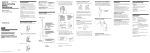
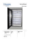
SERVICE MANUAL
COOKERS
Ovens
Compact Range
Microwave
© Electrolux Distriparts
Muggenhofer Straße 135
D-90429 Nürnberg
Germany
Fax +49 (0)911 323 1022
DGS-TDS-N
Edition:
08.05
Publ.-Nr.:
599 522 020
685
EN
Index
1.1
1.2
2.
2.1
2.2
2.2.1
2.2.2
2.3
2.3.1
2.3.2
2.4
2.4.1
2.4.2
2.4.3
3.
3.1
4.
4.1
4.2
4.2.1
4.2.2
4.3
4.4
4.5
4.6
4.7
4.8
5.
5.1
5.2
5.3
5.4
5.5
6.
6.1
6.2
6.3
7.
7.1
7.2
7.3
8.
Safety requirements .......................................................................................... 3
ESD=electrostatic discharge ............................................................................ 3
Software specifications, functions ..................................................................... 4
Panel example (Electrolux CH) ......................................................................... 4
Possible touch controls of all groups of appliances .......................................... 4
Microwave Combi .............................................................................................. 4
Microwave Solo ................................................................................................. 5
Symbol, explanation for display and keys .......................................................... 6
Display .............................................................................................................. 6
Function touch keys .......................................................................................... 7
Main features of operation ................................................................................. 8
Set clock ........................................................................................................... 8
Child-proof lock ................................................................................................. 8
Key beep ........................................................................................................... 8
Functions of appliance ...................................................................................... 9
Function of oven ................................................................................................ 9
Data of components / assembly situation / disassembly ................................ 10
Opening the appliance ..................................................................................... 10
View of open appliance .................................................................................... 12
Top view .......................................................................................................... 12
Rear view ........................................................................................................ 12
Disassembly of Kronos 2 input electronic ....................................................... 13
Disassembly of SOEC power board ............................................................... 15
Wave agitating motor / wave distribution ........................................................ 16
Magnetron........................................................................................................ 17
High-voltage transformer ................................................................................. 18
Access to the Ring-heatingelement ................................................................ 18
Technical equipment ....................................................................................... 20
Fan after-running ............................................................................................. 20
Measure against wrong electrical connection ................................................. 20
Safety cutoff of oven ........................................................................................ 20
Temperature safety device .............................................................................. 21
electronic safety system "Interlock" microswitch system ............................... 22
Fault diagnosis/ What to do if ...? .................................................................... 23
Fault codes ...................................................................................................... 23
Demo mode ON/OFF ...................................................................................... 23
Measuring the temperature sensor ................................................................. 24
Wiring diagrams / measuring points ............................................................... 25
Diagram microwave combi ............................................................................. 25
Diagram microwave solo ................................................................................ 26
Legend to the wiring diagrams ........................................................................ 27
Changes .......................................................................................................... 28
DGS-TDS-N 08.05 U. H. / A. B. © Electrolux
-2-
599 522 020
EN
1.1
Safety requirements
-
Before and during a repair you must take precautionary measures in order to
prevent that the service technician is possibly exposed to the microwave energy!
-
Never put the appliance into operation with open door!
-
Before putting an appliance to be repaired into operation, perform the previous
safety tests:
Locking behaviour of door - sealings and surfaces - hinges and bolts - mechanical
(foreign) interventions from the outside!
UNPLUG THE MAIN PLUG on measurements or repairs!
By all means discharge the high-voltage capacitor before. This must happen by suitable
lines with insulated spits!
With any microwave oven, a high-frequency leakage test (measurement of radiation
leakage) and the test according to VDE 0701 must be performed after a repair (this
includes also the opening of the appliance).
Microwave ovens may only be repaired by technicians who have been trained and
instructed correspondingly, who have the required tools, measurement devices and
technical documents!
Extensive information on the basis of microwave, measurement technique and
troubleshooting you can take from the Service Manual Microwave Ovens general, publ.
No.: 599 510 968.
1.2
ESD=electrostatic discharge
As the single electronic interfaces are not protected internally against statical electricity and are
partially open, you must pay attention to that, in case of a repair, there will be a potential
compensation via the housing of the appliance (touch it) in order to neutralize a possible
charging and to prevent a damaging of the affected electronic interface.
You also have to be careful with those electronics delivered as spare parts, which have to be put
out of the ESD protective package only after a potential compensation (discharge of possible
statical electricity).
If a potential compensation with an existing static electricity is not executed, it does not mean
that the electronic is demaged directly. Consequential damages may result due to the damaging
of internal structures which arise only in case of load through temperature and current.
Endangered are all assembly groups which are provided with control entries, wire paths lying
open and free-accessible processors.
DGS-TDS-N 08.05 U. H. / A. B. © Electrolux
-3-
599 522 020
EN
2.
Software specifications, functions
2.1
Panel example (Electrolux CH)
2.2
2.2.1
Possible touch controls of all groups of appliances
Microwave Combi
DGS-TDS-N 08.05 U. H. / A. B. © Electrolux
-4-
599 522 020
EN
2.2.2
Microwave Solo
DGS-TDS-N 08.05 U. H. / A. B. © Electrolux
-5-
599 522 020
EN
2.3
2.3.1
Symbol, explanation for display and keys
Display
2
3
4
1
5
6
13
11
8
10
7
9
12
symbol/indication no.
meaning/explanation
1
2
3
4
5
6
7
8
9
10
11
12
13
display baking/broiling programs and memory function
display microwave performance
thermometer symbol
duration
display weight
end
time of day
short time
display time of day
display temperature
display time of day
display oven functions
d=Demo-functions
DGS-TDS-N 08.05 U. H. / A. B. © Electrolux
-6-
599 522 020
EN
2.3.2
Function touch keys
Number of key 1-10
Depending on the appliance design it may be eight or ten touching keys. The functions of the
several keys are also different depending on the brand.
Microwave Combi
AEG
1
2
3
4
5
6
7
8
9
10
Start
To the bottom
To the top
Microwave
Programs
High speed heating
Minus
Plus
Clock Functions
Stop
AEG CH
Electrolux
Electrolux
EU/JUNO
Oven Functions
Programs
Memory Function
Memory Function
Light
Clock Functions
Minus
Plus
Reset
High speed heating
Microwave Solo
AEG
1
2
3
4
5
6
7
8
9
10
AEG CH
Electrolux
Start
Grill
Microwave
Programs
Minus
Plus
Clock Functions
Stop
DGS-TDS-N 08.05 U. H. / A. B. © Electrolux
Electrolux
EU/JUNO
Programs
Microwave
Clock Functions
Minus
Plus
Reset
-7-
599 522 020
EN
2.4
2.4.1
Main features of operation
Set clock
Information: The oven functions only with a set time.
When the appliance must be connected again with the mains e.g. after a repair, you have to set
the clock anew. Proceed as follows.
After the connection or a short circuit the symbol for „time of day“ is flashing. Use keys „+“ or „-“
to set the current time of day.
Wait 5 seconds
The flashing goes out and the clock shows the set time of day. The appliance is ready for
operation.
Note:
2.4.2
For detailed information on the operation/oven functions see
Service Manual 599 354 040
Child-proof lock
When the child-proof lock has been activated, the appliance can not be put into operation.
Activate child-proof lock
If necessary, switch off the appliance by the START key.
Press and hold "program" and "-" keys simultaneously until the display indicates "SAFE"
(approx. 2 seconds), until "SAFE" in the display goes out (approx. 2 seconds). Now the
child-proof lock is deactivated and the oven is ready for operation again.
2.4.3
Key beep
Deactivate key beep:
If necessary, switch off the appliance by the START key.
Press and hold "+" and "-" simultaneously until a beep will sound (approx. 2 seconds).
The key beep is now deactivated.
Activate key beep:
Beep sounds (approx. 2 seconds). The key beep is activated again.
DGS-TDS-N 08.05 U. H. / A. B. © Electrolux
-8-
599 522 020
EN
-9-
Min.
Grill heating element
Motor hot air
Ring-element
Microwave
Consumer
Motor wave agitator
Motor cooling magnetron
Coolingvan
Oven light
Oven sensor
ctive sensors/door switches Sensor magnetron
Door switch
Voltage cooling fan [%]
Microwave Solo
1500
26
1650
1750
4
30
19
26
Capacity [W]
TURBO GRILL
Drying
MW
250°C
180°C
30°C
1000W
250°C
250°C
250°C
100°C
1000W
30°C
30°C
X
30°C
X
X
30°C
100W
X
X
X
X
X
X
X
X
X
X
X
X
X
X
X
X
X
50
X
100
GRILL
X
100
X
100
DEFROST
X
X
X
X
X
X
X
X
100
MW
Suggested temperature
250°C
30°C
1000W
Max.
250°C
100°C
1000W
30°C
X
30°C
100W
599 522 020
Min.
Grill heating element
Motor hot air
Microwave
Consumer
Motor wave agitator
Motor cooling magnetron
Coolingvan
Oven light
Oven sensor
ctive sensors/door switches Sensor magnetron
Door switch
1500
26
1750
4
30
19
26
X
X
X
X
X
X
X
X
X
X
X
X
X
X
X
X
X
Functions of appliance
Max.
GRILL
3.
Suggested temperature
Hot air
Elux CH 170°C
Other 150°C
Function of oven
Capacity [W]
3.1
DGS-TDS-N 08.05 U. H. / A. B. © Electrolux
Microwave Combi
EN
4.
Data of components / assembly situation / disassembly
On principle the oven must be removed completely from the installation niche in case of service.
Note:
4.1
90% of all screws used in the appliance are Torx screws of size T20
Opening the appliance
The housing lid is made of a front and a rear half. For opening the front half of the lid you first
have to remove both Torx screws right and left.
User interface, power board, cooling fan, safety thermostat and door switch light are accessible.
DGS-TDS-N 08.05 U. H. / A. B. © Electrolux
- 10 -
599 522 020
EN
Housing screws
The rear upper half of the lid and the housing rear wall are one unit. For removing this unit
unscrew three housing screws each at the right and the left side of the appliance.
DGS-TDS-N 08.05 U. H. / A. B. © Electrolux
- 11 -
599 522 020
EN
4.2
4.2.1
View of open appliance
Top view
Türschalter
rechts
Eingabeelektronik
Kronos 2
SOEC
Powerboard
Türschalter
links
Motor Wellenrührer
Feinsicherung
Trafo Beleuchtung
Anschlüsse Grill
Sicherheitsthermostat (verdeckt vom Luftkanal). Mehr dazu Kapitel 5.4
4.2.2
Rear view
Motor Kühlgebläse
Transformator
Kondensator
Magnetron
Motor/Lüfterrad Kühlung
Magnetron
hot-air blower
Entstörkondensator
DGS-TDS-N 08.05 U. H. / A. B. © Electrolux
- 12 -
Connection
annular heating
element
599 522 020
EN
4.3
Disassembly of Kronos 2 input electronic
Fig.: Switch panel after disassembly
Fig.: Support springs switch panel
The switch panel is adjusted and attached by four springs to the panel support. For disassembly
you have to take off the switch panel from the panel support to the front.
Fig.: Touch board with data links
Fig.: Removed data link
Attention
At works the touch board is stuck directly onto the switch panel. Even in case of replacement,
the switch panel and the Touch board form one unit. It is provided with sensors which transmit
the received impulses to the user interface. This is realised via a data link. When disassembling
the switch panel pay attention to that both data links touch board/user interface have to be taken
off.
DGS-TDS-N 08.05 U. H. / A. B. © Electrolux
- 13 -
599 522 020
EN
Fig.:
Input electronic in installed condition and disassembling after unlocking
The input electronic is fixed by several locking hooks in the panel support. These must be
unlocked before it is possible to remove the input electronic to the front side of the appliance.
Locking hooks
DGS-TDS-N 08.05 U. H. / A. B. © Electrolux
- 14 -
599 522 020
EN
4.4
Disassembly of SOEC power board
Fig.: Assembly position SOEC power board
Fixing clips
It is positioned by five fixing clips. These must be released to remove the power board.
Note:
For technical description of the SOEC power board see Service Manual 599 354 040
DGS-TDS-N 08.05 U. H. / A. B. © Electrolux
- 15 -
599 522 020
EN
4.5
Wave agitating motor / wave distribution
The wave agitating motor is located in the center at the upper side of the appliance (see top view
of the appliance). It can now be removed by unscrewing both fixing screws right and left.
The task of the wave agitating motor is to impel the propeller-designed wave agitator made of
reflecting metal. As the wave agitator is continuously in another position, the reflection and the
wave distribution of the microwaves will also change continuously, which are guided to the oven
cavity through a metallic wave duct.
Wave agitating motor
Wave channel
Wave agitator
Wave agitator cover
DGS-TDS-N 08.05 U. H. / A. B. © Electrolux
- 16 -
599 522 020
EN
4.6
Magnetron
High-voltage transformer
Magnetron
The magnetron is the heart of the microwave. By means of the high-voltage transformer, the
rectifier and a magnetic field it changes the mains voltage of 230 Volt 50 Hz into microwave
energy with the frequency of 2450 Mhz.
Support screw nuts M5
The magnetron is kept to the wave duct with four screw nuts of M5 size. For removing the
magnetron you have to unscrew these.
DGS-TDS-N 08.05 U. H. / A. B. © Electrolux
- 17 -
599 522 020
EN
4.7
High-voltage transformer
The high-voltage transformer consists of three coils, a primary coil, a secondary high-voltage
coil and a secondary low-voltage coil. If the primary coil is supplied with 230V mains voltage,
following voltages are induced in the secondary coils:
-
3,1V
2750V
as low voltage directly to the heating coil of the magnetron
as high voltage
see also wiring diagrams Chapter 7
The transformer is installed at the rear side of the appliance. It is positioned to the support sheet
by two Torx screws. If these are removed, it is possible to take the transformer out of the
support at the lower side.
Holding screws
4.8
Fixture
Access to the Ring-heatingelement
Act as follows after removing the external sheet metal coverings (top/bottom):
1.
2.
3.
4.
5.
6.
7.
8.
Remove the wiring for the diverse connections and components and lay the cable
upwards.
Remove the high-voltage components: magnetron, capacitor, diodes and transformer (the
wire connections can remain (additional protection against an incorrect connection).
Remove the rear panel screws (4 items, see image 1).
Loosen the component plate (6 screws, 2 each at the side and bottom).
Allow the complete package to extend backwards.
Replace the defective component.
Reassemble in the reverse order.
Important: Do not squeeze the insulation when replacing the rear panel. The insulation
should seal well again. At the top, the cooling fan can be loosened and folded up so that
the insulation can be more easily positioned.
The ring-heatingelement can now be accessed.
DGS-TDS-N 08.05 U. H. / A. B. © Electrolux
- 18 -
599 522 020
EN
Fig. 1
DGS-TDS-N 08.05 U. H. / A. B. © Electrolux
- 19 -
599 522 020
EN
5.
Technical equipment
5.1
Fan after-running
After switching off the appliance the cooling fan continues running until the centre of gravity
temperature of the muffle has fallen below 140°C. In case of less than 140°C the cooling fan is
running approx. 10 minutes. The residual heat will be indicated until the temperature has fallen
down to 40°C.
5.2
Measure against wrong electrical connection
Not provided
5.3
Safety cutoff of oven
When setting function and temperature without a time limit, the safety cutoff of the oven
switches off automatically, depending on the set temperature.
DGS-TDS-N 08.05 U. H. / A. B. © Electrolux
- 20 -
599 522 020
EN
5.4
Temperature safety device
At the side of the air channel there is a double temperature safety device which will switch off all
poles of the appliance in case of overheating. The measured temperature value during a cutoff is
150°C.
Fig.: assembling location temperature safety device
DGS-TDS-N 08.05 U. H. / A. B. © Electrolux
- 21 -
599 522 020
EN
5.5
electronic safety system "Interlock" microswitch system
Opening the door activates all 3 microswitches via two mechanical systems. Primary and
secondary switch interrupt the power supply. If one of these switches does not open, the monitor
(surveillance) switch shorts the input circuit resp. the high-voltage transformer. In this
connection it is accepted that the microfuse will trigger off (see wiring diagram Chapter 7).
Monitor switch "Q1" and primary switch "Q2"
Installation location: behind the knob panel, left at the side
panel.
Actuating hook
Secondary switch "Q3"
Installation location: behind the knob panel, right at the
side panel.
Actuating hook
Microfuse "fuse" in the wiring diagram
Installation location: at the left side panel.
DGS-TDS-N 08.05 U. H. / A. B. © Electrolux
- 22 -
599 522 020
EN
6.
Fault diagnosis/ What to do if ...?
6.1
Fault codes
Display
E0020
E0101
Fault
oven lamp defect
Internal electronic problem
Cause/measure
Replace oven lamp
Execute mains reset.
Disconnect the appliance
from the mains and put it into
operation anew. If necessary,
substitute electronic.
check sensor and lines
If necessary, replace them.
E2020
No detection temperature
sensor.
Without contact or short
circuit.
Power board problem
E4040
Over-temperature
E0404
E0808
E0C0C
E4444
E4848
E4C4C
6.2
Execute mains reset.
Disconnect the appliance
from the mains and put it into
operation anew. If necessary,
substitute powerboard.
Replace stuck relay contacts
of radiators power board
Demo mode ON/OFF
Key combination:
Actuate „program“ and „+“ simultaneously 2 sec.
DGS-TDS-N 08.05 U. H. / A. B. © Electrolux
- 23 -
599 522 020
EN
6.3
Measuring the temperature sensor
If a failure at the temperature sensor is assumed, the resistance can be checked by means of
an ohmmeter.
The resistance of the temperature sensor should be 500 – 600 ohms at room temperature.
Make sure to measure the insulation resistance between the metallic housing and each
connection terminal.
The resistance should be higher than 2 MOhms.
Abb. Measuring the temperature sensor
DGS-TDS-N 08.05 U. H. / A. B. © Electrolux
- 24 -
599 522 020
EN
7.
Wiring diagrams / measuring points
7.1
Diagram microwave combi
DGS-TDS-N 08.05 U. H. / A. B. © Electrolux
- 25 -
599 522 020
EN
7.2
Diagram microwave solo
DGS-TDS-N 08.05 U. H. / A. B. © Electrolux
- 26 -
599 522 020
EN
7.3
Legend to the wiring diagrams
c2
Netzfilter
electronic board
Leistungsplatine
f1
f2
f7
fuse
Regler Temperatur Hauptbratofen
safety thermostat baking oven
Magnetronsensor
Feinsicherung
G5
Magnetron
h4.1
oven lamp
Q1
Q2
Q3
Monitorschalter Öffner links
Primärschalter Schließer links
Sekundärschalter Schließer rechts
m1
m2
m3
m5
m6
m8
fan hot-air blower
cooling fan broiling oven
Trafo Halogenlampe
Kühlgebläse Magnetron
Stirrer Motor
Hochspannungstransformator
r14
r16
grill
annular heating element
DGS-TDS-N 08.05 U. H. / A. B. © Electrolux
- 27 -
599 522 020
EN
8.
Date
Changes
Page changed
DGS-TDS-N 08.05 U. H. / A. B. © Electrolux
- 28 -
599 522 020
EN