1
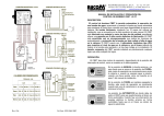
MR25 Service Manual
Radio modem designed
to transmit data
RACOM s. r. o.
Nové Město na Moravě
Czech Republic
May 23, 2005
Contents
Contents
Contents
1 Radio modem MR25
1.1 Description of functions . . . . . . . . . . . . . . . . . . . . . . . . . . . . . . . . . . .
1.1.1 MR25 Radio Part . . . . . . . . . . . . . . . . . . . . . . . . . . . . . . . . . . .
1.1.2 MR25 Modem Part . . . . . . . . . . . . . . . . . . . . . . . . . . . . . . . . . .
4
5
5
5
2 MORSE connectors
2.1 Antenna Connector . . . . . . . . .
2.2 MR25 Data Connectors – DSUB37F
2.2.1 Other pins . . . . . . . . . .
2.3 Wiring for RS232, V.24 . . . . . . .
2.3.1 RS232 interface . . . . . . .
2.3.2 V.24 interface . . . . . . . .
2.4 Service Connector Wiring . . . . .
2.5 MR25 Power Connector . . . . . .
2.6 Power connector types . . . . . . .
6
6
6
6
7
7
7
7
7
8
.
.
.
.
.
.
.
.
.
.
.
.
.
.
.
.
.
.
.
.
.
.
.
.
.
.
.
.
.
.
.
.
.
.
.
.
.
.
.
.
.
.
.
.
.
.
.
.
.
.
.
.
.
.
.
.
.
.
.
.
.
.
.
.
.
.
.
.
.
.
.
.
.
.
.
.
.
.
.
.
.
.
.
.
.
.
.
.
.
.
.
.
.
.
.
.
.
.
.
.
.
.
.
.
.
.
.
.
.
.
.
.
.
.
.
.
.
.
.
.
.
.
.
.
.
.
.
.
.
.
.
.
.
.
.
.
.
.
.
.
.
.
.
.
.
.
.
.
.
.
.
.
.
.
.
.
.
.
.
.
.
.
.
.
.
.
.
.
.
.
.
.
.
.
.
.
.
.
.
.
.
.
.
.
.
.
.
.
.
.
.
.
.
.
.
.
.
.
.
.
.
.
.
.
.
.
.
.
.
.
.
.
.
.
.
.
.
.
.
.
.
.
.
.
.
.
.
.
.
.
.
.
.
.
.
.
.
.
.
.
.
.
.
.
.
.
.
.
.
.
.
.
.
.
.
.
.
.
.
.
.
3 Radio modem MR25 versions
9
4 LED Numerals in the MR25
4.1 Seven-segmented display in the MR25 modem part . .
4.1.1 Condition while active connected terminal . . .
4.1.2 Condition without attached to service terminal
4.1.3 Writing into flash memory . . . . . . . . . . .
4.2 Seven-segmented display in the radio part MR25 . . .
.
.
.
.
.
.
.
.
.
.
.
.
.
.
.
.
.
.
.
.
.
.
.
.
.
.
.
.
.
.
.
.
.
.
.
.
.
.
.
.
.
.
.
.
.
.
.
.
.
.
.
.
.
.
.
.
.
.
.
.
.
.
.
.
.
.
.
.
.
.
.
.
.
.
.
.
.
.
.
.
.
.
.
.
.
.
.
.
.
.
.
.
.
.
.
10
10
10
10
11
11
5 MR25 Technical Specifications
12
6 MR25 Mechanical Specifications
13
Addresa:
RACOM s. r. o.
Mı́rová 1283
592 31 Nové Město na Moravě
esk Republika
Telefon:
+420 566 618 578
GSM +420 602 511 061
GSM +420 603 149 439
GSM +420 724 080 224
GSM +420 777 828 240
Fax: +420 566 618 035
email: [email protected]
www: www.racom.cz
c Racom s. r. o. – MR25 Service Manual
3
1. RADIO MODEM MR25
1 Radio modem MR25
The MR25 is a radio modem designed to transmit data in the VHF and UHF bands with 25 kHz (12,5 kHz)
channel spacing. The radio modem uses 4-level GMSK modulation which makes possible a maximum
communication speed of 21.68 kbps (25kHz channel spacing). From the point of view of the data network’s
architecture, it is possible to consider the radio modem as an autonomous system; the operator has at his
disposal three standard ports RS232 (it can by converted to RS422/485 by RACOM optocouplers OPI).
Identification of modems by frequency band
• 146 – 162,2 MHz – RACOM160S21L
• 162,2 – 180 MHz – RACOM160S21H
• 300 – 360 MHz – RACOM300S21
• 400 – 444 MHz – RACOM400S21L
• 444 – 493 MHz – RACOM400S21H
By means of the modem module, it is possible for the radio data transceiver to configure an arbitrary
transmission and receiving frequency in the divided frequency span 3.2 MHz in the 25 kHz or 12.5 kHz
channel grid. Input and output work frequencies are independent of each other and are derived from the
frequency by the 4-phase lock-loop system programmed in the transceiver microcontroller. The channel
setting is stored in EEPROM memory in the transceiver and in FLASH memory in the modem module,
whose communication processor controls the performance of the transceiver microcontroller. The output
power of the high frequency signal from the radio modem transmitter is digitally adjusted in 16-steps.
A description of the MR25 software controls and configuration is available in the publication Morse
Firmware – Documentation in the chapter Morse main menu.
4
c Racom s. r. o. – MR25 Service Manual
1. RADIO MODEM MR25
1.1
1.1.1
1.1. Description of functions
Description of functions
MR25 Radio Part
The architecture of the MR25 radio modem provides for a comfortable and reliable working station. Frequency synthesis makes possible multi-channel operation, with the synthesizer’s dividing conditions being
stored in EEPROM memory. The performance of the radio data transceiver module is controlled and diagnosed with the microcontroller.
The logic circuits, the switching stations between the receiving and transmitting modes, have high
signal noise immunity and activate the relevant blocks gradually. This minimizes most of the transient
parasitical conditions, and optimizes the bandwidth when switching over.
The receiver part of the modem works with two mixes. Centralized selectivity is divided between both
interfrequency degrees. The first filter maintains the basic channel preselection until suppressed, ensuring
linear functioning for the second mixer and the interfrequency amplifier. The second filter has suppression
characteristics needed for channel selection in the 25kHz user’s channel space.
1.1.2
MR25 Modem Part
The modem part is composed of three basic blocks:
1. the microcomputer controller
2. the convertor circuits for standards RS232
3. the modem data circuits.
The microcomputer has 512 kB of flash memory and 64 kB RAM memory available. Included among
the circuits are a backup battery for power in real time, a detector for monitoring lost power, and a circuit
watchdog.
During a power failure, a charge preserved in the electrolytic capacitor enables the exact time of the
occurance to be recorded into flash memory. So, the operator has the relevant information on-hand to
determine the length, extent, and manner of the blackout.
The microprocessor activity is protected by a circuit watchdog. Protection is implemented by the
processor chip and if needed, it carries out a 16 second reset.
Convertors RS232 can work with speed limitation 120 kbps. The convertors are protected against
prestress by TRANSIL components.
Data conversion on the 4-level FSK modulation signal and back is made possible by a specially programmed circuit made by CML. The transmission speed of 21680 bps is derived from the crystal oscillator
on the board of the radio part.
c Racom s. r. o. – MR25 Service Manual
5
2. MORSE CONNECTORS
2 MORSE connectors
2.1
Antenna Connector
The cable for connecting the antenna is equipped with a MINI UHF type connector. The fitting for the
connector corresponds to the type and impedance. For antenna leads, we recommend cable RG58 for
lengths up to 10 m, and RG213 for longer lengths.
2.2
MR25 Data Connectors – DSUB37F
All inputs/outputs, three serial ports, and some parameters for service functions run through this connector.
Signals shown in the table are functions depending on the version of the MR25 (more in the chapter 3).
The old designation COM 1, 2, 3 is replaced by SCC 0, 1, 2 now.
Port SCC0
pin
2
21
4
1
in / out
RxD
RTS
DTR
CD
pin
3
22
20
23
Port SCC1
in / out
TxD
CTS
DSR
GND
pin
27
9
29
26
in / out
RxD
RTS
DTR
CD
pin
28
10
8
11
in / out
TxD
CTS
DSR
GND
Port SCC2
pin
32
14
13
2.2.1
pin no.
pin no.
pin no.
pin no.
pin no.
pin no.
6
in / out
RxD
RTS
CD
pin
33
15
34
in / out
TxD
CTS
GND
Other pins
17
36
37
7
31
19
(ExtPTT)
(Ext AF)
(GND)
(-10V)
(-10V)
(+12V)
– input/output for station service transmission
– audio frequency output for demodulator
– ground
– auxiliary signal for SCC0
– auxiliary signal for SCC1
– this input is not for direct supplying of external devices! The using
consult with producer.
c Racom s. r. o. – MR25 Service Manual
2. MORSE CONNECTORS
2.3
2.3. Wiring for RS232, V.24
Standard Connector Wiring for Interfaces RS232, V.24,
DCE equipment
2.3.1
RS232 interface
. Cannon DSUB9F connector
pin
1
2
3
2.3.2
signif.
CD
RxD
TxD
pin
4
5
6
signif.
DTR
GND
DSR
pin
7
8
9
signif.
RTS
CTS
—
pin
11
12
13
14
15
signif.
—
—
—
—
TxC
V.24 interface
. Cannon DSUB25F connector
pin
1
2
3
4
5
2.4
signif.
—
TxD
RxD
RTS
CTS
pin
6
7
8
9
10
signif.
DSR
GND
CD
—
—
pin
16
17
18
19
20
signif.
—
RxC
LAL
—
DTR
pin
21
22
23
24
25
signif.
RDL
—
—
—
TI
Service Connector Wiring
Designated Service Cable DKR12. The wiring of DSUB9 connector corresponds to DTE devices.
GND
2.5
Cannon DSUB9F
pin 5
RX data
pin 2
TX data
pin 3
MR25 Power Connector
GND
+13.8 V
Figure 2.1: The wiring of power supply plug in MR25
c Racom s. r. o. – MR25 Service Manual
7
2.6. Power connector types
2.6
2. MORSE CONNECTORS
Power connector types
The type of power cord used is NKRx.
8
c Racom s. r. o. – MR25 Service Manual
3. RADIO MODEM MR25 VERSIONS
3 Radio modem MR25 versions
The following chart shows the port asignement to individual versions of the MR25:
MR25 type
MR25X ver.≤11
rzn subverze
MR25X ver. 12
MR25ET
MCM302ET
RS232 simple
RS232
V.24
TxD, RxD, RTS,
CTS, DSR
TxD, RxD, RTS,
CTS, DSR, CD
TxD, RxD, RTS,
CTS, DSR, CD,
TxC, RxC
?
RJ45 Ethernet
?
?
?
?
?
?
?
?
• MR25X hw version 11 and older was produced in more subversions labeled:
◦ XS – with synchronous port V.24
◦ X4 – ports configurable to RS485, RS422
◦ XE – economy, with limited volume bytes/min
◦ X – asynchronous port RS232 or RS232 simple which covers the majority of cases
• MR25X hw version 12 produced since 8/2001 has the RS232 port only
• MR25ET is equipped by synchronous port V.24 in context with faster medium Ethernet
• RS485 or RS422 signals can be connected by optocouplers OPI485 or OPI422
• The DSR signal is connected via resistence to +12V
c Racom s. r. o. – MR25 Service Manual
9
4. LED NUMERALS IN THE MR25
4 LED Numerals in the MR25
4.1
Seven-segmented display in the MR25 modem part
Located on upper part of MR25, near of the RACOM logo.
DQ (20−31)
DQ − Data Quality
DQ
(12−19)
DQ
(6−11)
The received packet is for this modem
(for any adress of the modem)
Flashing:
request state, read the error logs
Sync
DQ (1−5)
Continuos light:
service state
TX on
Sync: synchronization of modem circuits
TX on: illuminates when giving a command
for transmission
4.1.1
Condition while active connected terminal
Condition while switching on the modem, a connector from an active connected terminal is inserted in the
service connector:
• b indicated – the base loader module is launched, if Enter is pressed within the next 3
seconds, the modem stays in this module
• after quick changing a pair of characters the display remains dark for next 6 seconds -/- the
main module is launched. If any ordered command is send from Setr on this time, then the
whole menu goes to the default values in memory. If it doesn’t happen, the program starts
with the values set in flash memory.
• after finishing the start process a group of number leaded by letter r or c starts circulate. This
number indicates the version of software.
Modem is set in MORSE mode
• Modem is set in C92 mode
4.1.2 Condition without attached to service terminal
Condition while turning on the modem, the service connector is not attached to any active connected
terminal:
10
c Racom s. r. o. – MR25 Service Manual
4. LED NUMERALS IN THE MR25
4.2. Seven-segmented display in the radio part MR25
• after quick changing a pair of characters the display remains dark for next 6 seconds – the main
module is launched.
• after finishing the start process a group of number indicating the version of software starts circulate.
From the previous information, it can be gathered that the ideal conditions (high DQ, packet received
for this modem, modem circuits synchronized, etc.) are indicated by a 0 (zero) when receiving.
Error states:
• Center segment flashing – check and analyze the error logs.
• Zero is not indicated – relatively low DQ, the modem did not synchronize or the packet is not destined
for this modem
• Sync is not indicated – the modem is not able to synchronize with any packets on the RF channel.
Sync should be indicated for the duration of receiving.
• Nothing is indicated – some unknown operation for the modem is on the RF channel, eg. packets are
transmitted with another polarity (menu FMe), there is interference on the RF channel.
4.1.3 Writing into flash memory
When writing into flash memory by the service terminal SETR (commands w – write and I – Init) the
display signalize shortly:
4.2
Seven-segmented display in the radio part MR25
Located near of the antena connector.
−70 to −80 dBm
−80 to −90
dBm
S−metr
−60 to −70
dBm
−90 to −100
dBm
> −60 dBm
−100 to −110 dBm
TX
TX on: illuminates during transmission
If the station is in a quiet state, a cyclical letter notice rid 3o2 is displayed, or if need be another
number of the software version.
While receiving, the station evaluates the signal level (S-meter). If the level is less than 110 dBm, the
notice rid 3o2 appears. The maximum level is indicated by 0 (zero).
When Error message is running on the display, it is a grand error condition, when at least one PLL in
station is not locked.
c Racom s. r. o. – MR25 Service Manual
11
5. MR25 TECHNICAL SPECIFICATIONS
5 MR25 Technical Specifications
Frequency ranges
Channel spacing
Number of channels in working band
Method of setting up working frequency
Switching time transmit / receive
Temp. range for guaranteed parameters:
Temp. range for guaranteed functionality:
Atmospheric pressure
Relative humidity
Supply voltage
Current consumption
transmission 1W
max. output
Dimensions MR25 only
Dimensions MR25 with heat sink and holders
Dimensions MR25ET with heat sink and holders
Weight MR25 only
Weight MR25 with heat sink and holders
Weight MR25ET with heat sink and holders
Antenna connector
Receiver sensitivity for BER 10−3
Frequency stability
Receiver intermodulation response
Adjacent channel sensitivity 12.5 kHz
Adjacent channel sensitivity 25.0 kHz
Spurious response rejection
Spurious receiver radiations
Receiver spurious response rejection
Receiver desensitisation
Transmitter power
Transmitter output impedance
Spurious transmitter emissions
Transmitter power in adjacent channels 12.5 kHz
Transmitter power in adjacent channels 25.0 kHz
Max. modulation transmission speed 12.5 kHz
Max. modulation transmission speed 25.0 kHz
Standard interfaces in modem part
Max. speed on user channels
Memory
Software diagnostics through the network:
• measuring receiver signal strength
• adjusting output power
• monitoring
Remote config. possibilities: all necessary parameters
Software modification through the network
12
146 – 162,2, 162,2 – 180 MHz
300 – 360 MHz
400 – 444, 444 – 493 MHz
25 kHz (12.5 kHz)
128 (256)
software
< 2 ms
−25 to +55 ◦ C
−30 to +55 ◦ C
700 – 1200 hPa
10 – 90 %
13.8 V
0.5 A
1.1 A
2.0 A
84×190×52 mm
84×190×71 mm
84×190×97 mm
890 g
1 150 g
1 360 g
mini UHF
better than −107 dBm
according to ETS300113
> 70 dB
60dB
70dB
> 70 dB
< 2 nW
> 70 dB
84 dB
0.1 – 5 W
50 Ω
< −36 dBm
< 60 dBc
< 70 dBc
10.84 kbps
21.68 kbps
3× V.24 (without synchronization)
115 Kbps async.
64 kB SRAM
512 kB FLASH EEPROM
yes
yes
yes
yes
yes
c Racom s. r. o. – MR25 Service Manual
6. MR25 MECHANICAL SPECIFICATIONS
6 MR25 Mechanical Specifications
R
REAR FACE
FRONT FACE
66.5
P
84
P2
P
69.7
R
M3
200
210
PANEL
HOLDER
SCREW
13.5
188
205.5
MR25
c Racom s. r. o. – MR25 Service Manual
400MHz
13