1
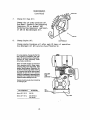
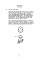
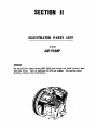
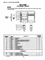
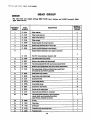
WWW.LONDONFOGGERS. COM
EMAIL: SALESSUPPORT @ LONDONFOGGERS. COM
ULTRA LOW VOLUME
AEROSOL GENERATOR
O e
OPERATION
MAINTENANCE
AND
PARTS
Pending
CUSTOMER SERVICE-A TRADITION
505 Brimhall Ave PO Box 406
PHONE: (800)448-8525
Long Lake, Minnesota 55356
FAX: (952) 473-5302
INDEX
Forward
1
2
3
5
8
9
10
11
11
11
13
14
15
16
16
18
19
20
Specifications
Safety Precautions
Assembl y/i nsta I I a t .ion
Servic Before start-Up
Pre-start Check List
Start-Up
Operation
Setting Flow
Rate
Calibration
Spraying
Flushing
Service Schedule
Ma i ntenan ce
Air Presur, e
Air Pump
Belts
Engine Oil
NOzzle
3)
Flushing
Air Pump
Oil
Formulation Filter
Air Pump Fi I ters
Engine Air Cleaner
Battery
Spark Plugs
Engine Carbon
Engine Cool ing
Engine Crankcase Breather
continued
21
22
22
23
23
"24
INDEX
(continued)
Maintenance' (continued)
Governor
Pulsation Tank
Pul sation Damper
Over Pressure Switch
Trouble Shooting
Preparation
for
Schematic Fluid
Storage
System
Wiring Diagram,
Wiring Diagram,
Cab Control
Machine
Illustrated Parts
Basic Machine
Air Pump
.J .anuary 1986
FOREWARD
The application of insecticides is the predominant method
by which man attempts to limit the size of insect populations.
Due to economic as well as environmental reasons, it is desirable to treat a given area with the least amount of insecticide
that can be made to be effective. The most efficient method is
to break up the liquids into aerosols and distribute these fine
droplets over the affected area. The fine particles stay suspended for longer periods of time due their size and are
distributed more evenly, remaining effective longer.
The term U.L.V. is an.abbreviation for the terms Ultra Low
Volume. Ultra Low Volume is the designatio.n of the technique
of treating areas with relatively small amounts of chemicals in
the. aerosol state. These chemicals are usually in a more concentrated state than chemicBls used in other methods of
appl i cation.
For best results, London Aire ULV Aerosol Generator should
be operated and maintained in compliance with the formulation
label instructions.
.DESCR.'. ION
This machine is intended to be vehicle or trailer mounted
and is designed to be operated by. the driver of the vehicle"iith
the remote control box.
SPECIFICATIONS
TYPE"
Vehicle or trailer mountable non-thermal,
U.L.V. (Ultra Low Volume) Cold. fog aerosol
generator.
ENGINE-
Kohler .M.clnxn.cast iron, one. cylinder, 4-cycle, gasoline,
8. h.p., 12v Fuel Consumption regular Or no lead
automotive 0.7 .gal/hr.. (2.65
electric
start with alternator.
AIR PUMP"
Positive displacement, 4 cylinder, all cast iron,
belt driven, 900 r.p.m.
FORMULATION PUMP"
iter/hr)
displacementpiston pu.mp
with adjustable
oz./min. (0 to 295.7 ml/min.)
360 horizontal adjustment (azimuth) and 30-60
vertical adjustment (elevation).
Positive
output from: 0
NOZZLE SYSTEMTANKS"
to 10
.corr.osion-resistant, high density po.ly.ethylene, .( fb-cmu l at i on and flushing tanks onlly).
Formulation- 15 U.S. Gallons (56.7 Liters)
Flushing" .1.5-U.S. Gallons (5.67 Liters).(Optionl)
All tanks
(11.3 Liters)
(mass median diameter)
Gasoline" 3.0U.S. Gallons
PARTICLE SIZE-
5 to 20 Microns MMD
on flow rate and
depending
LENGTH"
pounds (127 kilograms)
42 inches (106 cm)
WIDTH:
34
HEIGHT"
30
WEIGHT EMP.TY
280
inches (86 cm)
inches (76 cm)
v.i-scosity.
I. SAFETY PRECAUTIONS
WARNING
READ AND UNDERSTAND THESE SAFETY PRECAUTIONS BEFORE OPERATING
MACHINE.
1.
uses gasoline as. the fuel for the
precautions commonly applying
all
int.ernal .combustion engine and
Exercise extreme caution
observed..
to this volatile fuel should be
of
spillage
gasol.ine.
If
to avoid spilling
occurs, wipe it off and
engine.
DO NOT attempt
the
time
starting
allow evaporation
before
running.
Avoid
still
machine
the
is
tank
while
to put fuel in the
smoking or open flame .in area when handling gasoline. Never run the
unit indoors unless exhaust is vented to outside. These fumes
contain carbon monoxide which is colorless and odorless and can be
fatal.
ENGINE AND FUEL: This mchine
NOTE
DO NOT OPERATE ENGINE WITHOUT MUFFLER.
DO NOT TOUCH HOT MUFFLER, CYLINDERS OR FINS
AS CONTACT MAY CUSE BURNS.
Except for adjustment DO NOT OPERATE THE ENGINE
IF AIR CLEANER OR COVER DIRECTLY OVER THE CARBUETOR
AIR INTAKE IS REMOVED.
DO NOT RUN
THE
UNIT IF THE BELT GUARD IS REMOVED.
DO NOT TAMPER wITH.GOVERNOR SPRII(GS,. GOVERNOR LINKS
OR OTHER PARTS WHICH MAY INCREASE OR DECREASE THE
GOVERNED ENGINE SPEED.
-2.
TheENGINESPEED (RPM) should be check periodically to ensure that
it iS o'er'a'ting" orrectly, as the engine affects the air pressur.e...
and formulation flow which.affects droplet size. The correct
engine speed should be 2700rp.m. plus or minus 150r-pm.
3. 'MACINEDAMAGE.
Never
A-damaged machine can
4. 'WIND:
Operate
a machine after it has been
hazardous.
be very
Spraying during windy conditions
is
damaged.
not.usually practical
-beCause .the formulation will drift out of the intended area.
However, underNO circumstances should spraying into the wind be
attempted. This may cause hazardous accumulations of formulation
on the machine orcarrying vehicle.
SAFETY PRECAUTIONS
(continued)
5
EQUIPMENT: In addition to any safety equipment thal- may
the type of formulation which is being used', the
following items should be with each vehicle which carries this
machine during fogging operations"
a. Fire Extinguisher, chemical type rated for fuel fires.
SAFE,TY
be'
reqdirel by
First Aid Kit.
c. Eye Wash Solution.
d. Safety Glasses
e. Container of Oil Dry Compound
f. Gloves rated for high temperature.
g. Respirator adequate for formulation
b.
6.
7.
being used.
'CHILDREN- Many spraying operations are performed in residential
areas conlnonly at dusk. This presents the operator with the
problem of. children who are attracted to the noise and/or the
mist being created. The possible hazard l is in the toxic effect
of some formulations, the severity of which depends upon the
chemical used, mist density, and the length of time of direct
exposure. IT IS THE OPERATOR'S RESPONSIBILITY TO DISCOURAGE ANYONE FROM PLAYING IN THE MIST OR BEING NEAR THE MOVING VEHICLE.
FORMI)ILATIONS- Ensure that formulations are applied only in strict
om-p)iance with the formulation label as well as local, state, and
federal regulations and that these formulations are dispersed only
by trained personnel of public health organizations, mosquito abatement districts, pest control operators or other qualified personnel.
a. Always comply with any requirements for protective clothing.,
goggles, gloves, facial masks, or respirators required on
the formulation label.
b. Do not exceed the dosage set forth on the regist.ration
label of the insecticide to be used.
Always
store formulation in its original labeled container.
.c.
IN NO WAY IS IT TO BE CONSTRUED THAT THE CHEMICALS AND/OR DOSAGES ARE THE
RECOMMENDATION OF LONDON FOG, INC.
LONDON FOG, INC. SHALL IN NO EVENT BE LIABLE FOR CONSEQUENTIAL DAMAGES OR
CONTINGENT LIABILITIES ARISI.NG OUT OF THE .FAILURE OF ANY AEROSOL GENERATOR
OR PART TO OPERATE PROPERLY.
I I.
1.
ASSEMBLY/INSTALLATION INSTRUCTIONS
Uncrate the unit and
remove
all
packing materials.
NOTE
2.
3.
It is a good idea to retain the original machine
shipping carton as well as its inner packing and
blocking materials for any future storage and/or
shipment which may be required.
Place the Remote Control Unit where it will not be damaged
while machine is being prepared.
Lift the machine onto the vehicle with the discharge end of
machine toward the
rear
the
of the vehicle.
4.
Pass the Remote control unit through an open window and locate
within reach of the person who-wil] be operating the machine.
If permanent vehicle installation is desired, the remote control
cable can be passed through a small hole in the vehicle cab and
then reconnected. Make sure the small hole provides proper
protection against wiring damage and is re-sealed to prevent
exhaust gases from entering inside of the vehicle.
5.
Using the most convenient routing, run the conlrol harness to the
connecting support bracket.located on the engine gas tank bracket.
Orient the electrical plug on the harness so that the electrical
pin locations match the mating pin receptacles in the socket and
push the plug firmly into the socket.
Push the air line connector into the mati.ng quick connect socket
and lock into place.
Securely bolt the machine to the vehicle.
Correct battery type is Group U1 garden tractor. Use NAPA 8221,
Sears 9603 or any equYa!-en.t--measuri.ng 7 3/4. x 5 1./4 x 7 1./4-high.
6.
7.
WARNING
DANGER
POI SON
BKrTERIES PRONC.EXPt.OSIVEGASES. KEEP SPARKS, FLAMI, CIGARETI'ES, AWAY.VENTILATE WHEN CHARGING OR USING IN AN ENCLOSED SPACE.
BAIIERIES CONTAINStlt.FURICACID WHICH CAUSES SEVERE BURNS. IF ACID CONTACTS
EYES, SKIN, OR CLOTHING, F'L'USH WELL WITH WATER. FOR CONTACT WITH EYES, GET
INEDIATE MEDICAL TTENTION.
KEEP
BATTERY AND ACID AWAY FROM CHILDREN AND OTHER P,ERSONS WHO MAY NOT BE
AWARE OF DANGERS INVOLVED.
ASSEMBLY/INSTALLATION. INSTRUCTIONS
(continued)
A.
Remove
batter
mounting
from. its
and
place
workbench.
on a
stable
B.
Remove vent caps from battery. Remove or destroy any sealing
device which may have been used to close or restrict the vent
opening in the caps.
C.
Fill each cell of the battery to the top of the separators
approved battery electrolyte of 1.265 specific gravity.
with
NOTE
Temperature of battery and electrolyte at the time f filling
should be above 60 degreesF. (i5 degreesC.)
CAUTI ON
Never fill battery in machine as spills will
on frame and cause-premature corrosion.
D.
damage
finish
12 volt battery at 30-40 amps until the acid temperature
is above 80 degrees-F. (26 degrees-C.) and the hydrometer reading
is 1250 or higher.
Charge
NOTE
Both temperature and
hydrometer readi.ng requirements
must be
met.
E.
After cha.rgi.ng the battery, check acid l evel in all cells and
fill each cell withacid to the proper level.
.F.
Re-install vented caps.
.G.
Re-install the battery onto machine.
Ho
Connect Positive (+) cable (leading from the starter switch which
i s located on the e.ngi ne switch panel) to the positive (+) post
on the battery and tighten bolt.
I.
Connect the
battery and
Negative (-)
tighten bolt.
cable to the
Negative (.-) post
on
the
AS S E_MBL Y/I N STALL AT I ON I N STRUCT IONS
(continued)
CAUTION
installing battery,
negative
sparking anl shorting.
required, remove negative
a.
When
(-)
cable last to prevent
b.
When
disconnecting is
connection first.-
c.
Reversed polarity can
and charging systems.
(-)
connect the
cause
damage
to the
starting
NOTE
After battery has been initially serviced, only water
should be added to restore the liquid level in each cell.
Further addition of acid will cause battery failure.
8.
Loosen the ball swival joint and.orient the nozzle as required hy
the formulation label. Usual set-up is towards the rear and 45
up. Retighten ball joint.
III. SERVICE.BEFORE START-UP1.
2.
Engine- Servie engine with gasoline and oil as per the
accompanyingEngine Operating and Maintenance Instructions.
(Engi.'ne may already be serviced with oil.)
Air Pump: Before starting, the machine, remove the dipstick and
heckoil level. Fill as necessary with SAE 30 nn-dtergent type
oil for the first 50 hours of operation. Oil level should never
be higher than the upper mark on the dipstick, nor lower than the
lower mark.
After the 50 hour break in period, the compressor oil should be
changed to a synthetic oil such as Anderol 500 or Amsoil Synthetic
Reciprocating Compressor oil available locally or from London Fog Inc.
(part number 2319, pint or part number 2320, quart)
NOTE
synthetic type oil is recommended due to the lower maintenance
requirements for the air pump and other components. DO NOT mix
The
oils.
3. 'Drive-belts- Check drive belts which should be in
l-i gnment and tight.
perfect
IV. PRE-START CHECKLIST
1.
Verify
the
2.
that the remote control box is within easy reach of
operator.
Verify that the nozzle is in the correct position as required
spraying operation to be accomplished, and that the
ball joint which allows this positioning is tight.
Verify that the engine has sufficient fuel and is properly
for the
3.
Iubricated.
4.
5.
6.
Verify that the air pump has been serviced.
Inspect all hoses for abnormal conditions.
Verify that no foreign objects or tools have
been left in
or
about the machine.
7.
8.
9.
Verify that sufficient amount of formulation is in the tank and
that the tank filling plug is tight, and that the air vent hole
(located on the underside of the tank handle) is not obstructed.
Verify that the battery is mounted securely and cable connections
are proper and tight.
Verify that all safety equipment is in place and is in proper
working order.
CAUTI ON
Before proceeding with any spraying operation, the operator should
be thoroughly famil.iar with starti.ng and stopping the machine and
with all the operating controls. If you are operating the machine
for the first time, exercise the machine through its full operational
sequences from a position of full visibility of the machine before
operating the machine fully remote. This is also a good idea for
experienced operators who may be operating a new machine or who may
be reactivating a machine after repairs or a period of inactivity.
Refer to the operation sect:i.on for starting and stopping instructions.
V.
START UP
NOTE
On machines equipped with remote start, the engine may be started from
either the engine or the remote control box. When cold, choking may be
required on the initial start-up.
Verify that the spray On-Off switch on the remote control box is in the OFF
position.
Place the Ignition On-Off switch on the remote control box into the oN
stion and the ignition key on engine t the "ON" position.
The engine may now be started from either the remote control box with
the START swtch or from the engine by turning e key t e start
position.
NOTE
The best starter life is provided by using short cranking cycles of several
seconds: prolonged cranking can damage the starter motor if cranked
more than 15 seconds per minute.
CAUTION
On each start up, be sure the formulation pump does not run dry. If there
is no formulation in the lines, immediately turn on the spray nozzle so that
formulation is drawn through the system. The spray may be turned off as
soon as formulation reaches the nozzle.
10
Vl.
OPERATION
Read this complete OPERATION section and the section on SAFETY
PRECAUTIONS before taring the machine.
For first time operation the sections on INSTALLATION, SERVICE BEFORE
STARTUP, and PRESTART CHECKUST must be performed before proceeding
with operation.
When operating this machine for the first time, move to an uncongested and
well ventilated work area in open rea away from flammable materials.
WARNING
READ THE SECTION ON SAFETY PRECAUTIONS BEFORE
PREPARING TO DISPENSE FORMULATION.
RED AND THOROUGHLY UNDERSTAND ALL INFORMATION,
CAUTIONS AND WARNINGS ON THE FORMULATION LABEL WHICH
IVlAY AFFECT PERSONAL SAFETY. KNOW ANY DANGERS OF THE
SOLUTION USED AND KNOW WHAT TO DO IN CASE OF AN
ACCIDENT INVOLVING THE SOLUTION.
ALWAYS USE THE APPROPRIATE SAFETY EQUIPMENT AND DRESS
ACCORDING TO THE CHEMICAL FORMULATION WHICH IS BEING
USED.
DO NOT USE ANY SUBSTANCES FROM. UNMARKED CONTAINERS
OR FROM CONTAINERS WITH OBVIOUSLY ALTERED LABELS.
READ AND FOLLOW THE INSTRUCTIONS ON THE CHEMICAL
SOLUTION LABEL FOR ULV SPRAYING OF THE SOLUTION.
DO NOT SPRAY NEAR AN OPEN FLAME OR HOT MATERIALS.
DO NOT LEAVE THE MACHINE UNATTENDED.
1. CAUBRATION: SETTING THE FLOW RATE
.C.A.UTION
Before calibration, be sure the machine fluid lines are free from any air
bubbles. Ort initial start-up, it may be helpful to temporarily move the
pump pointer to a high scale reading to get the system pdmed and the
lines purged of any air bubbles.
11
OPERATION
(continued)
'SPRAYING
CAUTION
Before dispensing insecticide, be certain that no one is present in the
area of the nozzle or aerosol dispersion area.
To dispense insecticide with the ULV machine running, move the
flow control on/off nozzle switch (cab control) to the ON position.
The green indicator light should come on.
The air pressure gauge on the cab control panel should read
between 75 and 85 pound per square inch pressure. If this
pressure is not present, shut off the flow control switch and see Air
Pressure Instructions. DO NOT dispense insecticide until the air
pressure problem is corrected.
OPERATION
(continued)
The fluid pump system is calrated to the graduated scale on the pump
at the London Fog factory, ff any major deviation in the flow rate occum,
first check the other components in the system (such as strainers, dtings,
etc.). Check tr air bubbl in e son side t e ne 11 e
pressure side. Check for tluid leaks in the pressure side of the lines.
Minor deviations not created by equipment malfunctions, should they
occur, may be recalibrated by measuring the flow and adjusting the
pump mering pointer unll e desired flow obined.
Td measure the flow, disconnect the fluid line from the aerosol nozzle.
Pice e dconneetcl line into an empt ntainer.
Start the pump. Wdh the cab panel flow control switch turned on, fluid
will pumped rough e disnneed line iro he rNner. Move
the disconnected line from the container to a measuring beaker for a
measured arrunt t me I'eferab using a Nop watch.
Compare the measurPamount to the flow desired or to the pump scale.
Adjust or lock the pump pointer as may be required.
Be sure to replace all lines and fittings after calibrating.
The following are rough estimates of flow rates using very light mineral oil.
Alwa_vs r,librte to establish correct.flow ..etes for the chemical or insecticide to
be used.
Flow R.pte (mllne_l
95
150
25O
320
410
475
Flow Rate (oz./minute1
3
5
8.40
10
14.20
16
13
Scale. Settinq
.50
1.00
1.50
2.00
2.50
3.00
OPERATION
(continued)
FINISHED
OpERATION
When the spraying operation is complete, the unit must be flushed
in accordance with "FLUSHING SYSTEM" section of this manual.
4.
FLUSHING
A
StorageWhen flushing for storage, drain the formulation tank and
place flushing fluid in the main formulation tank. Run
the generator with the nozzle solenoid valve in both the
ON and OFF positions to clean all lines. Drain any remaining flushing solution from.formulation tank. Repeat
Before
as
Bo
necessary.
After each.use
1.
2.
(without
Built-In Flusher
With the aerosol generator
nozzle.
running,
accessory)turn ON the spray
At the formulation filter (large white nylon assembly),
disconnect the larger (3/8") fluid line which runs-from
the filter to the Posi-Drive pump. Place this line in
"a container of flushing solution. Run the unit until
the flushing fluid has cleaned the lines, pump and
nozzle.
NOTE
More
pump
rapid flushi.ng may be accomplished by moving the
pointer to a high flow rate. setti.ng.
CAIJTION
flushing the generator, the sproychMUST be turned ON (at the cab
control) so that the mach----"ne is discharging aerosol.
When
3.
CQ
Reconnect the fluid line to the formulation filter.
Tighten very finger tigh t Do not use wrenches.
After each
use
(with
Built-In
Flusher)-
Use same method as B above except in step #2, just turn the
flush valve to the F-LUSH position. Eliminate step #3 above.
i4
VI I. SERVICE SCHEDULE
_Daily
ITEM TO BE SERVICED
ltozzle /i r 'lesure
Interval
25
,so,
l,,Soo
X
X
X
X
X
Calibration
Check.Al r Pump Oi I
.heck, Air P,u.p. Belts
Check Engine 0ii
Cl ean Nozzle
Flush
Change Air Pump Oi 1
X
Change En.gine 0.!1_,
Clean Formulation Filter
..Cle..an Air. Pump_Air F.i!t,ers
Replace Engine Air Clean,er_E1ement
Check Batter
X
X
Cck/Gap .Sark PIu_g
.D.ecarbo.n i ze E.ngi ne
X
Service Breaker-Points
Clean Engine Cooli.ng Fins
Check/Set Engine Timing
Check Valve Clearances
Check AI I F.it.t.ings
Check POsi-Dr|:.v,e Pump. Belt
X
X
Ch.e..c.k Engine-,Flywheel _.sc_r..e_en
X
Check Engine Crankcase Breather
Ch.eck/Set Gover_nor..
Drain Airp___ump Pulsation Chamber
.Check, Pulsa,tl,on D,.amper
A/R
Over-Pressure Cut-Off Switch
15
VI II. -MAINTENANCE
io
AI R PRESSURES
A
Low
Air Pressure-
1.
Air pressure to air tip 75-85 psi, as measured
air pressure gauge on remote control Panel.
by
Engine should run at 2700 rpm and air pump at 925 rpm.
A loose or slipping belt can cause l.oss of air pump
rpm. Malfunctioning engine or govern.or out of. adjustment can cause improper engine rpm.
3. Air .leaks can cause reduced pressure even though engine
and air pump are operating OK. Air leak at or around
air-fluid nozzle tip or junction of nozzle with the
nozzle body, can cause reduced pressure. Be sure that
teflon gasket (part no. 1013) which seals the mating
surfaces between the air-fluid nozzle and nozzle body
is in good condition and properly installed. Be sure
that air fluid nozzle is properly tensioned against the
teflon gasket. Air leaks at any of the air line joints
2.
can
also
cause
reduced pressure.
as indicated at remote control panel can
poor atomization resulti.ng in too large fluid
Low pressure
cause
droplets.
NOTE
If nozzle air pressure is below normal on Daily Check-UP, check
for air leaks at all joints. Air leaks can be detected by holding
the hand or fingers close to the various joints and feeling if air
under pressure is blown .against the hand or fi.ngers. Low nozzle
air pressure may also be cuased by failure...to close the pulsation
chamber drain valve after use for draining.
High Air
Pressure"
If air pressure exceeds normal setti.ng and the engine rpm
has not increased above normal, a partial blockage may have
occured in the air cap of the aerosol nozzle assembly. To
clean air cap (and fluid nozzle when necessary) use acetone
as a solvent for gum orvarnish and wipe all surfaces clean
with a r.ag. Carefully clean the orifices in the air cap with
toothp.icks and acetone. Blow through these orifices with
compressed air if available. While air cap is. removed, wipe
clean all exposed surfaces of the fluid nozzle.
16
MAINTENANCE
(continued)
that any deposit or build-up is wiped clean from the
snout of the fluid nozzle, where it projects through
the center orifice of the air cap.
Be
sure
projecting
While air cap is removed, also inspect the three holes in the
fluid nozzle for deposits or internal build-up. Cleaning of
these holes (and removal of the fluid nozzle) is seldom required
due to the large area in relation to the air flow area through
the air cap. To clean the holes in the fluid nozzle, remove
nozzle and clean the three holes with a toothpick and acetone.
Also clean all exposed surfaces with a rag and acetone-. At the
same time, clean the circular air groove in the back of the
fluid nozzle. Blow through the three holes with compressed, air,
if available.
All nozzle assembly parts should be soaked in acetone if necessary
to soften gum, varnish or other desposits.
to over-tighten the fluid nozzle against its teflon
to avoid extruding or damaging this gasket. Replace
teflon gasket if worn.or, damaged in any way.
Use
care not
so as
gasket
Unduly high
pressures can be caus.ed
of 900 rpm, which is unlikely.
17
by air
pump
turning
in excess
MAINTENANCE
(continued)
2.
AIR PUMP
Check oil level daily, Oil level must never be higher than
the upper mark on dip rod nor lower than lower mark. Use
Amsoil Synthetic Reciprocating Compressor Oil, Anderol 500
Synthetic Reciprocating Compressor Lubricant or SAE 30 nondetergent petroleum based oil.
NOTE
The
synt.hetic type oil is recommended due
requirements for the air pump
maintenance
to the lower
and other
components,
OiPS'I"ICK
OIPSTICK
TOP
MARK
U
COM P R ESSO R
18
BOTTOM
MARK
MAINTENANCE
(continued)
BELTS
perfect alignment and
Check drive belts which should be in enough
to slip.
neither excessively tight nor loose
5/16""
ALIGNM.-NT
GAGE
COMPRESSOR
iNCORRECT
INCORRECT
CORRECT
i_
3/8'
.-
made
An alignment gage can be
metal
froma piece of scrapline up or
the
wood and be used to
pul I eys.
BOLT
PLAT E
BELT
TENSIONER
COMPRESSOR
TENSIONER
MOUNTING
SCREW.
PL ATE
19
MAINTENANCE
(continued)
Check
.ngi ne
PLUG
oi I.
.DIPSTICK
CYLINDER
Before checking oil level, clean area
around dipstick and oil fill areas to
prevent dirt from entering into en-
gine.
Oil sho.uld always be checked while
engine is level.
With threaded plug-type dipstick,
remove and wipe oil off--reinsert, but
do not turn plug in. To check oil level,
shoulder plug on top of hole. After
checking, again turn plug all the way
into crankcase.
CAUTION: DO NOT operate engine
with oil level below "L" mark or over
the "F*' mark.
Air Temperature
Oil Viscosity
Also read Oil Change under Maintenance Instructions.
Above 320 F (0 C)
SAE-30
011 Type,
Below 32 F (00 C)
SAE 5W-20 or
SAE 5W-30
Use oil meeting the requirements of
SAE service class SC, SD. SE, and SF.
Select oil viscosity based on the air
temperature at the time of operation,
as shown.
Do not use multi-viscosity oils above
32F as considerable increases in oil
Use straight weight oils as specified.
consumption and combustion deposits will result.
Clean Air/Fluid nozzles.
See instPuctions under "Air Pressure"
Be
paragraph #1
FLUSHING
Flush out the chemical system with soap and water or other
suitable flushing fluid after each use. Always flush thoroughly
prior to down time or storage.
See
Operation Section
for
20
flushing instructions.
MAINTENANCE
(continued)
7.
DIPSTICK
Change Air Pump OilChange the air pump crankcase oil.
Use Amsoil Synthetic Reciprocating
Compressor Oil or Anerol 500
Reciprocating Compressor Lubricant,
or SAE 30 Non-Detergent Oil.
DRAIN
Change Engine
Change engine
Use detergent
Oil-
COMPR ESSO R
Crankcase oil after each 25 hours of
oil API service classification SC.
operation.
On a new engine, change oil after the
first 5 hours of operation and then
every 25 operating hours thereafter.
Change oil more frequently under
dirty, dusty conditions.
Drain oil while engine is still warm
from operation and it flows freely,
carrying away more impurities. (See
engine identification illustration for
location of drain plug.) After draining
oil, reinstall drain plug. Select proper
viscosity oil and fill to "F" mark on
dipstick as opposed to adding a given
quantity of oil. Always check level on
dipstick before adding more oil.
Engine must be level when checking
or changing oil.
Air Temperature
Above 320 F
(0 C)
Below 32" F ((7' C)
SHOULDER
TYPE
DIPSTICK
OIL
DRAIN.
Oil Viscosity
SAE-30
OIL PAN
SAE 5W-20 or
SAE 5W-30
21
MAINTENANCE
(continued)
9.
Clean Formulation Filtera fine mesh filter screen located in the large,
cylindrical white nylon housing. This screen can be removed
for inspection and/or cleaning by manually unscrewing the
cap. When reassembling, be sure that the sealing gasket is
properly positioned so as to avoid damage-cused by pinching.
Tighten housing only hand tight during replacement; do not
There is
use
tool s.
If the screen should become clogged, maximum formulation
flow rate will not be attained,
FILTER CAP
FI LTE R CAP
FILTER
SCREEN
F ILTER
B
SC
10.
Check Ai Pup fi ItersThe air intake filters in the air PumP
should be cleaned or replaced every IO0
hours, or sooner if dirty.
.
22
BRACKET
E LEMEIITS
COMPRESSOR
CYLINDER
HEAD
MAINTENANCE
(continued)
Clean
or
replace Engine Air Cleaner Element-
engine is equipped with a drycleaner element every 50 operating
hours and replace when dirty or damaged. Check more frequently under
extremely dirty, dusty conditions.
This
LIGHT
type air cleaner element. Inspect air
FI LTE R
ELEMENT
MOUNTING....
SCREW
AIR FILTER
COVER
Check
Battery-
I
Test the
FILTER
ELEMENT
"
AIR FILTER
MOUNTING
GASKE'r
battery with a volt-ohmmeter.
Connect the positive (+) meter lead to the positive (+)
battery pole. Connect the negative (-) meter lead to
the negative (-) battery pole and set the meter on volts.
If the meter reads 11.5 to"12 volts the battery is OK.
If the meter reads less than 11.5 volts; check the
specific gravity of the electrolyte.
23
MAINTENANCE
(continued)
2.
3.
Remove., the cell caps and check the elec-
trolyte level. Add distilled water if
necessary. Check the specific gravity.
If the specific gravity is between 1.250
and 1.280, the battery cell being tested
is OK.. If the specific gravity is between 1 225 and 1.250, the battery cell
being tested is still in fair condition.
If the specific gravity is below 1.150
in any one cell, replace the battery.
If the specific gravity in one cell is
0.050 more or less than the other cells
and charging does not bring the charge
to a 50% charge, replace the battery.
Charge the battery-
(a)
(b)
If the
battery
If the
battery holds
does. not hold
machine.
13.
a
a
charge,
HYDROMETER
j
CELL CAP
TTER
charge, replace
return the
the
battery
battery.
to the
Check/Gap Spark PlugCheck spark plug visually. Replace it if the following conditions
exist.
WORN
ELECT
OIL FOULING
SPARK PLUG
DEPOSIT
BUI LDUP
G AP
0.025"
BENT
(0.64MM)
ELECTRODE,
CRACK.
24
I
MAINTENANCE
(continued)
Decarbonizing EngineRemove engine cylinder head, scrape out carbon deposits, install
new cylinder head gasket, install head and t.ighten bolts in
proper sequence. See Torque Specifications page at ehd of this
section.
Clean
Engine Cooling.Fins
Every 50 operating hours (more often
if conditions require) remove cooling
shrouds and clean cooling fins. Also
clean external surfaces of your engine of dust, dirt and oil which can
contribute to improper cooling. DO
NOT operate engine with cooling
shrouds removed--this will caust
overheating and engine damage.
Check/Set Engine Timing
Refer to
Engine Service Manual" or Authorized Service Deler.
25
MAINTENANCE
(continued)
Tappe Clearances:
Refer to Engine Service Manual or Authorized Service Dealer.
Check All Fittings"
Check all hoses and fittings for cracks, leaks, and/or looseness.
Tighten plastic fittings hand tight only.
Check Valve
Check Engine Flywheel Screen:
B LOW E R
HOUSING
Make sure the air intake screen is
clean and unobstructed. If debris
builds up on screen during engine
operation. STOP engine immediately
can cause engine overheating.
and clean off. An obstructed screen
SCREEN
CHECK/SET RPM:
NOTE
The belts should be connected to the pulleys while
A
B.
checking the
engine speed.
Check the engine operating speed with a hand-held tachometer.
The engine should run at 2700 rpm. If the speed is not 2700 rpm,
adjust the throttle.
Adjust the engine speed to 2700 rpm. Move throttle lever up to
decrease rpm or down to increase engine speed.
26
MAINTENANCE
(continued)
PumpDrain Pulsation Tank by opening drain valve with rag placed
underneath to catch drainings. This can conveniently be done
when starting up at the beginning f the day. Be sure to
close drain valve after draining is completed.
Drain Pulsation Tank
on
Air
.PULSATION TANK
AI R HOSE
OPEN
PULSATIC
TANK
DRAIN
VALVE
27
MAINTENANCE
(continued)
.
pulsation Damper:
The piston type metering pump tends to deliver a slightly
pulsating flow.of insecticide. For best aerosol particle
size, a more even (non-pulsating) flow is desirable.
A small air chamber type pulsation damper is located in
the metering pump pressure outlet line, between the pump
and the aerosol discharge nozzle. It is a white nylon
assembly with an air dome that can be unscrewed by hand
for inspection. It has a gasket which seals the joint
Check
between the air dome and the lower section.
The air dome should be checked periodically to make sure
that it has not become filled with insecticide. If the
dome has no air in it, it will not function as a pulsation
damper. Be careful to position the gasket ring carefully,
so as to avoid pinching, when replacing the air dome.
O
GASKET
28
MAINTENANCE
(continued)
OVER-PRESSURE ENGINE CUTOFF SWITCH:
The over-pressure cutoff switch system isolated on top of the pulse
dampener in the control box. This system monitors the fluid line pressure
between the formulation pump and the nozzle. If at any time the fluid line
pressure exceeds a factory preset point, the cutoff switch will turn the
pump off before damage occurs to the pump or other machine
components.
Some problems that may cause the switch to turn the pump off are:
A!
B=
C.
Ol
Eo
plugged fluid lines.
Defective or plugged solenoid valve.
Plugged orifice in fluid nozzle.
Nozzle body plugged in fluid carrying portion.
Teflon nozzle gasket leaking air into fluid carrying portion of
Kinked
or
nozzle.
On occasions where the blockage or problem keeps the fluid line
pressur right at the cutoff I:int, pump surging will oeeur indicating that
the cutoff switch is continually tuming the pump off and on as the
pressure slightb/increases and decreases. When-ever this or complete
pump cutoff occurs, be sure to find and remedy the cause before trying to
continue operation.
29
TROUBLE SHOOTING
SYHPT(
le
Starter.fails to crank engtne
POSSIBLE CAUSE
CORRECTIVE ACTION
Battery able connections
dtrty
damged.
be Dead battery.
loose,
or
Starter solenotd defective
loose connections.
d. DefectlYe starter swttch.
or
Starter defective.
f. Air pump locked up.
e.
2.
Engine hard
to start.
to stsrt or fails
a.
START-STOP switch
stop posttton
or
on engine tn
faulty.
b. Hachtne ON-OFF switch lecated
on remote control box tn OFF
posttton
or faulty.
or contaatnated
c.
No fuel
e.
Spark plugs faulty.
d.
Clogged fuel filter.
fuel.
f. Fuel Ixnq) or carburetor defective
g. Temlnals loose or wtrtng
defective.
h. Spark plug wire disconnected
3.
4.
Engtne mtsses
Engine knocks
or.runs
erratically a. Sp;rk plug faulty
b. Spark plug wtre disconnected
c. Contaetnated fuel
d. Clogged fuel ftlter
e. Crburetor aounttn9 gasket leaks
f. Cylinder head gasket leaks
develops noise
or
ae
Clean & ttghten cable connections.
Replace a damged cable.
b. Replace or charge battery.
c. Replace solenotd& tighten
connections.
d. Check starter button on eng|ne
and/or starter switch on remote
control box.
e. Replace starter.
f. Inspect A|r pump for rotat|on.
a.
Place swttch tn start position,
replace faulty sw|tch.
be Place swttch tn ON postton,
replace faulty swi tch.
Add fuel or clean tank and refuel.
d. Clean.or replace fuel filter.
e. Clean or replace plugs.
f. Consult nearest englne service center.
g. Tighten loose tem|nals, replace
wtrlng.
. defective
Connect spark plug wtre.
.
Clean or replace
Connect spark plug
wtre
Replace fuel
Clean or replace
Tighten halts, replace gasket tf
necessary.
f. Ttghten cyltnder head bolts.
F111 o|1 to proper level, after
otl ftll if no|se continues
Crankcase otl low
a.
Huffier clogged
b. Clean
consult neares.t engine service center
Fly.eel
smoothly
loose
dirty
of
or
replace
or
adjust carburetor
c.
Consult nearest englne service center
a.
Clean
5.
Engine wtll
6.
Engine overheats
Crankcase oil low
b. Air shroud clogged
c. Exhaust restricted
Add otl to proper level
b. Clean or replace air shroud
c. Replace muffler
7.
Eng|ne backfires
a.
Gasoline mixture to lean
b. Defective spark plugs
a.
c.
c.
adjust carburetor
Clean, adjust and/or replace
Fee, clean and adjust valve
a.
Adjust valve
8.
not
run
Engtne COmpression
a.
Carburetor
adjustment
or out
a.
Low
tnlet valves
stick|rig
Valve clearance improper
b. Defective cyltnder head
c. Defect valves or piston rings
d. Cylinder head 9asker leaks
a.
a.
b.
b.
c.
d.
Consult nearest engtne service center
Consult nearest engtne service center
T|ghten head bolts
or
replace 9asker
IX. TROUBLE SHOOTING
(continue'd)
SYHPTOHS
Engtne does
not dellver full
poer
Engine stops suddenly
Carburetor choke valve
closed
b. Air cleaner dirty
c. Carburetor defective
d, Exhaust restr|cted
a.
a.
b.
c.
d.
e.
f.
g.
Pump w111 not operate whtle
engtne is running
Air
!. Air
CORRECTIVE ACT ION
POSSZBLE CAUSE
partly
Ignition switch faulty
Fuel system has dirt, water
gu
Defective choke
Carburetor defective
Atr pump locked up
Fuel pump. defective
d.
I. Posf-Drfve Pump
output
runs
but
no
Faulty w|ring
Clean, adjust
Replace
Vachtne not turned ON
b. Defective swttch
a.
Lamp defective
Leak tn suction line
b. Out of fomulatJon
not
replace
Replace |gn|tJon switch.
b. Clean fuel tank, link & check
fuel f| ter
c. Inspect choke
d. Clean or replace
e. Inspect air pump for rotation.
f. Clean or replace
g. Tighten loose terminal, replace
a.
b.
Consult
a.
Turn
b.
open|ng
a.
b.
c.
wiring
Check belts and belt tenslon
Consult factory
a.
c.
a.
Output solenotd
or
muffler
defective
Defective or loose bels
b. Gears tn blower damaged
c.
choke.
a.
or
a.
c.
Adjust
b. Service air cleaner
c.
Pump makes excessive nolse
I. Output light not .1tt when outpu
-switch |s in ON position
a.
factory
on !gn!tion sw tch
Replace switch. Swttch may
temporarily shorted across
temtna.ls for test
Replace bulb
Check 1tries, tighten
Check that both fonnulat|o tank
and flush tank have solutlon in them
Check voltage at connector which
9oes to solenoid. Should be 12 volts.
]f not, check for voltage at control
panel.
d.
e.
Fomulatton filter gasket ptnched
Flow control lever |s set to
wrong stde
f. Ftlter plugged
g. Pump defect
d. Replace gasket
e. Hove flow lever to correct
f.
g.
31
be
position
Clean or replace
V|sually check pump for
rotat|on and piston movement
X. PREPARATION FOR STORAGE
1.
2.
ou,t chemical system thoroughly.
If the engine is to be out of service for approximately two
months or more, use the following storage procedure"
Drain oil from crankcase while engine is still warm
Ao
from operation. Refill engine to "F" mark on dipstick with proper viscosity oil.
Drain fuel tank and carburetor (or run engine until
Bo
Flush
tank is
C
empty).
Remove spark plug and add a tablespoon of engine oil
into the spark PlUg hole. Install plug, but do not
connect plug lead. Crank engine slowly 2 to 3 re-
volutions.Do
E.
Clean exterior surfaces of
Spread
of
Fa
a
engine
Store in
light film
over
prevent rust.
clean, dry place.
to
a
of oil
engine.
any
exposed metal
surfaces
FLUID SYSTEMS DIAGRAM
(Magnum Engine)
NOZZLE
3-WAY ELECTRIC
SOLENOID VALVE
PULS ATION DAMPER
FORMULATION PUMP
FILTER.
FORMULATION
TANK
NOT.
3
/LLU.STRATED PARTS
Section I
Basic Machine Parts
Section I I
Air compressor
37
parts
XK MODELS
XID
BEFORE 1997 WITH METAL
GAS TANK ON ENGINE
(SERIAL #
AND BELOW)
REFERENCE
NUMBER
2
PART
_QUANT!T
DF-"RIFrlON_
ENGINE, 8HP, K SERIES
1
I
3089A
3001
2172
2173
2160A
POLYTANK ASSEMBLY
MOUN'IG BASE
BRACE
PUMP IV,Y
GAS TANK
3113
3113.1
3104
3106
PARTITION, TRAY
PARTITION, TRAY
I
4
II
12
13
14
B,ER_=__
2161
3036
4019
3002.
3112
I
COMPRFSOR
BATTERY BOX
BELT GUARD
TRAY, POLYTANK
CROSS RAIL
CROSS RAIL
PLATE NUMBER 1
Xl
1997 AND LATER WITH MOLDED
PLASTIC GAS TANK ON ENGINE
AND UP)
(SERIAL #
PART
DESCRIFrlON
NUMBER
2161.I
ENGINE 8 HP, MAGNUM
SAME
SAME
SAME
SAME
SAME
SAME
NOT REQUIRED
NOT REQ
SAME
SAME
SAME
SAME
XK MODELS
XKPD
BEFORE 1997 WITH METAL
GAS TANK ON ENGINE
(SmAL #
ND ELOW)
REFERENCE
NUMBER
QUA
1
20"
1
10
11
12
4
23"
14
16
17
lg
19
20
21
4
2"
1
1
1
2
24
6"
PART
ER
3024
2158
ST-9.31
2070.2
3019
DRIVE KEY, I/4 X 1/4 X 1/4
SAME
SAME
SAME
SAME
SAME
3017
2004.1
ST-9.29
2208
3034
BUSHING, 3/4 X I/4
TEE FITTING, 1/4
SERIAL NUMBER TAG
NOT REQUIRED
SAME
N-7702818
ST.9.29
3000
3004
2184.1
POP RIVET
1/4" POLYFLOW, 44P
BELT TENSIONER
NUT PLATE
COUPLING, FEMALE
SAME
NOT REQUIRED
SAME
SAME
SAME
2188
3114
ST-2.29
2226
ST-9.31
ELECIRICAL SOCKET
CONNECTION PANEL
8 X 3/8 HEX WASHER HEAD
FUEL VALVE
!/4" HI TEMP HOSE
HOT REQUIRED
SOT LURED
SPACER, BELT GUARD
10-32 X 1/2 PHLPS PAN HEAD
5/16 X 8 X 2 1/4 HEX HEAD BOLT
5/16 SAE FLATWASHER
5/16- 24 X 1/4 HEX HEAD BOLT
SAME
NOT REQUIRED
SAME
SAME
SAME
20.i'25
2201
3025
4
1997 AND LATER WITH MOLDED
rtSTIC GAS TANK O ENGE
(SERIAL #
AND UP)
DESCRIPTION
ELC SS
GAS TANK S'IRAP
SBArEXTESO
FLYWHEEL SCREEN
PULLEY
K-236938
2
6
PART
NUMBER
PLATE NUMBER
BUSHING
I/4" HI TEMP HOSE
BATTERY CABLE, POSITIVE
HOSE BARB, I/4 X 1/4
HOSE CLAMP
1/4"
POLYFLOW, 44P
NOT REQUIRED ._._
OT PQUn)
NOT REQUIRED
NOT REQ
SAME
SAME
SAME
26
2'7
2
2
29
30
10
4
2192
ST-3.09
ST-5.51
ST-5.22
ST-5.08
31
32
9
17
4
9
4
ST-5.01
ST-5.26
ST-5.43
ST-5.05
ST-5.01
5/16 24 HEX NUT
5/16 IJ3CKWASHER
5/16-18 X 1/4 HEX HEAD BOLT
5/16- 24 X 3/4 tIEX HEAD BOLT
5/16 24 HEX NUT
SAME
SAME
SAME
SAME
SAME
10
10
10
I0
1
ST4.07
ST4.01
ST4.50
ST4.49
2263
I/4- 28 X 5/8 tIEX HEAD BOLT
1/4 28 HEX NUT
I/4 SAE FLATWASHER
I/4 IX)CKWASHER
SAME
SAME
SAME
SAME
NOT REQUIRED
1
2261
2250.1
2246
2247
ST-3.26
WIRE ASSEMBLY
OVER PRFSURE SWITCH
MOUNT, SWITCH
10- 24 X 1/4 SET SCREW
2171
FEMALE ELBOW, 1/4 X 1/4 X 90 DEG. NOT REQUIRED
NOT REQUIRED
1/4 20 X 2 HEX HEAD BOLT
34
36
38
39
4O
41
42
43
44
46
4"/
ST-4.2
SHRINK TUBE
WIRE ASSEMBLY
SAME
SAME
qOT REQtnRED
NOTED
D..,CRIPTO.N
XK MODELS
PLATE NUMBER 3
XKPD
BEFORE 1997 WITH METAL
GAS TANK ON ENGINE
AND BELOW)
(SERIAL #
RIRENCE
]tBER
QUANTITY
2
2
I
4
5
I
6
'7
$
9
10
i
13
14
15
16
17
'18
19
2O
(t)
(I)
1
21
22
23
24
25
2*
I*
1"
26
27
28
29
30
1"
31
32
33
34
35
I*
1"
I*
I*
36
DRIVEBELT
259.1
2100.1
3016.1
1" LOC
I" BLACK STREET ELBOW, 90 DEG.
X CLOSE BLACK STEEL NIPPLE
K-2304 10
MUFFLER
2112
3015
TY-RAP, DOUBLE
3020
302
2227
2228
1011
1012
1013
!
1"
I*
*
1"
I
DESCRIPTION
3027
3014
139
1022
I1
12
CONSISTS OF:
PART
NUMBER
1997 AND LATER WITH MOLDED
PLASTIC GAS TANK ON ENGINE
(s
PART
ER
DESCRIPTION
SAME
SAME
SAM
SAME
SAME
3/4 X I/2 90 DEG REDUCING ELBOW SAME
SAME
I/2 X 6 BLACK STEEL NIPPLE
SAME
I/2 X 1/2 STEEL NIPPLE
SEPARATOR ASSEMBLY, COMPLETE SAME
I/2 X 90 DEG. BRASS STREET ELBOW SAME
SAME
BALLJOINT
SAME
BALLIOINT, MALE HALF
SAME
BALI.JOINT, FEMALE HALF
SAME
1/2 MALE ELBOW, BRASS
SAME
BODY
NOZ2LE
ALUMINUM
SAME
TEFLON GASKET
3022
3023
1010
203O
2025.1
FLUID NOZZLE
AIR CAP
NOZZLE RING
1/8 X CLOSE S.S. NIPPLE
3 WAY SOLENOID VALVE W/O COIL
(PART OF 2025.1A)
SAME
SAME
SAME
SAME
SAME
2106
BRACKET
1027
I000.I
CONNECTOR W/NUT
VITON GASKET
STUD
SAME
170
SAME
SAME
SAME
1043
1002
D uP)
FILTER ELEMENT
SAME
SAME
SAME
SAME
SAME
1001
048
1041
1044
1045
STUD GASKET
RETAINING NUT
1046
ST-6.12
1042
1047
2025.2A
BAFFLE
318 24 HEX JAM NUT
PIPE PLUG
DRAIN COCK
3 WAY SOL. VALVE WITH COIL
SAME
SAME
SAME
2067,1
SOLENOID COIL ONLY
SAME
CAP, ALUMINUM
BOWL
BOTTOM
1/8 PIPE PLUG
SAME
SAME
(PART OF 2025.2A)
REFERENCE NUMBERS 23-34 ARE PARTS FOR COMPLETE SEPARATOR ASSEMBLY (PART NUMBER 1022,
REFERENCE NUMBER I0)
XK MODELS
XKPD
BEFORE 1997 'WITH METAL
GAS TANK ON ENGINE
(SERIAL #
P,LFERENCE
NUMBER
AND BELOW)
PART
QUANTIT.Y
,_NUMBER
2178.1
2177
2198
2176A
DESCRIPTION
LID WITH HOLE
(ON MACHINES SER #1200 AND UP)
P BOX BASE
TI BELT
P ASSEMBLY
4O40
PLATE NUMBER 4
1997 AND LATER WITH MOLDED
PLASTIC GAS TANK ON ENGINE
(SERIAL #
AND UP)
PART
NUMBER
NOT REQ.
DESCRIPTION
NOT REQ.
NOT REQ.
2176.ZA
PUMP ASSEMBLY WITH MOTOR
NOT REQ..
(ON MACHINES SER # 1200 AND UP)
4041
STUD RETAINER
NOT REQ.
(ON MACHINES SER # 1200 AND UP)
NOT REQ.
13
2183
2230
2199
RECEPTACLE
(ON MACHINES SER # 1200 AND UP)
PUMP BOX LID
BELT GUARD
BRACKET
(ON MACHINES SER # 1200 AND UP)
CLAMP, COVER
^SSEMBLY
PUMP
(pART OF 2 6A)
LOCKING PLATE (PART OF 2176A)
GASKET SET (PART OF 2176A)
PULLEY
16
1'7
18
2200.2
ST-3.18
ST-3.16
ST-3.13
ST-3.09
PULLEY
10-32 X 1/4 SOCKET CAP
10-32 X SOCKET CAP
10-32 X 7/8 PHLPS PAN HEAD
10-32 X I/2 PHLPS PAN HEAD
NOT REQ.
NOT REQ.
NOT REQ.
NOT REQ.
NOT REQ.
2187
ST-3.02
ST-3.03
WASHER BASE WING NUT
10-32 HEX NUT
10-32 FLEX LOCKNUT
# 10 SAE FLATWASI-IER
# 10 HI COLLAR IDCKWASHER
NOT REQ.
NOT REQ.
NOT REQ.
NOT REQ.
NOT REQ.
WASHER, PUMPMOUNT
NOT REQ.
4187
4204
4039
2178
2174
4021
2179
2237
19
2O
21
22
23
24
25
26
NOT SHOWN
NOT SHOWN
ST-3.20
ST-3.22
2194
NOT REQ.
NOT REQ.
NOT REQ.
NOT REQ.
NOT REQ.
NOT REQ.
2237.2
PUMP HEAD ASSEMBLY
(PART OF 2 76.2A)
NOT REQ.
2230.1
GASKET SET (PART OF 2176.2A)
NOT REQ.
VIBRATION MOUNT- 4
ELEC'IRIC IN LINE RESISTOR
plate
5
XK MODELS
PLATE NUMBER 5
XKPD
BEFORE 1997 WITH METAL
GAS TANK ON ENGINE
(SERIAL #
FERENCE
NUMBER
PART
NUMBER
i072.2
1
2
24
13'
* 12.5'
*
4
5
ST-10.12
ST-9.38
2205
2206
2075
6
AND BELOW)
1997 AND LATER WITH MOLDED
PLASTIC GAS TANK ON ENGINE
(SL #
PART
DESCRiION
WIRE/AIR HARNESS
CAB CON'IOL, COMI'LETE
16GA. 4 COND. WIRE
1/4 GREY HOSE
COVER, BOX
BACK, BOX
DESCRIFrION
OT REQ.
2224.!
ST-9.39
SAME
2205.3
2206.2
SAME
SAME
NOT REQ.
1199.1
9
10
2
1
2196
2076.1
PRESSURE GAUGE
DECAL
SPACER
SWITCH
il
12
13
14
1
2197.1
lAMP SOCKET
1
1
1
2107.1
2197.2
2076
2207
BULB, GREEN
LENS, GREEN
8"
ST-I0.03
ST-2.41
16 GA. WIRE, BLACK
BRACKET
BULB, PANEL LIGHT
8 X 3/8 PHLPS FLAT HEAD
8-32 X 3/8 PHLPS TRUSS HEAD
NOT REQ.
SAME
HOT REQ.
SAME
SAME
ST-10.01
ST-10.02
2111.1
22 GA. WIRE, YELLOW
22 GA. WIRE, RED
TY-RAP
NOT REQ.
N-723104
POP RIVET
SLIDE TERMINAL
NOT REQ.
SAME
1
2
* 1
* I
N-721108
2191
2190
2189
2220
TERMINAL
CONNECR PIN, FEMALE
CONNECTOR PIN, MALE
ELECTRICAL SOCKET
STRAIN RELIF
NOT REQ.
NOT RF.
SAME
SAME
.31
*
32
33
34
*
2185
2004.4
3019.2
NOT RF.Q.
HOSE BARB
HOSE FERRULE
HOSE BARB
SAME
SAME
SAME
3131
'7
$
2116
15
16
17
18
19
20
21
22
23
24
25
26
27
28
29
30
2
2
3
3"
*8
1
*2
*
*
*
2
*
I
2213
2107.2
ST-2.42
11-7702755
) UP)
REFERENCE NUMBERS IDENTIFIED BY (*) ARE PARTS IN WIRFJAIR HARNESS
(PART NUMBER 2072.2, REFERENCE F.,R 1)
NOT REQ.
NOT REQ.
NOT REQ.
4048
NOT REQ.
CAB CONTROL, COMPLETE
16 GA. 5 COND. WIRE
COVER, BOX
BACK, BOX
SWITCH, PUSH BUTTON
SWITCH
NOT REQ.
ST-I 0A4 3 REQUIRED
SWITCH, ROCKER/LIGHTED
XK MODELS
PLATE NUMBER
XKPD
BEFORE 1997 WITH METAL
1997 AND LATER WITH MOLDED
GAS TANK ON ENGINE
PLASTIC GAS TANK ON ENGINE
(SERIAL #
REFERENCE
NUMBER
NUM,BER
37"
6
8
9
10
11
12
13
13A
14
15
16
NOT SHOWN
17
18
19
20
20"
20"
2
2
2
2
2
2
2
1
21
23
25
26
27
28
29
3O
31
32
33
34
35
36
37
38
39
DESC_ION
PICKUP TUBE W/FITFING
NOT REQ.
NOT REQ.
3029.2
2
2
2
_NUMBER
NOT REQ.
4161
ST-9.15
NOT Q.
ST-9.27
WIRE/FLUID LINE HARNESS
3/8" POLYFLOW, 66P
2071.2
ST-9.27
ST-9.29
2007.1
2382
BATrERY CABLE, NFATIVE
3/8" POLYFLOW, 66P
1/4" POLYFLDW, 44P
STRAINER, COMPLETE
3/8 X 3/8 MALE ELBOW
SAME
SAME
SAME
SAME
2389
3096
2136
2182
NOT REQ.
3088
3092
BKACKET
U-BOLT
PULSATION DAMPER
SAME
2170
2171
ST-2.28
ST-2.39
ST-2.36
2114
1/4 X 1/4 FEMALE CONNECTOR
NOT REQUIRED
8-32 X 1/2 PHLPS FLATHEAD
203 5
2036
ST-t0.25
ST-4.49
GASKET (PART OF 2007.1)
FLTER SCREEN (PART OF 2007. t)
-20 X 5/8 PHLPS FLATREAD
SAME
2182A
SAME
SAME
BRACKET
#8. LOCKWASHER
NUT
DECAL, TANK
SAME
SAME
SAME
NOT REQ.
NOT REQ.
SAME
ST-3.20
ST-3.21
ST-3.23
027
2084
SAME
#0 SAE Ft.ATWASHER
SAME
#t0 LOCgWASHER
SAME
10-24 HEX NUT
239.t
/8 X /4 CONNECTOR W
' X 3/8 X 90 DE6. MALE ELBOW W/ 456.
4
4
4
4
ST-5.05
ST-5.01
ST-5.22
ST-5.26
3098.
BOLT
5/16-24 X 3/4 HEX
5/6-24 REX NUT
/6 SAE FLATASHER
5/6 LOCKWASt.tt
CAP (PART OF 3098)
SAME
SAME
1
2
2
3091
2196
ST-2.49
HANDLE (PART OF 3098)
SPACER (PART OF 3098)
8-32 X SLOTrED PAN HEAD, S.S.
(PAKT OF 3098)
8-32 HEX NUT, S.S.
(PAKT OF
TY-KAP
SAME
SAME
SAME
211 I. I
T S.S. TUBING-3/8" O.D.
3/8 X 3/8 MALE CONNECTOR
PULS. DAMP. W/OVER PRESS. SWI
1/4X 1/4 FEMALE CONN. REQ.
1/4 X 1/4 FEMALE 90 DEG. ELBOW
SAME
SAME
SAME
SAME
LOCgWAS
'/.-20 HEX NUT
ST-2.37
BUSHING, PICKUP TUBE
SAME
MOUNT PLATE
8-32
DESCRIFrlON
SAME
ST'-4.5
4
4
4
AND UP)
PART
PART
3094.1
2
3
4
5
(SERIAL #
AND BELOW)
SAME
d9
SAME
SAME
SAME
SAME
NOT REQ.
MALE CONN. WFIH G-NUT
3/8 UNION ELBOW
NOTES
SECTION II
ILLUSTRATED PARTS LIST
V-230
AIR PUMP
1o'
use
wih a,i.T pumps havin" RRR'_ VALVE head. design and. ALLER" (socke) HEA.
96 end b/hez'. Fo: eaz'lier, model
Used. on machines
vo dla:ibuo.
ype head. bol"ts.
mahlnes, conao
S/'
AIR PUMP
CYLINDER GROUP
leo=
tree
vth
tTpe he:l
ptmpo ]:m,v:l.t
VALVg l-,.ea.d
deo$n and A (=o=kot;)
3
13
PISTON 14
ASSY.
RING
SET
4
5
6
7
11
REFERENCE
NUMBER
1
2
3
4
5
6
7
9
10
PART
NUMBER
1533
1534
1321
2o
1319
46o
1537'
1524
1399
/
DESCRIPTION
Hea Gasket'
Cylinder
Compression Riri (BeVeled Inside Ed; Up)
QUANTITY
REQUIRED
PER UNIT
2
.8
Oil Ring
8
Piston P|n
Piston
C,,o,,,,nnecting Rod Bolt
Connecting Rod Washer
4
ASSEMBLIES
13
14
S 1549
S 1548
S 2206
"Not illustrated
C.ompite 'Set of Ri'ngs
1
Piston ith Pin & Ring
Gasket et (For
Complete'Compressor)
$2
4
"SONnOd HONI00ff Ol S1"108 EIV'H "l'lV :JnOuo.l.u ':JSn SUnOH
3 U'.L.-IY ".l.SY'l (L.;Z#) S.L'IOB .I.UOHS (t,) :JH.I. ONV +/-SUI=I
S.L'IO8 EFJIN'O ONO1 (Z;) BH.L NIOO ':JITOEIO1 SONITOd HONI
001OJ. 0Y'-JH HOY:3 NI S.l.'lOg OV:JH (9) NB.LHOIJ. "BI'IOEIO1 SONROd
HONIO01 Ol SI'IOEI INV.I. () N:J.LHOI1 ":JI'IOI::IO.L .LHOI'I Ol OV'H
HOV'-J NI S.1.108 OV'H (9) OI'INS ".LHI.L .LON .I.I')EI NMOO (91.#)
S.I.'IOB ONI.LNI3OI INVJ. (1) :JH.L M'EIOS "OVH HOV NI :JOV'ld
NI SI NII::I-O 960# H.I. =JEII3S ONIIVI 'SOV'H N:JM.I.IEI :JOV'ld NI
(660#) HNVJ. NOIJ.VSII'Id .LIS ".LHI.L J.ON 'A'INO O.LVJ.S (tZZ# '
Z#) SJ.'lOg OYgH HJ.IA SgONI'IAO NO SOVIH HJ.OB ]'IgIIISSV
"O:J'ISIN'SSV A'lEl'dOl::ld
aNY NOIIIONOO OOOO NI "I'IV "l:lV S.L'ISV=O :JEll'IS :JNVIN
"NOIH ,,31.0" SI
=JSI::IVHOSIO :JHJ. ONV lOIHl ,,01.0"
iOElO0 ;HI ISO Ol IEIRS EI S]A'IVA
,,'dR als SIN.L, OdlNY.LS SI .LV'Id A'IVA dOJ.
=JH1 "=JOEIVHOSIO :JH1 Sl LEOZ;# "lV'Id AVA I01108 H1 "3IVINI
H1 81 6I,i# 11V7:I ,od01,, H1 8lV'Id
"(811'Id I^'I^ =JH1 A'l'lVlO=JdS") 831^
OlO0"IdX NI NMOH8 8V 01781I88V I:IV 811::IVcl
NglSBO BA1YA OggH
dnOU5 OV H
.t.S I'I S.LI:IVd
dl nd
HEAD GROUP
Fo
u
wth air pue
typ had bolts.
hvn BEED VkLVE head deen and kLIN
(8ocket)
3
4
S
17
21
This group (5 items) :s
group--excel:)t the reeds
plates.
the
same as .center
are
attached to vlve
HEAD GROUP
For
use
REFERENCE
NUMBER
1
2
3
4
vth air pumpe
halt REED YALVE
head
de d ;.
(cket)
QUANTITY
DESCRIPTION
PART
NUMBER
S
S
S
S
2104
2128
2129
2130
Filter retainer
Filter outer element
Filter inner element
REQUIRED
PER UNIT
2
2
Filter screen
Gasket washer for long head bolt
Gasket top (between #2147 & #2149)
S
6
2058
7
Gasket middle (between valve plates)
2
Gasket bottom (between valve plate & cylinder)
9
S 1316
S 2149
S 2037'
S 2157
' 2158
S 2143
2035
2036
2131
14
15
16
17
18
19
20
21
22
24
s
S
S
S
S
22?5
2057
2023
2147
2168
S 1923
S 1459
S 2136
S '099
For 24" bore cylinders. Model V-230
Top valve plate only (!ntake)
Bottom valve plate only (discharge)
Top valve plate #2149 with reed valves (assembled)
Bottom valve plate #2037 with reed valves (assembled)
Set valve plates,. Intake and discharge, assembled
(includes top and bottom gaskets)
Reed valve only (Intake)
Reed valve only (discharge)
Screws for filter
Head bolts (short)
Head bolts (long)
Screws for reed valves
Spiral pin for valve plate
Head only. (not drilled for unloader)
head assembly, with all gaskets
valves, bolts, and complete, filter (plain
type without, unloader) as shown
2
2
2
2
2
4
16
Complete
O-ring
Pipe plug
Draincock
Pulsation tank mounting bolts
Pulsation tank
55
1
1
w
NOTES


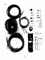
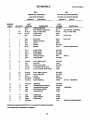


![10780-90006 - 10780A Laser Receiver for 5501A [Prefix 1948] (Mar](http://vs1.manualzilla.com/store/data/006009643_1-6e2f54ebb2199ef6df634558ba4c1bb6-150x150.png)