1
2.0
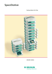
SpaceStation / SpaceCover / SpaceCom
Service Manual
Revision 2.0 English
0-
2.0
0
This Service Manual is valid for:
Designation
Part No.
SpaceStation without SpaceCom . . . . . . . . . . . . . . . . . 0871 3140
SpaceStation with SpaceCom . . . . . . . . . . . . . . . . . . . 0871 3142
SpaceCover standard . . . . . . . . . . . . . . . . . . . . . . . . . . . 0871 3147
SpaceCover comfort . . . . . . . . . . . . . . . . . . . . . . . . . . . 0871 3145
This Service Manual is available under
the following part number:
Designation
Part No.
Languages of this Manual
The Service Manual for this unit can be supplied in the following
languages:
Service Manual SpaceStation, English . . . . . . . . . . . . . 8713 9220
Designation
Part No.
German . . . . . . . . . . . . . . . . . . . . . . . . . . . . . . . . . . . . . . 8713 9210
English (US) . . . . . . . . . . . . . . . . . . . . . . . . . . . . . . . . 8713 9220U
French . . . . . . . . . . . . . . . . . . . . . . . . . . . . . . . . . . . . . . . 8713 9230
0- 2
SpaceStation, 2.0 gb
2.0
0-
Table of Contents
0
Important Preliminary Remarks
Service Work
Technical Safety Checks
Current Versions
Revision Service
Responsibility of the Manufacturer
Quality Management
Checks and Repair
Notes on ESD
Spare Parts and Test Equipment
Setting Off
List of Abbreviations
Page
Page
Page
Page
Page
Page
Page
Page
Page
Page
Page
0-5
0-5
0-5
0-5
0-6
0-6
0-6
0-6
0-7
0-7
0-9
Contact Persons
Technical Training
Entry for Technical Training
Ordering of Spare Parts and Test Equipment
Service Hotline
Return of Spare Parts and Test Equipment
Safety Officer
(§ 30 MPG)
Translation
Page
Page
Page
Page
Page
0 - 11
0 - 11
0 - 11
0 - 11
0 - 11
Page
Page
0 - 11
0 - 11
System Overview
Description
System Overview
Physical construction
Function
Unit Software
Service Program
SpaceOnline
(only required with SpaceStation with SpaceCom)
BCCshow
Technical Data
Options
Accessories
Page
Page
Page
Page
Page
Page
Page
Page
Page
Page
Page
Page
1-1
1-1
1-2
1-6
1 - 12
1 - 14
1 - 17
1 - 17
1 - 19
1 - 21
1 - 21
1 - 21
Unit Diagnosis / Calibration
General
Alarms and Error Codes
The Most Important Error Modes
Device Check
Device Check SpaceCom
Trouble Shooting
Page
Page
Page
Page
Page
Page
2-1
2-3
2-4
2-4
2-5
2-6
Disassembly / Assembly SpaceStation
General on the SpaceStation without SpaceCom
Tube Guide
Pole Clamp Guide
Housing Back Panel
Device Bracket
Power Supply
Release Button
Interface Board / Module Lock
Housing
Assembly / Installation
Page
Page
Page
Page
Page
Page
Page
Page
Page
Page
3-1
3-3
3-4
3-5
3-6
3-7
3 - 11
3 - 12
3 - 20
3 - 21
SpaceStation, 2.0 gb
0- 3
2.0
0
Table of Contents
Checks after Repair
Page
3 - 24
Disassembly / Assembly SpaceCom
General on the SpaceStation with SpaceCom
Battery Module
W-LAN Module
Tube Guide
Pole Clamp Guide
Housing Back Panel
Device Bracket
SPCO PCB
Further Disassembly
Assembly / Installation
Checks after Repair
Page
Page
Page
Page
Page
Page
Page
Page
Page
Page
Page
4-1
4-3
4-4
4-5
4-6
4-7
4 - 10
4 - 11
4 - 12
4 - 13
4 - 14
Disassembly / Assembly SpaceCover
General
Battery Compartment Cover
Battery Module
(Only SpaceCover comfort)
Handle
Housing Upper Part
Housing Back Panel
Loudspeaker
(Only SpaceCover comfort)
Processor PCB
(Only SpaceCover comfort)
Assembly / Installation
Checks after Repair
Page
Page
Page
Page
Page
Page
Page
Page
Page
Page
Page
Page
Page
5-1
5-3
5-4
5-4
5-5
5-6
5-8
5-9
5-9
5 - 10
5 - 10
5 - 11
5 - 12
Servicing the Unit
Cleaning
Servicing the Battery
Page
Page
6-1
6-1
Page
7-1
Technical Safety Check (TSC)
Procedural Instructions on the TSC
Test Equipment and Special Tools
Visual Inspection
Electrical Safety
according to IEC/EN 60601-1
or VDE 0750 and VDE 0751
Functional Inspection
Page
8-1
Page
Page
8-1
8-4
Test Equipment
Special Tools
Page
Page
9-1
9-1
Page
10 - 1
Page
Page
11 - 1
11 - 1
Page
12 - 1
Spare Parts List
Revision Documentation
Index
0- 4
Description of Version
Version List of the Individual Pages
SpaceStation, 2.0 gb
2.0
0-
Service Work
Technical Safety Checks
Important Preliminary Remarks
0
The present manual is for your information only. The possession of
this manual does not authorize the performance of service work.
Service tasks may only be executed by persons, who
-
have received appropriate training on the system from
B. Braun
-
are included in the revision service
-
possess the necessary test equipment and mechanical aids,
and
-
fulfill the personal requirements (training and knowledge).
The user is obliged to perform or to have performed the Technical
Safety Checks on those medial products for which these checks
have been prescribed by the manufacturer and to carry them out
according to the indications of the manufacturer as well as the
generally approved technical standards while adhering to the periods stated (§ 6 MP BetreibV).
B. Braun also recommends training on the Technical Safety
Checks, or to perform at least the steps indicated in the current
version of the manual, as:
-
the TSC requires that the instructions in the manuals are observed
-
the manuals are a reference for measurements
-
depending on the unit type, the Service Program must be
called which may lead to a dangerous unit condition in case
of inappropriate operation. Furthermore, a special service
connector may be necessary.
Current Versions
This manual version corresponds to the state when the manual
was written. B Braun reserves the right to make technical modifications. The state of the revision is indicated by the index number
in the footer of every page.
Revision Service
The possession of this manual does not automatically mean inclusion in the revision service. You will be included in the revision
service after:
SpaceStation, 2.0 gb
-
technical training by B. Braun Melsungen or
-
a written order placed with the sales department of B. Braun
(fee required).
0- 5
2.0
0
Important Preliminary Remarks
Responsibility of the Manufacturer
Quality Management
The manufacturer, person who assembles, installs or imports the
device can only be held responsible for safety, reliability and performance if
-
mounting, enhancements, new settings, changes or repairs
are carried out by duly authorized persons,
-
the electrical installation in the corresponding room meets
the requirements of the VDE 0107, VDE 0100 part 710 or
IEC 60364-7-710 and the national standards,
-
the device is used in accordance with the instructions for use
and the Service Manual,
-
the Technical Safety Checks are performed at regular intervals,
-
a current manual which corresponds to the revision state is
used when carrying out maintenance, repair and service,
-
the service technician takes part in the revision service,
-
the technician has participated in a technical training course
for the specific B. Braun unit.
B. Braun is certified in accordance with DIN EN ISO 9001 and
ISO 13485. This certification also includes maintenance and service.
The unit has the CE label. The CE label confirms that the device
corresponds to the “Directive of the Council for Medical Products
93/42/EC” of June 14, 1993.
Checks and Repair
Training may only be performed by B. Braun. The possession of the
manual does not authorize the performance of repairs. The instructions on electrostatic sensitive components (ESD standards)
must be observed.
After repair a device check or diagnosis is to be carried out.
Notes on ESD
0- 6
Semiconductors can be destroyed by electrostatic discharge. Especially MOS components can be damaged by interference from
electrostatic fields, even without discharge via contact. This type
of damage is not immediately recognizable. Unit malfunctions
can even occur after a longer period of operation.
SpaceStation, 2.0 gb
2.0
Important Preliminary Remarks
0
Each workstation must be equipped according to the recommendations with the necessary static protective measures, if ESD
components or boards are handled.
Each workstation must be equipped with a conductive table surface. The conductive surface, the soldering iron or the soldering
stations must be grounded via protective resistors.
Chairs must be of antistatic design. The floor or floor mats should
be of electrically conductive material.
Abb.: 0 - 1
Spare Parts and Test Equipment
Personnel must wear conductive wristbands which are connected
to a central ground potential via protective resistors, e.g. the
ground contact of a wall outlet. Furthermore it is recommended
that personnel wear cotton clothing and electrically conductive
shoes to prevent electrostatic charge.
Only use original spare parts from the manufacturer. Do not
tamper with assembly groups which can only be exchanged completely. The spare parts required are listed in Section 9.
Service personnel are responsible for the calibration of their test
equipment. Original test equipment can be calibrated at the
works of B. Braun. Further information is available upon request.
Setting Off
Additional notes and warnings are set off as follows:
Note
Is used for additional or special notes concerning information and
working steps.
CAUTION
Is used for working steps which may result in damage to the unit,
system or to a connected device.
WARNING
IS USED FOR WORKING STEPS WHICH MAY RESULT IN PERSONAL
INJURY.
References to chapters are shown as follows
(see “Setting Off“ ➨ pg. 0 - 8)
References to figures and tables are shown as follows
Fig.: 2 - 3 or Table 2 - 1
SpaceStation, 2.0 gb
0- 7
2.0
0
Important Preliminary Remarks
References to item numbers in figures are shown as follows
(Fig.: 1 - 1 / Item 1)
In this case “Fig.: 1 – 1“ is the figure number and “Item 1“ the item
number within the figure.
When the Service Manual is stored as pdf-file, these references
are displayed green. Click with the mouse button on a reference
to jump to the corresponding source.
Menu commands are described as:
Menu File.
0- 8
SpaceStation, 2.0 gb
2.0
Important Preliminary Remarks
List of Abbreviations
SpaceStation, 2.0 gb
0
Abbreviations which are not generally known, but are used in this
manual, are listed below.
CAN
Controller Area Network
CE
Communauté Européenne
CS
Calibration Step
DIN
Deutsche Industrie Norm
(German Industrial Norm)
EN
European Norm
ESD
Electrostatic Discharge
FuP
Function Microprocessor
IEC
International Electrotechnical
Commission
ISO
International Organization for
Standardization,
ISP
Infusomat® Space
ISPS
Infusomat® Space (Silicon)
ISPP
Infusomat® Space, (PVC)
KuP
Monitoring Microprocessor
LCD
Liquid Crystal Display
MOS
Short name of the following
company:
MOS Technology, Inc.
(Commodore Semiconductor
Group)
PCA
Patient Controlled Analgesia
PSP
Perfusor® Space
SP
Space (System)
SPC
SpaceCover
SPCC
SpaceCover comfort
SPCS
SpaceCover standard
SPCO
SpaceCom
SPCT
SpaceControl
SPS
SpaceStation
TS
Trouble Shooting
UTS
Unit Test Step
TSC
Technical Safety Check
0- 9
2.0
0
0 - 10
Important Preliminary Remarks
TEMP
Temperature
VDE
Verband der Elektrotechnik,
Elektronik und
Informationstechnik e.V.
(German Association of
engineers)
SpaceStation, 2.0 gb
2.0
0-
Contact Persons
0
Technical Training
Via local representative.
Entry for Technical Training
Application for a technical training course must be made via the
responsible representative.
Ordering of Spare Parts and Test Equipment
Please contact your local B. Braun subsidary.
International Technicians (Intercompany)
Nadja Machal
Fax:
+49 5661 / 75 -47 89
e-mail: [email protected]
Service Hotline
Karl Tippel, Tanja Kördel
Phone:
+49 5661 / 71 - 35 25
Fax:
+49 5661 / 71 - 35 26
e-mail: [email protected]
e-mail: [email protected]
Return of Spare Parts and Test Equipment
B. Braun Melsungen AG
Schwarzenberger Weg 73-79
Wareneingang Werk C
34 212 Melsungen
Germany
Safety Officer
(§ 30 MPG)
Dr. Ludwig Schütz
e-mail: [email protected]
Translation
PAS GmbH, Brückner GmbH, Germany
SpaceStation, 2.0 gb
0 - 11
2.0
0
Contact Persons
For your information:
0 - 12
SpaceStation, 2.0 gb
2.0
1-
Description
System Overview
1
The modular Space system is destined for treatment of an individual patient. It is designed for application on intensive care units
and in the surgery. The Space system is operated in hospitals
mainly by doctors and medically trained personnel.
The SpaceStation forms together with the SpaceCover an organization system. The Space system infusion and infusion syringe
pumps are attached and connected to the SpaceStation.
System Overview
The Space system is a modular design of modern infusion technology for stationary, mobile or private use. The key modules and
their connection to the peripheral devices are shown in Abb.: 1 1.
All the pump types, Perfusor® Space, Infusomat® Space and Infusomat® Space P, as well as the other devices of the system are of
modular design. Up to three pumps can be connected together using L rails on the bottom of the unit and grooves on the top. They
can then be fastened to a drip stand or appropriate rail using the
pole clamp.
1
2
The SpaceControl module can be used to extend operation. One
single pump can be inserted onto this module. The pump is then
connected via connectors to the module.
3
4
5
Abb.: 1 - 1 Space system
Legende zu Abb. 1 - 1:
ItemDesignation
1
SpaceCover
2
Infusion pump Infusomat® Space
3
Infusion syringe pump Perfusor® Space
4
SpaceControl
5
SpaceStation
SpaceStation, 2.0 gb
The SpaceStation module allows the set-up of a complete pump
system with up to 24 pumps. Up to four pumps can be installed in
every SpaceStation. The pumps are supplied with power via the
integrated power supply and the built-in connectors. The pumps
are connected to the optional SpaceCom via these connectors.
SpaceControl can also be integrated into the system.
Up to six SpaceStations can be set-up as a column with a total of
24 pumps. SpaceStation placed next to each other can be connected via special connecting cables, if the maximum number of
24 pumps in maximum three columns is not exceeded.
SpaceCover Standard or SpaceCover Comfort forms the top of
each column. Alarms are signalled by a row of LEDs and a loudspeaker in the SpaceCover Comfort.
1- 1
2.0
1
System Overview
Physical construction
SpaceStation without SpaceCom
The SpaceStation consists of the housing and the housing back
panel.
1
2
3
4
The power supply with power connector and power socket for another SpaceStation is installed on the right side in the housing.
The pumps in the SpaceStation are locked by 8 locking claws
which are built in the housing as subsystem “module locking”. This
subsystem also contains the locking for a SpaceCover or another
SpaceStation.
The pump is released with a release button on the left side of the
housing.
The pumps are connected to the system via the connectors “F2A“
to “F2D“ (from top to bottom) which are integrated in the interface board, while the SpaceStation is connected to other modules
via the connectors “F3“, “F4” and “F5”. The interface board with
connectors is installed on the left side in the housing.
6
5
Abb.: 1 - 2 SpaceStation, front view
Legende zu Abb. 1 - 2:
ItemDesignation
1
Pump lock
2
Connector “F5“
3
Module lock
4
Connector “F1B“ (mains output)
5
Tube guide
6
Connector “F2D“
1- 2
SpaceStation, 2.0 gb
2.0
System Overview
1
Four tube guides are clipped in on the left and right housing side.
2
A pole clamp guide for attachment and locking of the pole clamp
is located at the housing back panel.
1
5
4
3
Abb.: 1 - 3 SpaceStation without SpaceCom, rear view
Legende zu Abb. 1 - 3:
ItemDesignation
1
Pole clamp guide
2
Release button
3
Connector “F3“
4
Connector “F4“
5
Connector “F1A“ (power input)
SpaceStation, 2.0 gb
1- 3
2.0
1
System Overview
SpaceStation with SpaceCom
1
2
The physical construction of the SpaceStation front side with
SpaceCom corresponds exactly to the physical construction of the
SpaceStation without SpaceCom. The only visible difference is to
be found on the right side and the rear side.
Interfaces and a status- and alarm LED are located on the righthand side behind the connector cover and the W-LAN cover. A
battery module can be inserted in the battery compartment on
the rear side. The opening is covered by the battery compartment
cover.
4
A fan grid with fan is fitted on the left side of the battery compartment.
3
Abb.: 1 - 4 SpaceStation with SpaceCom, rear view
Legende zu Abb. 1 - 4:
ItemDesignation
1
Fan grid
2
Battery compartment with battery compartment cover
3
Connector cover
4
W-LAN cover for W-LAN- module
1- 4
SpaceStation, 2.0 gb
1.0
System Overview
1
SpaceCover standard
1
The SpaceCover standard housing consists mainly of the bottom
part and the upper part. A SpaceStation can be transported with
the carrying handle.
SpaceCover comfort
The physical construction of the SpaceCover comfort corresponds
to that of the SpaceCover standard. In addition to the SpaceCover
standard the following subsystems are installed in the SpaceCover
comfort:
-
The battery module (as option)
It is inserted from below in the battery compartment of the
housing bottom part. The opening is covered by the battery
compartment cover.
Legende zu Abb. 1 - 5:
ItemDesignation
-
Status and alarm display line
installed at the front of the housing upper part.
1
-
Operating and status display field
at the left side of the housing upper part.
Abb.: 1 - 5 SpaceCover comfort
SpaceCover comfort
SpaceStation, 1.0 gb
1- 5
2.0
1
System Overview
Function
SpaceStation without SpaceCom
The SpaceStation supplies the inserted pumps as well as a SpaceControl connected to the pumps with the required voltage. The
voltage is generated by the integrated power supply, which is connected to the supply mains via the connector “F1A” and a mains
cable or an upstream SpaceStation. The mains voltage is transmitted via the internal cabling to connector “F1B“ for connection
of a further SpaceStation.
The pumps are connected with connectors “F2A” to “F2D” to the
SpaceStation. These connectors provide the voltage supply, distribute the addresses in the Space system via a serial interface,
transfer data via a bus system (CAN bus) and transmit a staff call,
which may be pending.
Another SpaceStation inserted on top or a SpaceCover is integrated in the Space system via connector “F5“.
Connector “F4“ is used for connecting another SpaceStation or
further SpaceStation columns. An upstream SpaceStation or an
upstream SpaceStation column as well as accessories that may be
connected, such as a PCA button or a service connector, are connected to connector “F3“.
1- 6
SpaceStation, 2.0 gb
2.0
RX/TX_B
F1B
12VDC
Call
RX/TX
CAN
CAN_R
F5
CAN
System Overview
1
Mains
PCA
RX/TX
Call
Function processor
12VDC
3,3V
F2A
CAN
PCA
Call
4.9152 Mhz
12VDC
3,3V
F2B
3,3VDC
RX/TX
=
=
CAN
PCA
RX/TX
Call
=
12VDC
12VDC
3,3V
≈
F2C
CAN
230V AC
PCA
RX/TX
RX/TX_B
Call
RX/TX
CAN_R
F4
CAN
12VDC
3,3V
Call
RX/TX
PCA
F3
CAN
F2D
3.3VDC
Call
12VDC
3,3V
F1A Mains
Abb.: 1 - 6 Block diagram SpaceStation without SpaceCom
SpaceStation, 2.0 gb
1- 7
2.0
1
System Overview
SpaceStation with SpaceCom
The SpaceCom provides further interfaces and connections, e.g.
for a barcode scanner. These interfaces are depicted in Abb.: 1 - 7.
1
2
3
The battery module (option) serves to maintain the functions of
the SpaceStation in case of a voltage failure. An independent circuit in the battery module monitors the battery cells and controls
their charge condition. The SpaceStation must be covered with a
SpaceCover comfort with inserted battery module to guarantee
function of the battery module in the SpaceStation with SpaceCom.
4
5
6
7
8
Abb.: 1 - 7
Legende zu Abb. 1 - 7:
ItemDesignation
1
W-LAN slot
2
Status indicator (green)
3
Alarm indicator (red)
4
Ethernet (RJ 45) connection
5
PS/2 connection for barcode reader
6
RS232 connection
7
USB connection (slave)
8
USB connection (master)
1- 8
SpaceStation, 2.0 gb
2.0
System Overview
1
Abb.: 1 - 8 Block diagram SpaceStation with SpaceCom
SpaceStation, 2.0 gb
1- 9
1.0
1
System Overview
SpaceCover
The SpaceCover is connected to a SpaceStation with connector
“D1”.
With the SpaceCover standard this connector is used to connect
the CAN bus and a serial interface.
In the SpaceCover comfort this connector provides the voltage
supply, transmits a unique address in the Space system via a serial
interface, transfers data via a bus system (CAN bus) and transmits
a staff call, which may be pending.
The internal electronics controls the operator and status display
field, the loudspeaker as well as the status and alarm display line.
The status and alarm display line displays the collected messages
of the pumps in a column. The brightness is controlled dependent
on the environment.
The voltage supplied is converted to the internal voltages required
through a voltage transforming and monitoring circuit on the
processor PCB.
An independent circuit in the battery module monitors the battery
cells and controls their charge condition.
1 - 10
SpaceStation, 1.0 gb
1.0
1
System Overview
Loudspeaker
Function processor
LEDs
CAN RX/TX
CANtransceiver
CAN H
CAN L
RX/TX
12VDC
Operating unit
D1
12,0 Mhz
LEDs
Monitoring
12VDC
=
=
P1
Battery
module
12VDC battery
Brightness sensor
12VDC
Abb.: 1 - 9 Block diagram SpaceCover comfort
SpaceStation, 1.0 gb
1 - 11
2.0
1
System Overview
Unit Software
Approved Software Versions for SpaceStation
690A00SS01
Position
1 2 3 4 5 6 7 8 9 10
Digit
6 9 0 A 0 0 S S 0 2
Revision level
Hardware
-
Basic software
690A00SS02
-
Improved functions
Approved Software Versions for SpaceCom
Software group
Device type: SpaceStation
695C000001 / 695C000002
-
Basic software
Abb.: 1 - 10
695C010003
-
Adapted to hardware changes
695D010001
-
Adapted to the pump software
695E010001
-
Adapted to the pump software
Approved Software Versions for SpaceCover comfort
692A000001
-
Basic software
692A000002
-
Improved functions
692A000003
-
Expanded functions
692C000001
-
Adapted to the pump software
692E000001
-
1 - 12
Adapted to the pump software
SpaceStation, 2.0 gb
1.0
System Overview
1
Software Update
The instructions for updating the software are supplied with the
software itself.
CAUTION
If the device is disconnected while the software is being updated
or the device or PC is switched off, a component of the software
may be seriously damaged so that repairs are no longer possible.
In such a case the software can no longer be updated via the PC
and the device must be returned to B. Braun.
SpaceStation, 1.0 gb
1 - 13
2.0
1
System Overview
Service Program
Approved Version
Note
Please note that text and / or functions of the Service Program
may change depending on the software version. The following
screen illustrations are only examples and represent the state
when the manual was printed.
-
0.0.28.0
-
1.3.5
-
1.5.0
-
2.0.1
Connection
Before starting the Service Program the PC is to be connected to
the device via the RS232 SP interface cable.
Starting the Service Program
Installation and further operation of the Service Program is described in its separate instructions for use.
1.
Start the „HiBaSeD.exe“ program (History, Barcode, Service,
Drug list) on the PC. The Service Program is loaded and started and the initial window of the Service Program is displayed.
2.
Read the notes carefully.
3.
Mark the field “I accept all conditions” and then the field
“Yes” to confirm that you have read the notes.
Note
Click the field “English” to switch the language of the notes over
to English.
Abb.: 1 - 11
1 - 14
SpaceStation, 2.0 gb
2.0
System Overview
4.
1
Enter the password and confirm it by clicking the field “Start”.
Abb.: 1 - 12
The Service Program checks the PC interfaces for connected
devices of the Space system. Units that were found are displayed for a short moment on the screen.
Note
At present a connected SpaceStation is not displayed.
Abb.: 1 - 13
The work window of the Service Program appears on the
screen. All devices recognized are listed in the left column.
SpaceStation, 2.0 gb
1 - 15
2.0
1
System Overview
Abb.: 1 - 14
Service Program Version
1.
Open the “HiBaSeD“ window via Help ➨ Info .... The current
version of the Service Program is shown in this window.
2.
Close the window by clicking “OK”.
Abb.: 1 - 15
1 - 16
SpaceStation, 2.0 gb
2.0
System Overview
1
Compatibility List
1.
Open the “Unit - Compatibility“ window via Help ➨ Decice
compatibility. This window displays the compatibility of the
HiBaSeD-version and the unit software version.
2.
Close the window by clicking “OK”.
Abb.: 1 - 16
Quit the Service Program
1.
Exit the Service Program via File ➨ Exit.
SpaceOnline
(only required with SpaceStation with SpaceCom)
Approved Version
Note
Please note that text and / or functions of the SpaceOnline Program may change depending on the software version. The following screen illustrations are only examples and represent the state
when the manual was printed.
-
1.2.0
Connection
Before starting the SpaceOnline Program the PC is to be connected to the device via the RJ45 cross-over interface cable. In addition the PC-LAN connection must be configured with the correct
IP address (e.g. 192.168.100.1). Make sure that the first three digit
blocks, e.g. 192.168.100.xxx, of PC and the SpaceCom are identical.
Starting the SpaceOnline Program
1.
SpaceStation, 2.0 gb
Start the Internet Browser on your PC and enter the IP-address of the SpaceCom. The SpaceOnline start screen appears.
1 - 17
2.0
1
System Overview
Abb.: 1 - 17
Program Version
The program version is displayed in the header of the start screen.
Operation
The instructions for use contain a more detailed description of operation.
Exit the SpaceOnline Program
1.
1 - 18
Close the Internet Browser.
SpaceStation, 2.0 gb
2.0
System Overview
BCCshow
1
Approved Version
Note
Please note that text and / or functions of the BCCshow Program
may change depending on the software version. The following
screen illustrations are only examples and represent the state
when the manual was printed.
-
3.26
Connection
Before starting the BCCshow Program the PC is to be connected
to the device via the RS232 SPCO (crossed) interface cable.
Connection Settings
1.
Open the „BCCshow.ini“ file after having installed the program.
2.
Check the line „ComPort=X“.
3.
Substitute the X for the current ComPort number, e.g. “1”.
Starting the BCCshow Program
1.
2.
Start the BCCshow program. The start screen appears.
Invoke the display of the connected system via System ➨
Start.
The SpaceStation with all pumps inserted and the set data is
displayed.
SpaceStation, 2.0 gb
1 - 19
2.0
1
System Overview
Abb.: 1 - 18
Program Version
1.
Open the „Information" window via Info ➨ Version. The current program version is displayed in this window.
2.
Close the window by clicking “OK”.
Abb.: 1 - 19
1 - 20
SpaceStation, 2.0 gb
2.0
1
System Overview
Technical Data
All technical data is indicated in the instructions for use.
Options
The functions of the individual options are detailed in the instructions for use.
SpaceStation with SpaceCom
Designation
Part No.:
SpaceCom retrofit kit. . . . . . . . . . . . . . . . . . . . . . . . . . . 0871 3160
The optional SpaceCom provides additional interfaces, such
as Ethernet RJ45, RS232. A SpaceStation without SpaceCom
can be upgraded with this retrofit kit.
Accessories
Designation
Part No.
Charger SP . . . . . . . . . . . . . . . . . . . . . . . . . . . . . . . . . . . 0871 3170
battery charging station
Connecting cable staff call SP . . . . . . . . . . . . . . . . . . . 0871 3232
Power supply cable 12 V . . . . . . . . . . . . . . . . . . . . . . . . 0871 3231
for ambulance cars
Interface cable CAN SP . . . . . . . . . . . . . . . . . . . . . . . . . 0871 3230
Interface cable RS232 SP . . . . . . . . . . . . . . . . . . . . . . . 0871 3234
Interface cable RS232 SPCO (crossed) . . . . . . . . . . . . 0871 3237
Converter RS232 SP . . . . . . . . . . . . . . . . . . . . . . . . . . . 0871 3238
W-LAN card . . . . . . . . . . . . . . . . . . . . . . . . . . . . . . . . . . 0871 3184
Connecting cable SP 60cm . . . . . . . . . . . . . . . . . . . . . . 0871 3210
for connecting two columns
Connecting cable SP 120cm . . . . . . . . . . . . . . . . . . . . 0871 3215
for connecting two columns
PoleClamp SP . . . . . . . . . . . . . . . . . . . . . . . . . . . . . . . . . 0871 3130
The PoleClamp SP is a holder for one
or several Space system pumps.
Universal clamp . . . . . . . . . . . . . . . . . . . . . . . . . . . . . . . .3452 1151
SpaceStation, 2.0 gb
1 - 21
1.0
1
System Overview
For your information:
1 - 22
SpaceStation, 1.0 gb
2.0
2-
Unit Diagnosis / Calibration
2
General
WARNING
WHILE TESTING THE UNIT AND TROUBLE SHOOTING THE OPERATOR/SERVICE TECHNICIAN MUST WORK WITH VOLTAGES UP TO
115 / 230 V AC. THESE VOLTAGES MAY CAUSE INJURIES WHICH
ARE DANGEROUS TO LIFE AND LIMB. THE NATIONAL AND INTERNATIONAL SAFETY REGULATIONS ARE TO BE ADHERED TO.
Before each disassembly of a unit subsystem check the connectors, plug contacts and connections for corrosion and tight fit.
These fault types are not described again in the following trouble
shooting list.
The following equipment is necessary for testing the SpaceStation
without SpaceCom and/or performing trouble shooting:
-
PC
-
Service connector SP
-
Service Program HiBaSeD
-
Interface cable RS232 SP
-
Space system pump
-
SpaceCover comfort (for unit diagnosis of the SpaceStation)
The following additional equipment is necessary for testing the
SpaceStation with SpaceCom and/or performing trouble shooting:
-
Interface cable CAN SP
-
Interface cable RS232 SPCO (crossed)
-
Interface cable RJ45 cross-over
CAUTION
Take special care when carrying out measurements on an open
and switched-on unit. Short circuits and wrong measuring methods can cause serious damage to or destroy the subsystems of the
device.
SpaceStation, 2.0 gb
2- 1
1.0
2
Unit Diagnosis / Calibration
The unit check, calibration and trouble shooting are subdivided
into numbered working steps (Unit Test Step UTS, Calibration Step
CS, Trouble Shooting TS) and are based on each other.
Beginning with UTS 1 the operation described here has to be executed. The consequences of the steps performed are listed in the
“Function“ column. If the result corresponds to the consequence,
the working step must be carried out to which reference is made
in the column “If yes”. If the result does not correspond with the
function described, the working step in column “If no” is to be executed.
One example is given in Abb.: 2 - 1.
UTS
Activity
Function
If yes
If no
1
UTS 2
2
UTS 3
3
UTS 4
4
UTS 5
TS 4
UTS 3
TS 2
2
TS 3
TS 4
3
UTS 3
4
UTS 4
5
UTS 4
TS 1
5
Model table 1
TS
1
Activity
Function
TS 4
Model table 2
Abb.: 2 - 1 Model tables
Steps for which additional information is required are described
hereafter in detail.
2- 2
SpaceStation, 1.0 gb
2.0
Unit Diagnosis / Calibration
Alarms and Error Codes
2
SpaceStation without SpaceCom
Neither alarms nor error codes are actually displayed on the
SpaceStation without SpaceCom.
SpaceStation with SpaceCom
Alarm
Possible Cause
1
SpaceComAlarm indicator (red) is on
SpaceCom is still starting
2
SpaceComAlarm indicator (red) flashes
A serious internal fault was detected in
the system
Fault Clearance
Carry out a device check (see „Device
Check“ ➨ S. 2 - 4)
Table 2 - 1 Alarms on the SpaceCom
SpaceCover comfort
Alarm
Possible Cause
Fault Clearance
1
One of the diodes of the status- and
alarm display line is on or flashes
A message or an alarm of a pump is displayed
2
The status indicator (on the right-hand
side of the On-/Off-button) flashes red
System not properly configured
3
The status indicator (on the right-hand A serious internal fault was detected in
side of the On-/Off-button) lights up red the system
Carry out a device check (see „Device
Check“ ➨ S. 2 - 4)
4
The first LED in the top charge condition Battery module of theSpaceCover comdisplay of the operator and status display fort nearly discharged (type: pre-alarm)
field of the SpaceCover comfort flashes
yellow
Connect device to voltage supply
5
The first LED in the bottom charge condi- Battery module of theSpaceCom nearly
tion display of the operator and status discharged (type: pre-alarm)
display field of the SpaceCover comfort
flashes yellow
Connect device to voltage supply
6
The first LED in the top charge condition Battery module of the SpaceCover com- Connect device to voltage supply
display of the operator and status display fort discharged
field of the SpaceCover comfort flashes
red
7
The first LED in the bottom charge condi- Battery module of the SpaceCom distion display of the operator and status charged
display field of the SpaceCover comfort
flashes red
Check configuration
Connect device to voltage supply
Table 2 - 2 Alarms of the SpaceCover comfort (Part 1 of 2)
SpaceStation, 2.0 gb
2- 3
2.0
2
Unit Diagnosis / Calibration
Alarm
Possible Cause
Fault Clearance
8
The first LED in the top charge condition Battery module of the SpaceCover com- Replace battery module
display of the operator and status display fort defective or too old
field of the SpaceCover comfort lights up
red
9
The first LED in the bottom charge condi- Battery module of the SpaceCom defec- Replace battery module
tion display of the operator and status tive or too old
display field of the SpaceCover comfort
lights up red
Table 2 - 2 Alarms of the SpaceCover comfort (Part 2 of 2)
The Most Important Error Modes
The following list specifies the most important error modes and
their clearance.
Note
The error list is in preparation.
Device Check
UTS
Activity
1
Detach or loosen all connections and devices from
the SpaceStation
UTS 2
2
Connect the SpaceStation via the mains cable to
the mains
UTS 3
3
Insert one pump after the other in each slot
4
Function
If yes
If no
The pump is locked
UTS 4
TS 1
The pump can be released at any slot
UTS 5
TS 1
5
Plug service connector SP on connector “F3”
6
Insert the pump in the topmost slot and trigger a
staff call
The red LED of the service connector SP lights up
UTS 7
TS 4
7
Remove the pump while it is switched on
The red LED of the service connector SP goes out
UTS 8
TS 4
8
Insert the switched-on pump in each other slot
The red LED of the service connector SP lights up
when the lock engages
UTS 9
TS 4
9
A SpaceCover comfort with SpaceStation is installed
UTS 10
UTS 20
10
Mount and lock the SpaceCover comfort on the
SpaceStation
All luminous fields of the status and alarm display
line light up briefly during the self-test
UTS 11
TS 5
A short audible alarm sounds
UTS 12
TS 7
11
UTS 6
Table 2 - 3 Device check (Part 1 of 2)
2- 4
SpaceStation, 2.0 gb
2.0
Unit Diagnosis / Calibration
UTS
Activity
2
Function
If yes
If no
12
All LEDs of the operator and status display field light
up briefly
UTS 13
TS 5
13
The green LED on the operator and status display
field lights up
UTS 14
TS 5
14
When the battery module is inserted the charge
condition is displayed in the top charge status display of the operator and status display field
UTS 15
TS 9
The loudness changes
UTS 16
TS 11
15
Change loudness of the alarm tone
16
Insert pump in the topmost slot and start an infu- The infusion is displayed green in the status and
sion
alarm display line
UTS 17
TS 13
17
Insert the pump in each other slot and start an in- The infusion is displayed green in the status and
fusion
alarm display line
UTS 18
TS 14
18
Trigger an alarm on the pump
UTS 19
TS 15
19
If a SpaceCom is integrated in the SpaceStation
carry out the device check according to Chapter
„Device Check SpaceCom“ (➨ S. 2 - 5).
20
Detach or loosen all connections and devices from
the SpaceStation
The alarm is displayed red (orange in case of a prealarm) in the status and alarm display line
UTS 20
This step terminates
the device check
Table 2 - 3 Device check (Part 2 of 2)
Device Check SpaceCom
GSCOM
Activity
1
Disconnect the SpaceStation from the mains and
switch off a SpaceCover comfort which may be
fitted
2
Function
If yes
If no
UTS-COM 2
A battery module is installed in the SpaceStation UTS-COM 3 UTS-COM 4
3
Insert a battery module in the SpaceStation
4
Connect the SpaceStation to the mains
UTS-COM 4
Fan in the housing back panel starts running for
appr. 1 sec.
UTS-COM 5
TS 17
5
The status indicator (green) of the SpaceCom
lights up
UTS-COM 6
TS 20
6
The alarm indicator (red) of the SpaceCom lights UTS-COM 7
up for approx. 1 minute and goes out
TS 20
Table 2 - 4 Device check SpaceCom (Part 1 of 2)
SpaceStation, 2.0 gb
2- 5
2.0
2
Unit Diagnosis / Calibration
GSCOM
Activity
Function
If yes
The charge condition of the battery module is dis- UTS-COM 8
played in the bottom charge condition display of
the operator and status display field of the SpaceCover comfort
7
8
Connect the SpaceStation with the interface cable RJ45 cross-over via the Ethernet (RJ45) connection of the SpaceCom to a PC
9
Start the SpaceOnline Program (see „SpaceOnli- The data of the SpaceStation and the pumps inne“ ➨ S. 1 - 17)
serted is displayed on the PC monitor
UTS-COM
10
10
Connect the SpaceStation with the interface cable RS232 SPCO (crossed) via the RS 232 connector of the SpaceCom to a PC
UTS-COM
11
11
Start the BCCshow Program (see „BCCshow“ ➨
S. 1 - 19).
12
Detach or loosen all connections and devices
from the SpaceStation
If no
TS 22
UTS-COM 9
The data of the SpaceStation and the pumps inserted is displayed on the PC monitor
UTS-COM
12
TS 20
TS 20
This step terminates the
device check
Table 2 - 4 Device check SpaceCom (Part 2 of 2)
Trouble Shooting
Note
The following trouble shooting cannot be carried out independently. It is based on the precise observance of the steps for the device check (see „Device Check“ ➨ S. 2 - 4). From there reference
is made to the corresponding trouble shooting steps.
TS
Activity
Function
If yes
1
Replace the module lock
2
Check the voltage 12 V (-0.6 V / +3.5 V) DC at the The voltage is measured
interface board plug contacts (connection power
supply – interface board)
3
Replace power supply
UTS 4
4
Replace interface board
UTS 4
If no
UTS 3
TS 4
TS 3
Table 2 - 5 Trouble shooting (Part 1 of 2)
2- 6
SpaceStation, 2.0 gb
2.0
Unit Diagnosis / Calibration
TS
Activity
5
Exchange processor PCB SPCC
6
Replace interface board in the SpaceStation
7
Replace loudspeaker
8
Exchange processor PCB SPCC
9
Replace interface board in the SpaceStation
10
Exchange the housing upper part SPCC
Function
If yes
If no
All luminous fields of the status and alarm display
line light up briefly during the self-test
All LEDs of the operator and status display field light
up briefly
The green LED on the operator and status display
field lights up
UTS 10
TS 6
UTS 10
A short audible alarm sounds
The charge state of the battery module is displayed
on the operator and status display field
Exchange the housing upper part SPCC
Exchange processor PCB SPCC
13
Exchange processor PCB SPCC
14
Replace interface board in the SpaceStation
15
Exchange processor PCB SPCC
16
Replace interface board in the SpaceStation
17
The fan is running
Pull off the fan connecting cable on the SPCO
board and trigger the fan with 12 V DC. Connect
the (+) pole to the connector pole with red wires
and the (-) pole to the connector pole with black
wires
18
Exchange fan
The loudness changes
UTS 15
TS 10
UTS 16
TS 12
UTS 16
The infusion is displayed green in the status and
alarm display line
UTS 18
TS 14
UTS 18
The alarm is displayed red in the status and alarm
display line
UTS 20
TS 16
UTS 20
TS 19
TS 18
UTS-COM 5
The status indicator (green) of the SpaceCom lights
up
Replace the SPCO board
TS 8
UTS 15
11
20
UTS 14
UTS 14
12
19
2
TS 20
TS 21
UTS-COM 5
21
Replace interface board in the SpaceStation
UTS-COM 5
22
Replace battery module of the SpaceStation
The charge condition of the battery module is dis- UTS-COM 8
played in the bottom charge condition display of
the operator and status display field of the SpaceCover comfort
TS 23
23
Replace the SPCO board
The charge condition of the battery module is dis- UTS-COM 8
played in the bottom charge condition display of
the operator and status display field of the SpaceCover comfort
TS 24
24
Replace interface board in the SpaceStation
UTS-COM 8
Table 2 - 5 Trouble shooting (Part 2 of 2)
SpaceStation, 2.0 gb
2- 7
2.0
2
Unit Diagnosis / Calibration
For your information:
2- 8
SpaceStation, 2.0 gb
2.0
3-
Disassembly / Assembly SpaceStation
SpaceStation, SpaceCover
3.1
General on the SpaceStation without SpaceCom
3
Remarks on Disassembly / Assembly of the SpaceStation without SpaceCom
WARNING
DURING DISASSEMBLY AND ASSEMBLY THE OPERATOR/SERVICE
TECHNICIAN MUST WORK WITH VOLTAGES UP TO 115 / 230 V AC.
THESE VOLTAGES MAY CAUSE INJURIES WHICH ARE DANGEROUS
TO LIFE AND LIMB. THE NATIONAL AND INTERNATIONAL SAFETY
REGULATIONS ARE TO BE ADHERED TO. THE MAINS CABLE IS TO
BE REMOVED.
Before disassembling the unit, the system must be checked (see
„Device Check“ ➨ S. 2 - 4) to isolate the part to be exchanged.
All necessary steps to disassemble or dismount the complete unit
with all its subsystems and spare parts are detailed in the following description. Steps that are not necessary can be skipped.
Note
Special screws for plastic housings are used in this unit. Pay attention to the corresponding notes when you fit the screws.
SpaceStation, 2.0 gb
3- 1
2.0
3
Disassembly / Assembly SpaceStation
Service Parts and Screw Kit
All small parts, such as cover caps, are contained in a SpaceStation service part kit.
Designation
Ord. No.
Service part kit SpaceStation . . . . . . . . . . . . . . . . . . . . 3477 4335
with:
Release button
Release seal
Seal M-2K
Cover cap for housing
Cover cap for handle
Housing foot SPS
Seal, mains F1A
Pole clamp lever
Pole clamp spring
O-ring 6.07 x 1.78
O-ring 12.0 x 2.0
All screws used in the device are included in a SpaceStation screw
kit.
Designation
Ord. No.
Screw kit SpaceStation . . . . . . . . . . . . . . . . . . . . . . . . . 3477 4343
Screw EJOT 30x9 WN 5452 TORX 10IP A2
Screw EJOT 30x12 WN 5452 TORX 10IP A2
Screw EJOT 30x16 WN 5451 TORX 10IP A2
Screw M5x45 A2 DIN912 TORX 25
Countersunk screw M5x12 TORX 25
Fillister-head screw M5x12 EN-ISO14583 A2
Nut M4
Insulating washer M3
Washer M4
Washer M5
Serrated lock washer M4
Serrated lock washer M5
SpaceStation without SpaceCom
3- 2
SpaceStation, 2.0 gb
1.0
Disassembly / Assembly SpaceStation
3.2
Tube Guide
Designation
3
Ord. No.
Tube guide SPS . . . . . . . . . . . . . . . . . . . . . . . . . . . . . . . 3477 4394
(20 pieces)
Disassembly
1
1.
Press the rotary knob of the tube guide out and pull the tube
guide (Abb.: 3 - 1 / Item 1) out of the housing.
Note
When the tube guide is broken, remove the remaining parts from
the housing.
Abb.: 3 - 1
Legende zu Abb. 3 - 1:
ItemDesignation
1
Tube guide
SpaceStation, 1.0 gb
3- 3
1.0
3
3.3
Disassembly / Assembly SpaceStation
Pole Clamp Guide
Designation
Ord. No.
Pole clamp guide SPS . . . . . . . . . . . . . . . . . . . . . . . . . . . 3452 1135
Pole clamp lever
(see „Service Parts and Screw Kit“ ➨ S. 3 - 2)
Pole clamp spring
(see „Service Parts and Screw Kit“ ➨ S. 3 - 2)
Screws
(see „Service Parts and Screw Kit“ ➨ S. 3 - 2)
Disassembly
1.
Loosen three screws (Abb.: 3 - 2 / Item 2) and remove the
screws together with the pole clamp guide (Abb.: 3 - 2 /
Item 1).
2.
Remove pole clamp lever (Abb.: 3 - 2 / Item 4) and pole clamp
spring (Abb.: 3 - 2 / Item 3).
1
2
4
3
Abb.: 3 - 2
Legende zu Abb. 3 - 2:
ItemDesignation
1
Pole clamp guide
2
Countersunk screw M5x12 TORX 25
3
Pole clamp spring
4
Pole clamp lever
3- 4
SpaceStation, 1.0 gb
1.0
Disassembly / Assembly SpaceStation
3.4
Housing Back Panel
Designation
3
Ord. No.
Housing back panel SPS . . . . . . . . . . . . . . . . . . . . . . . . 3452 1089
Cover cap and screws
(see „Service Parts and Screw Kit“ ➨ S. 3 - 2)
Disassembly
2
1
3
1.
Pierce ten cover caps (Abb.: 3 - 3 / Item 3) with a screwdriver
and pull caps out.
2.
Loosen nine screws (Abb.: 3 - 3 / Item 2) and remove screws
carefully together with the back panel (Abb.: 3 - 3 / Item 4)
from the housing.
Note
Lift the housing back panel carefully at the bottom over the seat
of the pole clamp guide and push the back panel over the housing
notch (Abb.: 3 - 3 / Item 1).
4
Abb.: 3 - 3
Legende zu Abb. 3 - 3:
ItemDesignation
1
Housing notch
2
Screw EJOT 30x9 WN 5452 TORX 10IP A2
3
Cover cap
4
Housing back panel
SpaceStation, 1.0 gb
3- 5
2.0
3
3.5
Disassembly / Assembly SpaceStation
Device Bracket
Designation
Ord. No.
Device bracket SPS . . . . . . . . . . . . . . . . . . . . . . . . . . . . . 3452 1127
Screws
(see „Service Parts and Screw Kit“ ➨ S. 3 - 2)
Disassembly
1.
Loosen five screws (Abb.: 3 - 4 / Item 2) and remove screws
together with the serrated lock washers (Abb.: 3 - 4 / Item 1)
and the device bracket (Abb.: 3 - 4 / Item 3).
1
2
3
Abb.: 3 - 4
Legende zu Abb. 3 - 4:
ItemDesignation
1
Serrated lock washer M5
2
Screw M5x45 A2 DIN912 TORX 25
3
Device bracket
3- 6
SpaceStation, 2.0 gb
2.0
Disassembly / Assembly SpaceStation
3.6
Power Supply
Designation
3
Ord. No.
Power supply SPS . . . . . . . . . . . . . . . . . . . . . . . . . . . . . . 3452 1097
Connector holder, mains, SPS . . . . . . . . . . . . . . . . . . . . 3452 1143
Cover cap, screws, washer,
serrated lock washers and nuts
(see „Service Parts and Screw Kit“ ➨ S. 3 - 2)
Mains seal, bottom
(see „Service Parts and Screw Kit“ ➨ S. 3 - 2)
Disassembly
1
2
1.
Pierce two cover caps (Abb.: 3 - 5 / Item 1) with a screwdriver
and pull caps out.
2.
Unscrew two screws (Abb.: 3 - 5 / Item 2) and remove them
from the mains connector holder.
Abb.: 3 - 5
Legende zu Abb. 3 - 5:
ItemDesignation
1
Cover cap
2
Screw EJOT 30x9 WN 5452 TORX 10IP A2
Note
Note the position of the protective conductor cable on the
grounding bolt.
3.
5
4
3
2
Loosen the nut (Abb.: 3 - 6 / Item 5) and remove nut together
with the serrated lock washer (Abb.: 3 - 6 / Item 4), washer
(Abb.: 3 - 6 / Item 3), the protective conductor cable to the
power supply (Abb.: 3 - 6 / Item 1) and the protective conductor cable to connector “F1B“ (Abb.: 3 - 6 / Item 2) from
the grounding bolt.
1
Abb.: 3 - 6
Legende zu Abb. 3 - 6:
ItemDesignation
1
Cable lug for connection to the power supply
2
Cable lug for connection to connector “F1B“
3
Washer M4
4
Serrated lock washer M4
5
Nut M4
SpaceStation, 2.0 gb
3- 7
2.0
3
Disassembly / Assembly SpaceStation
4.
Loosen the nut (Abb.: 3 - 7 / Item 4) and remove nut together
with the serrated lock washer (Abb.: 3 - 7 / Item 3), washers
(Abb.: 3 - 7 / Item 1) and the protective conductor cable to
connector “F1A“ (Abb.: 3 - 7 / Item 2) from the grounding
bolt.
5.
Carefully pull off the connector of the power supply wires
from the interface board.
Note
Note or mark the polarity.
4
3
1
2
1
Abb.: 3 - 7
Legende zu Abb. 3 - 7:
ItemDesignation
1
Washer M4
2
Cable lug for connection to connector “F1A“
3
Serrated lock washer M4
4
Nut M4
6.
Loosen two screws (Abb.: 3 - 8 / Item 1) and take them out of
the power supply housing (connector).
1
Abb.: 3 - 8
Legende zu Abb. 3 - 8:
ItemDesignation
1
3- 8
Screw EJOT 30x9 WN 5452 TORX 10IP A2
SpaceStation, 2.0 gb
1.0
Disassembly / Assembly SpaceStation
7.
3
Loosen four screws (Abb.: 3 - 9 / Item 1) and take the power
supply (Abb.: 3 - 9 / Item 2) with the mains connector holder
out of the housing.
1
2
Abb.: 3 - 9
Legende zu Abb. 3 - 9:
ItemDesignation
1
Screw EJOT 30x12 WN 5451 TORX 10IP A2
2
Power supply
SpaceStation, 1.0 gb
3- 9
1.0
3
Disassembly / Assembly SpaceStation
Disassembly
1.
Loosen three screws (Abb.: 3 - 10 / Item 3) and remove
screws together with the mains connector holder (Abb.: 3 10 / Item 1) and the mains seal F1A (Abb.: 3 - 10 / Item 2)
from the power supply.
1
2
3
Abb.: 3 - 10
Legende zu Abb. 3 - 10:
ItemDesignation
1
Mains connector holder
2
Mains seal F1A
3
Screw EJOT 30x9 WN 5452 TORX 10IP A2
3 - 10
SpaceStation, 1.0 gb
1.0
Disassembly / Assembly SpaceStation
3.7
Release Button
Designation
3
Ord. No.
Release button and release seal
(see „Service Parts and Screw Kit“ ➨ S. 3 - 2)
Disassembly
1.
Press four release buttons (Abb.: 3 - 11 / Item 1) carefully
from the inside from the locking shaft using a screwdriver
and pull the buttons out of the housing.
Note
Check the release buttons for damage, especially within the notch
area, before fitting the buttons.
3
Abb.: 3 - 11
Legende zu Abb. 3 - 11:
ItemDesignation
1
Release button
SpaceStation, 1.0 gb
3 - 11
1.0
3
3.8
Disassembly / Assembly SpaceStation
Interface Board / Module Lock
Designation
Ord. No.
Interface board SPS . . . . . . . . . . . . . . . . . . . . . . . . . . . . 3452 1100
with connectors
Connector holder, data, SPS . . . . . . . . . . . . . . . . . . . . . 3452 1160
Module lock SPS . . . . . . . . . . . . . . . . . . . . . . . . . . . . . . . 3452 1119
Cover cap, screws, insulating washers, O-rings
(see „Service Parts and Screw Kit“ ➨ S. 3 - 2)
Disassembly
1
2
1.
Move the lock towards the SpaceCover or another SpaceStation in the closed position.
2.
Loosen one screw (Abb.: 3 - 12 / Item 1) of the module lock
and remove it out of the housing.
3.
Pull the module lock sleeve (Abb.: 3 - 12 / Item 3) out of the
housing.
4.
Check the O-ring (Abb.: 3 - 12 / Item 2) for damage, and remove it out of the housing if necessary.
3
Abb.: 3 - 12
Legende zu Abb. 3 - 12:
ItemDesignation
1
Module lock screw
2
O-Ring 6.07 x x1.78
3
Module lock sleeve
3 - 12
SpaceStation, 1.0 gb
1.0
Disassembly / Assembly SpaceStation
3
5.
Loosen two screws (Abb.: 3 - 13 / Item 1) and remove screws
together with the insulating washers (Abb.: 3 - 13 / Item 3)
from the interface board (Abb.: 3 - 13 / Item 2).
6.
Put the interface board carefully aside for all further activities.
Note
1
Take care not to squeeze the interface board ribbon cable.
2
3
Abb.: 3 - 13
Legende zu Abb. 3 - 13:
ItemDesignation
1
Screw EJOT 30x9 WN 5452 TORX 10IP A2
2
Interface board
3
Insulating washer M3
SpaceStation, 1.0 gb
3 - 13
1.0
3
Disassembly / Assembly SpaceStation
7.
Release all rotary knobs (Abb.: 3 - 14 / Item 1) of the module
lock.
1
Note
Put a release button on the release shaft without engaging it to
unlock the rotary knobs. To lock the rotary knobs press them simultaneously in by hand per slot.
8.
Press 8 seals M-2K (Abb.: 3 - 14 / Item 2) carefully out of the
housing, press the rotary knobs in the locking position and
pull the seals M-2K off the rotary knobs.
2
Abb.: 3 - 14
Legende zu Abb. 3 - 14:
ItemDesignation
1
Release button
2
Seal M-2K
3 - 14
SpaceStation, 1.0 gb
1.0
3
Disassembly / Assembly SpaceStation
9.
Pierce two cover caps (Abb.: 3 - 15 / Item 2) with a screwdriver and pull caps out.
10. Loosen two screws (Abb.: 3 - 15 / Item 1) and remove them
out of the data connector holder.
1
2
Abb.: 3 - 15
Legende zu Abb. 3 - 15:
ItemDesignation
1
Screw EJOT 30x9 WN 5452 TORX 10IP A2
2
Cover cap
11. Loosen two screws (Abb.: 3 - 16 / Item 2) and remove them
from the connector board F5 (Abb.: 3 - 16 / Item 1).
1
12. Press the connector board F5 carefully out of the housing.
2
Note
The connector board F5 is integrated in the interface board.
Abb.: 3 - 16
Legende zu Abb. 3 - 16:
ItemDesignation
1
Connector board F5
2
Screw EJOT 30x9 WN 5452 TORX 10IP A2
SpaceStation, 1.0 gb
3 - 15
1.0
3
Disassembly / Assembly SpaceStation
13. Loosen one screw (Abb.: 3 - 17 / Item 1) and remove it out of
the data connector holder (Abb.: 3 - 17 / Item 2).
1
2
Abb.: 3 - 17
Legende zu Abb. 3 - 17:
ItemDesignation
1
Screw EJOT 30x9 WN 5452 TORX 10IP A2
2
Data connector holder
3 - 16
SpaceStation, 1.0 gb
1.0
Disassembly / Assembly SpaceStation
3
14. Loosen three screws (Abb.: 3 - 18 / Item 4) and remove
screws together with the module lock (Abb.: 3 - 18 / Item 1),
the interface board (Abb.: 3 - 18 / Item 2) and the data connector holder (Abb.: 3 - 18 / Item 3) out of the housing.
1
Note
Note the ribbon cable length to the interface board when dismounting the data connector holder. The ribbon cable must not
be kinked.
2
4
3
Abb.: 3 - 18
Legende zu Abb. 3 - 18:
ItemDesignation
1
Module lock
2
Interface board
3
Data connector holder
4
Screw EJOT 30x9 WN 5452 TORX 10IP A2
SpaceStation, 1.0 gb
3 - 17
1.0
3
Disassembly / Assembly SpaceStation
Disassembly
1
1.
Loosen fours screws (Abb.: 3 - 19 / Item 1) and remove
screws together with the insulating washers (Abb.: 3 - 19 /
Item 2).
2.
Press connectors F3 (Abb.: 3 - 20 / Item 2) and F4 (Abb.: 3 20 / Item 3) carefully out of the data connector holder
(Abb.: 3 - 20 / Item 1).
2
Abb.: 3 - 19
Legende zu Abb. 3 - 19:
ItemDesignation
1
Screw EJOT 30x9 WN 5452 TORX 10IP A2S
2
Insulating washer M3
Note
1
3
The connectors F3 and F4 are integrated in the interface board.
2
Abb.: 3 - 20
Legende zu Abb. 3 - 20:
ItemDesignation
1
Data connector holder
2
Connector F3
3
Connector F4
3 - 18
SpaceStation, 1.0 gb
1.0
Disassembly / Assembly SpaceStation
3.
1
3
Press the connector board lockings (Abb.: 3 - 21 / Item 3)
F2A, F2B, F2C, and F2D carefully aside, push the connectors
downwards, pull them out of the module lock (Abb.: 3 - 21 /
Item 1) and remove them with the interface board (Abb.: 3 21 / Item 2) from the module lock.
Note
The connectors F2A, F2B, F2C, and F2D are connected to each other and integrated in the interface board.
3
2
Abb.: 3 - 21
Legende zu Abb. 3 - 21:
ItemDesignation
1
Module lock
2
Connector board
3
Connector board lockings
SpaceStation, 1.0 gb
3 - 19
1.0
3
3.9
Disassembly / Assembly SpaceStation
Housing
Designation
Ord. No.
Housing SPS . . . . . . . . . . . . . . . . . . . . . . . . . . . . . . . . . . 3452 1070
incl. mains seal F1B
Screws, seals and housing foot SPS
(see „Service Parts and Screw Kit“ ➨ S. 3 - 2)
Disassembly
3
2
1.
Pull two housing feet (Abb.: 3 - 22 / Item 1) out of the housing.
2.
Remove four release seals (Abb.: 3 - 22 / Item 2) from the
housing.
Note
The seals are self-adhesive. Remove any adhesive residues after
disassembly.
3.
Remove mains seal F1B (Abb.: 3 - 22 / Item 3) out of the
housing.
Note
The housing must not be disassembled further. The seals behind
the corner profiles on the right and left side can only be inserted
correctly by means of special tools.
1
Abb.: 3 - 22
Legende zu Abb. 3 - 22:
ItemDesignation
1
Housing foot SPS
2
Release seal
3
Mains sealF1B
3 - 20
SpaceStation, 1.0 gb
1.0
Disassembly / Assembly SpaceStation
3.10 Assembly / Installation
3
Assembly or installation of the modules and subsystems is done in
reverse order of disassembly. Special steps to be observed are described hereafter in detail.
Only new cover caps are to be used.
Special Screws
Special screws for plastic housings are used in this unit. The
screws are not self-cutting but produce a thread in the plastic of
the housing through deformation when fitted in for the first time.
If the beginning of the thread is not engaged when the screw is
fitted, a new thread is produced and the old thread is destroyed
so that the security of the fixing can no longer be guaranteed.
Proceed as follows to fit the special screws:
1.
Put the screw on the thread.
2.
Rotate screw anti-clockwise (loosen) until a faint click can be
heard. This click is produced when the screw thread drops
into the existing thread.
3.
Screw in the screw and tighten with the defined torque.
Interface Board / Module Lock
1
Note
2
Before the interface board is installed make sure that the two
housing feet are inserted in the housing.
Note
When installing the interface board observe the mounting sequence, i.e. first attach the interface board to the module lock and
then install the complete group in the housing.
1.
Tighten the connector board screws with a torque of 0.25 to
0.05 Nm.
Abb.: 3 - 23
Legende zu Abb. 3 - 23:
ItemDesignation
1
Connector board F5
2
Screw EJOT 30x9 WN 5452 TORX 10IP A2
SpaceStation, 1.0 gb
3 - 21
1.0
3
1
Disassembly / Assembly SpaceStation
2.
Tighten the data connector holder screws to connectors F3
and F4 with a torque of 0.25 – 0.05 Nm.
3.
Install the subsystem interface board / module lock in the
housing in such a way that the rubber cable lies in the housing bottom.
2
Abb.: 3 - 24
Legende zu Abb. 3 - 24:
ItemDesignation
1
Screw EJOT 30x9 WN 5452 TORX 10IP A2S
2
Insulating washer M3
CAUTION
When mounting the data connector holder make sure that the
rubber cable is not squeezed between the housing and the connector holder. This would result in an incorrect sealing of the
housing and damage to the rubber cable.
1
Abb.: 3 - 25
Legende zu Abb. 3 - 25:
ItemDesignation
1
Rubber cable
3 - 22
SpaceStation, 1.0 gb
1.0
Disassembly / Assembly SpaceStation
1
3
4.
Tighten the data connector holder screw with a torque of
0.25 – 0.05 Nm.
5.
Before fitting the M-2K seals check them for damage and replace if necessary.
2
Abb.: 3 - 26
Legende zu Abb. 3 - 26:
ItemDesignation
1
Screw EJOT 30x9 WN 5452 TORX 10IP A2
2
Data connector holder
Release Button
Note
Check the release buttons for damage, especially within the notch
area, before fitting the buttons.
SpaceStation, 1.0 gb
3 - 23
1.0
3
Disassembly / Assembly SpaceStation
Housing Back Panel
1.
Insert the housing back panel on the notches at the two connector coverings into the housing and rotate the back panel
in its final position.
2.
No screw is inserted in the third mounting hole (from the top)
on the right-hand side of the back panel. The hole must be
covered with a cover cap.
1.
Check the device to ensure safe functionality of the unit (see
„Device Check“ ➨ S. 2 - 4).
2.
Depending on the work carried out the specific steps of the
TSC must be performed (see „Technical Safety Check (TSC)“ ➨
S. 7 - 1).
3.
The activities carried out must be recorded in the following
check list.
1
2
Abb.: 3 - 27
Legende zu Abb. 3 - 27:
ItemDesignation
1
Housing notch
2
Empty mounting hole
3.11 Checks after Repair
3 - 24
SpaceStation, 1.0 gb
1.0
Disassembly / Assembly SpaceStation
3
Check List for Checks after Repair
Visual Inspection
Electrical Safety
according to IEC / EN 60601-1
or VDE 0750 and VDE 0751
❒ Mains voltage according to the TSC
Cleanliness
❒ Protective conductor resistance acCompleteness
cording to the TSC
Damage and faults affecting safety
Damage to and readability of the label ❒ Earth leakage current according to the
TSC
Cover caps
Connectors
Well running and sealing of the module
lock
❒ Mains cable
❒ Accessories
❒
❒
❒
❒
❒
❒
❒
SpaceStation, 1.0 gb
Functional Inspection
❒ Locking with second SPS
❒ Pump locking of all slots
Connect unit to mains.
General functional check with SpaceCover
comfort and pump of every slot.
❒ Voltage supply of all slots
❒ Alarm transmission
❒ Staff call transmission
3 - 25
1.0
3
Disassembly / Assembly SpaceStation
For your information:
3 - 26
SpaceStation, 1.0 gb
2.0
4-
4.1
Disassembly / Assembly SpaceCom
General on the SpaceStation with SpaceCom
4
Remarks on Disassembly / Assembly of the SpaceStation with
SpaceCom
WARNING
DURING DISASSEMBLY AND ASSEMBLY THE OPERATOR/SERVICE
TECHNICIAN MUST WORK WITH VOLTAGES UP TO 115 / 230 V AC.
THESE VOLTAGES MAY CAUSE INJURIES WHICH ARE DANGEROUS
TO LIFE AND LIMB. THE NATIONAL AND INTERNATIONAL SAFETY
REGULATIONS ARE TO BE ADHERED TO. THE MAINS CABLE IS TO
BE REMOVED.
Before disassembling the unit, the system must be checked (see
„Device Check“ ➨ S. 2 - 4) to isolate the part to be exchanged.
All necessary steps to disassemble or dismount the complete unit
with all its subsystems and spare parts of the SpaceCom are detailed in the following description. All further disassembly- and
assembly steps correspond to the SpaceStation without SpaceCom and are decribed in Chapter „Disassembly / Assembly SpaceStation“ (➨ S. 3 - 1). Steps that are not necessary can be skipped.
Note
Special screws for plastic housings are used in this unit. Pay attention to the corresponding notes when you fit the screws.
SpaceStation, 2.0 gb
4- 1
2.0
4
Disassembly / Assembly SpaceCom
Service Parts and Screw Kit
All small parts, such as cover caps, are contained in a SpaceStation service part kit.
Designation
Ord. No.
Service part kit SpaceStation . . . . . . . . . . . . . . . . . . . . 3477 4335
with:
Release button
Release seal
Seal M-2K
Cover cap for housing
Cover cap for handle
Housing foot SPS
Mains seal F1A
Pole clamp lever
Pole clamp spring
O-ring 6.07 x 1.78
O-ring 12.0 x 2.0
All screws used in the device are included in a SpaceStation screw
kit.
Designation
Ord. No.
Screw kit SpaceStation . . . . . . . . . . . . . . . . . . . . . . . . . 3477 4343
Screw EJOT 30x9 WN 5452 TORX 10IP A2
Screw EJOT 30x12 WN 5452 TORX 10IP A2
Screw EJOT 30x16 WN 5451 TORX 10IP A2
Screw M5x45 A2 DIN912 TORX 25
Countersunk screw M5x12 TORX 25
Fillister-head screw M5x12 EN-ISO14583 A2
Nut M4
Insulating washer M3
Washer M4
Washer M5
Serrated lock washer M4
Serrated lock washer M5
SpaceStation with SpaceCom
4- 2
SpaceStation, 2.0 gb
2.0
Disassembly / Assembly SpaceCom
4.2
Battery Module
Designation
4
Ord. No.
Battery pack SP (NIMH). . . . . . . . . . . . . . . . . . . . . . . . . 0871 3180
Battery compartment cover SPC. . . . . . . . . . . . . . . . . . 3452 1232
Disassembly
1
4
2
1.
Rotate the lock (Abb.: 4 - 1 / Item 3) on the battery compartment cover (Abb.: 4 - 1 / Item 2) and remove the battery
compartment cover.
2.
Push the lock (Abb.: 4 - 1 / Item 4) on the battery module
downward and remove the battery module (Abb.: 4 - 1 /
Item 1) out of the battery compartment.
3
Abb.: 4 - 1
Legende zu Abb. 4 - 1:
ItemDesignation
1
Battery module
2
Battery compartment cover
3
Battery compartment cover lock
4
Battery module lock
SpaceStation, 2.0 gb
4- 3
2.0
4
4.3
Disassembly / Assembly SpaceCom
W-LAN Module
Designation
Ord. No.
W_LAN module . . . . . . . . . . . . . . . . . . . . . . . . . . . . . . . on request
W-LAN cover SPCO . . . . . . . . . . . . . . . . . . . . . . . . . . . . 3452 1049
(with symbol)
W-LAN cover SPCO . . . . . . . . . . . . . . . . . . . . . . . . . . . . 3452 1050
(without symbol)
1
Cover cap and screw
(see „Service Parts and Screw Kit“ ➨ S. 4 - 2)
2
Disassembly
4
1.
Pierce cover cap (Abb.: 4 - 2 / Item 4) with a screwdriver and
pull cap out.
2.
Unscrew screw (Abb.: 4 - 2 / Item 3) and remove screw together with the W-LAN cover (Abb.: 4 - 2 / Item 1).
3.
Pull W-LAN module (Abb.: 4 - 2 / Item 2) out of the holder.
3
Abb.: 4 - 2
Legende zu Abb. 4 - 2:
ItemDesignation
1
W-LAN cover
2
W-LAN module
3
Screw EJOT 30x12 WN 5452 TORX 10IP A2
4
Cover cap
4- 4
SpaceStation, 2.0 gb
2.0
Disassembly / Assembly SpaceCom
4.4
Tube Guide
Designation
4
Ord. No.
Tube guide SPS . . . . . . . . . . . . . . . . . . . . . . . . . . . . . . . 3477 4394
(20 pieces)
Disassembly
1
1.
Press the rotary knob of the tube guide out and pull the tube
guide (Abb.: 4 - 3 / Item 1) out of the housing.
Note
When the tube guide is broken, remove the remaining parts from
the housing.
Abb.: 4 - 3
Legende zu Abb. 4 - 3:
ItemDesignation
1
Tube guide
SpaceStation, 2.0 gb
4- 5
2.0
4
4.5
Disassembly / Assembly SpaceCom
Pole Clamp Guide
Designation
Ord. No.
Pole clamp guide SPS . . . . . . . . . . . . . . . . . . . . . . . . . . . 3452 1135
Pole clamp lever
(see „Service Parts and Screw Kit“ ➨ S. 4 - 2)
Pole clamp spring
(see „Service Parts and Screw Kit“ ➨ S. 4 - 2)
Screws
(see „Service Parts and Screw Kit“ ➨ S. 4 - 2)
Disassembly
1.
Loosen three screws (Abb.: 4 - 4 / Item 2) and remove screws
together with the pole clamp guide (Abb.: 4 - 4 / Item 1).
2.
Remove pole clamp lever (Abb.: 4 - 4 / Item 4) and pole clamp
spring (Abb.: 4 - 4 / Item 3).
1
2
4
3
Abb.: 4 - 4
Legende zu Abb. 4 - 4:
ItemDesignation
1
Pole clamp guide
2
Countersunk screw M5x12 TORX 25
3
Pole clamp spring
4
Pole clamp lever
4- 6
SpaceStation, 2.0 gb
2.0
Disassembly / Assembly SpaceCom
4.6
Housing Back Panel
Designation
4
Ord. No.
Cover cap and screws
(see „Service Parts and Screw Kit“ ➨ S. 4 - 2)
Disassembly
2
1
Note
The third cover cap on the right side of the housing back panel
when viewed from above is a blind plug (Abb.: 4 - 5 / Item 4)
which does not need to be removed.
3
1.
Pierce ten cover caps (Abb.: 4 - 5 / Item 3) with a screwdriver
and pull caps out.
2.
Unscrew eight screws (Abb.: 4 - 5 / Item 5).
3.
Unscrew two screws (Abb.: 4 - 5 / Item 2).
CAUTION
4
When you remove the housing back panel, pay attention to the
connecting cables to the unit. They might get off.
4.
6
Abb.: 4 - 5
Legende zu Abb. 4 - 5:
ItemDesignation
1
Housing notch
2
Screw EJOT 30x16 WN 5452 TORX 10IP A2
3
Cover cap
4
Blind plug
5
Screw EJOT 30x9 WN 5452 TORX 10IP A2
6
Housing back panel SPCO
SpaceStation, 2.0 gb
5
Remove the back panel (Abb.: 4 - 5 / Item 6) carefully from
the housing and fold aside; pay attention to the cable connections.
Note
Lift the housing back panel carefully at the bottom over the seat
of the pole clamp guide, push the back panel over the housing
notch (Abb.: 4 - 5 / Item 1), and fold aside.
4- 7
2.0
4
Disassembly / Assembly SpaceCom
5.
Pull off connector (Abb.: 4 - 6 / Item 2) of the fan connecting
cable (Abb.: 4 - 6 / Item 1) at the SPCO board.
6.
Unscrew one screw (Abb.: 4 - 7 / Item 2) and remove the contact strip (Abb.: 4 - 7 / Item 1) carefully out of the housing
back panel.
1
2
Abb.: 4 - 6
Legende zu Abb. 4 - 6:
ItemDesignation
1
Fan connecting cable (presented without back panel)
2
Connector
2
Note
If necessary, the spring-mounted contact pins must be carefully
inserted when the contact strip is dismounted.
3
Abb.: 4 - 7
Legende zu Abb. 4 - 7:
ItemDesignation
1
Contact strip
2
Screw A2 WN 5452 30x9
4- 8
SpaceStation, 2.0 gb
2.0
Disassembly / Assembly SpaceCom
Disassembly
Designation
4
Ord. No.
Housing back panel SPCO . . . . . . . . . . . . . . . . . . . . . . . 3452 1052
2
1
3
Fan SPCO . . . . . . . . . . . . . . . . . . . . . . . . . . . . . . . . . . . . 3452 1048
Cover caps and screws
(see „Service Parts and Screw Kit“ ➨ S. 4 - 2)
5
1.
Note and outline the cable layout of the fan connecting cable
(Abb.: 4 - 8 / Item 3).
2.
Unscrew four screws (Abb.: 4 - 8 / Item 1).
3.
Remove fan grid (Abb.: 4 - 8 / Item 4) out of the housing back
panel (Abb.: 4 - 8 / Item 2).
4.
Remove fan (Abb.: 4 - 8 / Item 5) out of the housing back
panel.
4
Abb.: 4 - 8
Legende zu Abb. 4 - 8:
ItemDesignation
1
Screw EJOT 30x9 WN 5452 TORX 10IP A2
2
Housing back panel SPCO
3
Fan connecting cable
4
Fan grid SPCO
5
Fan SPCO
SpaceStation, 2.0 gb
4- 9
2.0
4
4.7
Disassembly / Assembly SpaceCom
Device Bracket
Designation
Ord. No.
Device bracket SPS . . . . . . . . . . . . . . . . . . . . . . . . . . . . . 3452 1127
Insulating hood SPCO . . . . . . . . . . . . . . . . . . . . . . . . . . 3452 1043
Screws
(see „Service Parts and Screw Kit“ ➨ S. 4 - 2)
Disassembly
1
1.
Loosen five screws (Abb.: 4 - 9 / Item 2) and remove screws
together with the serrated lock washers (Abb.: 4 - 9 / Item 1)
and the device bracket (Abb.: 4 - 9 / Item 3).
2.
Remove insulating hood (Abb.: 4 - 9 / Item 4) from the power
supply.
2
4
3
Abb.: 4 - 9
Legende zu Abb. 4 - 9:
ItemDesignation
1
Serrated lock washer M5
2
Screw M5x45 A2 DIN912 TORX 25
3
Device bracket
4
Insulating hood
4 - 10
SpaceStation, 2.0 gb
2.0
Disassembly / Assembly SpaceCom
4.8
SPCO PCB
Designation
4
Ord. No.
SPCO PCB . . . . . . . . . . . . . . . . . . . . . . . . . . . . . . . . . . . . 3452 1053
SPCO connecting cable . . . . . . . . . . . . . . . . . . . . . . . . . 3452 1042
SPCO insulating piece . . . . . . . . . . . . . . . . . . . . . . . . . . 3452 1044
SPCO fastening sleeve . . . . . . . . . . . . . . . . . . . . . . . . . 3452 1047
Screws
(see „Service Parts and Screw Kit“ ➨ S. 4 - 2)
Disassembly
1
1.
Unscrew two screws (Abb.: 4 - 10 / Item 3).
2.
Remove SPCO PCB (Abb.: 4 - 10 / Item 2) carefully out of the
housing and fold aside; pay attention to the length of the
SPCO connecting cable (Abb.: 4 - 10 / Item 1).
3.
Pull off the SPCO connecting cable on the SPCO PCB and remove the board out of the housing.
4.
Loosen two screws of the interface board and lift the interface board carefully until the SPCO connecting cable can be
pulled off.
5.
Pull off the SPCO connecting cable at the interface board.
2
3
Abb.: 4 - 10
Legende zu Abb. 4 - 10:
ItemDesignation
1
SPCO connecting cable
2
SPCO PCB
3
Screw EJOT 30x9 WN 5452 TORX 10IP A2
SpaceStation, 2.0 gb
4 - 11
2.0
4
Disassembly / Assembly SpaceCom
6.
Remove the fastening sleeve (Abb.: 4 - 11 / Item 2) out of the
housing.
7.
Remove the insulating piece (Abb.: 4 - 11 / Item 1) under the
connector board F2A.
1
2
Abb.: 4 - 11
Legende zu Abb. 4 - 11:
ItemDesignation
1
SPCO insulating piece
2
SPCO fastening sleeve
4.9
4 - 12
Further Disassembly
Further disassembly of the SpaceStation is continued with the
power supply and corresponds to the disassembly of a SpaceStation with SpaceCom. This disassembly is described in Chapter „Power Supply“ (➨ S. 3 - 7) in more detail.
SpaceStation, 2.0 gb
2.0
Disassembly / Assembly SpaceCom
4.10 Assembly / Installation
4
Assembly or installation of the modules and subsystems is done in
reverse order of disassembly. Special steps to be observed are described hereafter in detail.
Only new cover caps are to be used.
Special Screws
Special screws for plastic housings are used in this unit. The
screws are not self-cutting but produce a thread in the plastic of
the housing through deformation when fitted in for the first time.
If the beginning of the thread is not engaged when the screw is
fitted, a new thread is produced and the old thread is destroyed
so that the security of the fixing can no longer be guaranteed.
Proceed as follows to fit the special screws:
1.
Put the screw on the thread.
2.
Rotate screw anti-clockwise (loosen) until a faint click can be
heard. This click is produced when the screw thread drops
into the existing thread.
3.
Screw in the screw and tighten with the defined torque.
Housing Back Panel
1
2
CAUTION
When mounting the contact strip see that the springy contacts
are not bent or broken.
4
3
Abb.: 4 - 12
Legende zu Abb. 4 - 12:
ItemDesignation
1
Groove
2
Contact strip
3
Screw A2 WN 5452 30x9
4
Spacing: 2 mm
SpaceStation, 2.0 gb
1.
Push the contact strip (Abb.: 4 - 12 / Item 2) in the groove
(Abb.: 4 - 12 / Item 1) at the battery compartment of the
housing back panel and tilt carefully into mounting position.
2.
Secure the contact strip with a screw (Abb.: 4 - 12 / Item 3)
against falling out.
Note
Screw the screw in up to a distance of about 2 mm from the
screwed mandrel. This is the optimum spacing to clamp the contact strip.
4 - 13
2.0
4
Disassembly / Assembly SpaceCom
1
2
Note
3
Before the housing back panel is definitely fitted check the insulating hood and the insulating piece for proper fit and the correct
cable layout of the fan cable and of the connecting cable to the
battery contact strip.
6
3.
Place on the housing back panel (Abb.: 4 - 13 / Item 2) and
fasten it with the two longer screws (Abb.: 4 - 13 / Item 3)
and the eight shorter screws (Abb.: 4 - 13 / Item 4).
Note
Insert the housing back panel on the notches (Abb.: 4 - 13 /
Item 1) at the two connector coverings of the housing and tilt the
back panel in its final position.
3
4
Abb.: 4 - 13
Legende zu Abb. 4 - 13:
ItemDesignation
1
Locking tabs
2
Housing back panel
3
Screw A2 WN 5452 30x16
4
Screw A2 WN 5452 30x9
5
Housing cover cap
6
W-LAN cover
4.11 Checks after Repair
4 - 14
5
Note
Pay attention to the cable connections when placing on the housing back panel. These must not be squeezed.
Note
Pay attention to the different screw lengths when mounting the
housing back panel. The longer screws are provided for the lefthand and right-hand upper screw opening.
4.
No screw is inserted in the third mounting hole (from the top)
on the right-hand side of the back panel. The hole must be
covered with a cover cap.
1.
Check the device to ensure safe functionality of the unit (see
„Device Check“ ➨ S. 2 - 4).
2.
Depending on the work carried out the specific steps of the
TSC must be performed (see „Technical Safety Check (TSC)“ ➨
S. 7 - 1).
3.
The activities carried out must be recorded in the following
check list.
SpaceStation, 2.0 gb
2.0
Disassembly / Assembly SpaceCom
4
Check List for Checks after Repair
Visual Inspection
❒
❒
❒
❒
❒
❒
❒
Cleanliness
Completeness
Damage and faults affecting safety
Damage to and readability of the label
Cover caps
Connectors
Well running and sealing of the module
lock
❒ Mains cable
❒ Accessories
Electrical Safety
according to IEC / EN 60601-1
or VDE 0750 and VDE 0751
❒ Mains voltage according to the TSC
❒ Protective conductor resistance according to the TSC
❒ Earth leakage current according to the
TSC
❒ Housing leakage current SPCO according to the TSC
Functional Inspection
❒ Locking with second SPS
❒ Pump locking of all slots
Connect unit to mains.
General functional check with SpaceCover
comfort and pump of every slot.
❒ Fan SPCO (approx. 1 sec.)
❒ Status indicator (green) lights up
❒ Alarm indicator (red) is on for
approx. 1 min.
❒ Voltage supply of all slots
❒ Alarm transmission
❒ Staff call transmission
❒ Ethernet interface (RJ 45)
❒ RS232 interface
❒ Charge state of the battery module
(display on the SpaceCover comfort)
❒ Switch-over mains / battery
SpaceStation, 2.0 gb
4 - 15
2.0
4
Disassembly / Assembly SpaceCom
For your information:
4 - 16
SpaceStation, 2.0 gb
2.0
5-
Disassembly / Assembly SpaceCover
SpaceCover
5.1
General
5
Remarks on Disassembly / Assembly
Before disassembling the unit, the system must be checked (see
„Device Check“ ➨ S. 2 - 4) to isolate the part to be exchanged.
All necessary steps to disassemble or dismount the complete unit
with all its subsystems and spare parts of the SpaceCover standard and the SpaceCover comfort are detailed in the following description. Steps that are not necessary can be skipped.
Note
All figures in this chapter depict the SpaceCover comfort. In general, these figures also apply to the SpaceCover standard.
Note
Special screws for plastic housings are used in this unit. Pay attention to the corresponding notes when you fit the screws.
Service Parts and Screw Kit
All small parts, such as cover caps, are contained in a SpaceStation service part kit.
Designation
Ord. No.
Service part kit SpaceStation . . . . . . . . . . . . . . . . . . . . 3477 4335
with:
Release button
Release seal
Seal M-2K
Cover cap for housing
Cover cap for handle
Housing foot SPS
Mains seal F1A
Pole clamp lever
Pole clamp spring
O-ring 6.07 x 1.78
O-ring 12.0 x 2.0
SpaceStation, 2.0 gb
5- 1
2.0
5
Disassembly / Assembly SpaceCover
All screws used in the device are included in a SpaceStation screw
kit.
Designation
Ord. No.
Screw kit SpaceStation . . . . . . . . . . . . . . . . . . . . . . . . . 3452 1075
Screw EJOT 30x9 WN 5452 TORX 10IP A2
Screw EJOT 30x12 WN 5452 TORX 10IP A2
Screw EJOT 30x16 WN 5451 TORX 10IP A2
Screw M5x45 A2 DIN912 TORX 25
Countersunk screw M5x12 TORX 25
Fillister-head screw M5x12 EN-ISO14583 A2
Nut M4
Insulating washer M3
Washer M4
Washer M5
Serrated lock washer M4
Serrated lock washer M5
5- 2
SpaceStation, 2.0 gb
1.0
Disassembly / Assembly SpaceCover
5.2
Battery Compartment Cover
Designation
5
Ord. No.
Battery compartment cover SPC. . . . . . . . . . . . . . . . . . 3452 1232
Disassembly
1.
1
Rotate the lock (Abb.: 5 - 1 / Item 1) on the battery compartment cover (Abb.: 5 - 2 / Item 1) and remove the battery
compartment cover.
CAUTION
The battery module which might be installed in the SpaceCover
comfort can drop out when the battery compartment cover is removed.
Abb.: 5 - 1
Legende zu Abb. 5 - 1:
ItemDesignation
1
Battery compartment cover lock
1
Abb.: 5 - 2
Legende zu Abb. 5 - 2:
ItemDesignation
1
Battery compartment cover
SpaceStation, 1.0 gb
5- 3
1.0
5
5.3
Disassembly / Assembly SpaceCover
Battery Module
Designation
Ord. No.
Battery pack SP (NIMH) . . . . . . . . . . . . . . . . . . . . . . . . . 0871 3180
(Only SpaceCover comfort)
Disassembly
1.
Remove the battery module (option) (Abb.: 5 - 3 / Item 1) out
of the battery compartment.
1
Abb.: 5 - 3
Legende zu Abb. 5 - 3:
ItemDesignation
1
5- 4
Battery module (option)
SpaceStation, 1.0 gb
2.0
Disassembly / Assembly SpaceCover
5.4
Handle
Designation
5
Ord. No.
Handle SPC . . . . . . . . . . . . . . . . . . . . . . . . . . . . . . . . . . . 3452 1224
Cover caps, screws and washers
(see „Service Parts and Screw Kit“ ➨ S. 5 - 1)
Disassembly
1.
Pierce two cover caps (Abb.: 5 - 4 / Item 4) on the housing
bottom part with a screwdriver and pull caps out.
2.
Unscrew two fillister-head screws (Abb.: 5 - 4 / Item 3) and
remove screws together with washers (Abb.: 5 - 4 / Item 2).
3.
Pull the handle (Abb.: 5 - 4 / Item 1) upward and out the
housing upper part.
1
2
3
4
Abb.: 5 - 4
Legende zu Abb. 5 - 4:
ItemDesignation
1
Handle
2
Washer M5
3
Fillister-head screw M5x12 TORX
4
Cover cap for handle
SpaceStation, 2.0 gb
5- 5
1.0
5
5.5
Disassembly / Assembly SpaceCover
Housing Upper Part
Designation
Ord. No.
Housing upper part SPCS . . . . . . . . . . . . . . . . . . . . . . . 3452 1194
Housing upper part SPCC . . . . . . . . . . . . . . . . . . . . . . . 3452 1178
Cover caps, screws and release seal
(see „Service Parts and Screw Kit“ ➨ S. 5 - 1)
Disassembly
1
1.
Pierce five cover caps (Abb.: 5 - 5 / Item 4) with a screwdriver
and pull caps out.
2.
Unscrew five screws (Abb.: 5 - 5 / Item 3) and remove the
housing upper part (Abb.: 5 - 5 / Item 1) carefully.
Note
Pay attention to the length of the rubber cable between the operator panel and the processor PCB SCc when dismounting the
housing upper part of the SpaceCover comfort.
Note
2
4
Do not remove the housing back panel together with the housing
upper part.
3
Abb.: 5 - 5
Legende zu Abb. 5 - 5:
ItemDesignation
1
Housing upper part
2
Seal
3
Screw EJOT 30x9 WN 5452 TORX 10IP A2
4
Cover cap for housing
5- 6
SpaceStation, 1.0 gb
1.0
Disassembly / Assembly SpaceCover
1
5
3.
Pull the connector lock (Abb.: 5 - 6 / Item 1) on the processor
PCB SCc upward.
4.
Remove the rubber cable to the operator panel.
5.
Remove two seals (Abb.: 5 - 5 / Item 2) in the housing bottom
part.
Abb.: 5 - 6
Legende zu Abb. 5 - 6:
ItemDesignation
1
Connector lock
SpaceStation, 1.0 gb
5- 7
1.0
5
5.6
Disassembly / Assembly SpaceCover
Housing Back Panel
Designation
Ord. No.
Housing back panel SPC . . . . . . . . . . . . . . . . . . . . . . . . 3452 1216
Connector board SPCS . . . . . . . . . . . . . . . . . . . . . . . . . 3452 1240
(only for SpaceCover standard)
Screws
(see „Service Parts and Screw Kit“ ➨ S. 5 - 1)
Disassembly
2
1.
Unscrew two screws (Abb.: 5 - 7 / Item 3) on the housing
back panel and remove screws together with the connector
board (Abb.: 5 - 7 / Item 1) (Abb.: 5 - 7 / Item 2).
Note
1
The connector board in the SpaceCover comfort is integrated in
the SpaceCover comfort processor PCB.
2.
3
Take the housing back panel out of the housing bottom part.
Abb.: 5 - 7
Legende zu Abb. 5 - 7:
ItemDesignation
1
Connector board
2
Housing back panel
3
Screw EJOT 30x9 WN 5452 TORX 10IP A2
5- 8
SpaceStation, 1.0 gb
1.0
Disassembly / Assembly SpaceCover
5.7
Loudspeaker
5
Designation
Ord. No.
Loudspeaker SPCC . . . . . . . . . . . . . . . . . . . . . . . . . . . . . 3452 1267
(Only SpaceCover comfort)
Disassembly
1
1.
Pull the loudspeaker connector (Abb.: 5 - 8 / Item 1) off the
processor PCB.
2.
Take the loudspeaker out of the housing bottom part.
Abb.: 5 - 8
Legende zu Abb. 5 - 8:
ItemDesignation
1
Loudspeaker
SpaceStation, 1.0 gb
5- 9
1.0
5
5.8
Disassembly / Assembly SpaceCover
Processor PCB
Designation
Ord. No.
Processor PCB SPCC . . . . . . . . . . . . . . . . . . . . . . . . . . . 3452 1259
(Only SpaceCover comfort)
Housing bottom part SPCS . . . . . . . . . . . . . . . . . . . . . . 3452 1208
Housing bottom part SPCC . . . . . . . . . . . . . . . . . . . . . . 3452 1186
Disassembly
1.
1
2
Push the contact strip (Abb.: 5 - 9 / Item 1) to the battery
module to the rear and out of the housing bottom part
(Abb.: 5 - 9 / Item 3).
Note
The contact strip is integrated in the processor PCB.
2.
3
Press the release button (Abb.: 5 - 9 / Item 4) in the housing
bottom part carefully to the rear and remove the processor
PCB (Abb.: 5 - 9 / Item 2) out of the housing bottom part.
4
Abb.: 5 - 9
Legende zu Abb. 5 - 9:
ItemDesignation
1
Contact strip
2
Processor PCB
3
Housing bottom part
4
Release button
5 - 10
SpaceStation, 1.0 gb
1.0
Disassembly / Assembly SpaceCover
5.9
Assembly / Installation
5
Assembly or installation of the modules and subsystems is done in
reverse order of disassembly. Special steps to be observed are described hereafter in detail.
Only new cover caps are to be used.
Special Screws
Special screws for plastic housings are used in this unit. The
screws are not self-cutting but produce a thread in the plastic of
the housing through deformation when fitted in for the first time.
If the beginning of the thread is not engaged when the screw is
fitted, a new thread is produced and the old thread is destroyed
so that the security of the fixing can no longer be guaranteed.
Proceed as follows to fit the special screws:
SpaceStation, 1.0 gb
1.
Put the screw on the thread.
2.
Rotate screw anti-clockwise (loosen) until a faint click can be
heard. This click is produced when the screw thread drops
into the existing thread.
3.
Screw in the screw and tighten with the defined torque.
5 - 11
1.0
5
Disassembly / Assembly SpaceCover
Housing Upper Part
Note
Pay attention to the correct position of the loudspeaker connecting leads when mounting the housing upper part, please see
Abb.: 5 - 10. The leads must point upwards.
1
Abb.: 5 - 10
Legende zu Abb. 5 - 10:
ItemDesignation
1
Loudspeaker connecting leads
5.10 Checks after Repair
5 - 12
1.
Check the device to ensure safe functionality of the unit (see
„Device Check“ ➨ S. 2 - 4).
2.
Depending on the work carried out the specific steps of the
TSC must be performed (see „Technical Safety Check (TSC)“ ➨
S. 7 - 1).
3.
The activities carried out must be recorded in the following
check list.
SpaceStation, 1.0 gb
2.0
Disassembly / Assembly SpaceCover
5
Check List for Checks after Repair
Visual Inspection
❒
❒
❒
❒
❒
❒
Cleanliness
Completeness
Damage and faults affecting safety
Damage to and readability of the label
Cover caps
Connectors
SpaceStation, 2.0 gb
Electrical Safety
according to IEC / EN 60601-1
or VDE 0750 and VDE 0751
Functional Inspection
❒ Locking with SPS
❒ Battery compartment cover
General functional check with the SpaceStation:
❒ Self-test
❒ Alarm
❒ Loudness setting
❒ Battery charge state
❒ Switch-over mains / battery
❒ Dimming function of the status- and
alarm display line
5 - 13
1.0
5
Disassembly / Assembly SpaceCover
For your information:
5 - 14
SpaceStation, 1.0 gb
2.0
6-
Cleaning
Servicing the Unit
6
Clean and disinfect the SpaceStation at regular intervals. To clean
the system we recommend mild soap-suds.
WARNING
WHILE CLEANING AND DISINFECTING THE SPACESTATION, DISCONNECT THE UNIT FROM THE MAINS SUPPLY.
CAUTION
Take care that no water or liquid enters the device between the
housing front and back panel.
For disinfection by wiping, you should use for example Meliseptol
from B. Braun. Allow the unit to dry for at least one minute. When
you disinfect the device by spraying, make sure not to spray in the
system openings (such as loudspeaker opening, interface connector).
The fan in the housing back panel of the SpaceStation with
SpaceCom is to be vacuumed regularly. If the fan is badly soiled
dismount the housing back panel and clean the fan and the area
around the fan using a brush.
Servicing the Battery
SpaceStation, 2.0 gb
The instructions for use contain a detailed description on how to
service the battery.
6- 1
1.0
6
Servicing the Unit
For your information:
6- 2
SpaceStation, 1.0 gb
2.0
7-
Technical Safety Check (TSC)
Index b
(Master – to be added to the documentation)
Checklist for Technical Safety Check – Every 24 Months
Unit: SpaceStation (SPS) / SpaceStation with SpaceCom (SPCO) /
SpaceCover standard (SPCS) / SpaceCover comfort (SPCC)
Manufacturer: B. Braun Melsungen AG
User
Observe the Service Manual and the instructions for use. All measured values are to be documented.
Accessories used should be included in testing. Make excl. use of calibrated measuring equipment.
Article No.
Unit No.
Visual Inspection
Year of Procurement
❒ Cleanliness, completeness, damage and
legibility of the labels
❒ Pump suspension
❒ Well running and sealing of the pump
lock
❒ Data and power interface (MSC connector)
❒ Interfaces SPCO
❒ Mains cable / connector and connecting line
❒ Mains voltage
______ V AC
❒ Protective conductor resistance___ Ω
Unit incl. mains connecting
line to mains voltage
output F1B ≤ 0.2Ω
❒ Earth leakage current at NC_____ µA
≤ 30 µ A
❒ Earth leakage current at SFC_____ µA
≤ 60 µ A
❒ Housing leakage current SPCO ___ µA
Metal collar Ethernet RJ45
≤ 25 µA without SL
Switch on unit.
❒ Staff call
❒ Indicator lamps SPCC
❒ Audible alarm on SPCC
❒ Indicator lamps SPCO
❒ Functional inspection according to the
instructions for use and dependent on
the configuration
Accessories Used
Units Used
❒ ____________________________
❒ ____________________________
❒ ____________________________
Test result:
❒ Perfusor® Space, serial No.:
______________
❒ Infusomat® Space, serial No.:
______________
Inspection performed by:
Defects found which could endanger patients, users or third parties:
Measures to be taken:
Functional Inspection
Electrical Safety
as per EN 60601-1
or VDE 0750 Part 1 and VDE 0751 Part 1
Repair
___________________
Yes
No
Unit handed over on:
To:
Special features / documentation:
Date / Signature:
Next deadline:
M690 00 00 46 F04 / 3891 7548 (GB)
SpaceStation, 2.0 gb
7- 1
Sheet 1 of 2
1.0
Technical Safety Check (TSC)
Index b
(Master – to be added to the documentation)
For your information:
M690 00 00 46 F04 / 3891 7548 (GB)
7- 2
Sheet 2 of 2
SpaceStation, 1.0 gb
2.0
8-
Procedural Instructions on the TSC
Visual Inspection
8
1.
Check the unit and accessories for cleanliness.
2.
Check the unit and accessories for completeness and check
configuration.
3.
Check the unit and its accessories for damage and the labels
for readability. Pay special attention to the following parts:
a) Pump suspension
b) Tightness of pump locks
c)
Connectors
d) 8 tube guides
e) Mains cable
Electrical Safety
according to IEC/EN 60601-1
or VDE 0750 and VDE 0751
The values to be measured for the electrical safety are stated in
the TSC (see „Technical Safety Check (TSC)“ ➨ S. 7 - 1).
Protective Conductor Resistance
Note
The protective conductor resistance of each SpaceStation must be
measured separately. Before carrying out the measurement remove all interface cables to the other units.
Measure between the protective conductor of the mains cable
and the following parts:
-
SpaceStation, 2.0 gb
Ground contact in connector F1B
(middle pin)
8- 1
2.0
8
Procedural Instructions on the TSC
Earth Leakage Current
Note
Due to the technical design the patient- and housing leakage current is not to be measured on the SpaceStation without SpaceCom and without pump inserted. The earth leakage current is
always measured as it is the upper limit of leakage currents which
can be measured.
The earth leakage current of each SpaceStation must be measured
separately.
Check
8- 2
1.
Before carrying out the measurement remove all interface
cables to the other units.
2.
Remove all pumps out of the SpaceStation.
3.
Measure the earth leakage current without single fault condition (NC = Normal Condition) incl. mains cable.
4.
Document value.
5.
Measure the earth leakage current in single fault condition
(SFC = Single Fault Condition) incl. mains cable.
6.
Document value.
SpaceStation, 2.0 gb
2.0
Procedural Instructions on the TSC
8
Housing Leakage Current
(with the SpaceStation with SpaceCom)
Measurement is to be carried out at nominal voltage +10% in single fault condition (SFC = Single Fault Condition) incl. mains cable.
1.
Measure the housing leakage current between mains input at
the mains cable and the metal frame of the Ethernet (RJ 45)
connection in the SpaceCom plug strip.
Note
The metal frames of the connectors in the SpaceCom plug strip
are connected with each other.
2.
Document value.
1
Abb.: 8 - 1
Legende zu Abb. 8 - 1:
ItemDesignation
1
Metal frame of the Ethernet (RJ 45) connection
SpaceStation, 2.0 gb
8- 3
2.0
8
Procedural Instructions on the TSC
Functional Inspection
Mechanical
1.
Check proper functioning of the lock of all pump slots with
one pump.
2.
Check the battery compartment cover lock of the SpaceStation with SpaceCom for proper operation.
3.
Check proper functioning of the lock to another SpaceStation
or a SpaceCover.
4.
Check the battery compartment cover lock of the SpaceCover
comfort for proper operation.
Functional Check
1.
Connect the SpaceStation to the mains.
2.
In case of a SpaceStation with SpaceCom the following functions are to be checked:
a) Fan in the housing back panel starts running for appr. 1
sec.
b) Status indicator (green) on the SpaceCom lights up
c) Alarm indicator (red) on the SpaceCom lights up for approx. 1 minute
3.
Trigger an alarm with a pump at each slot. The red LED on the
service connector SP must light up.
When a SpaceCover comfort is fitted the alarm must also be
displayed in the status- and alarm display line of the SpaceCover comfort; an audible alarm must sound.
4.
Carry out a self-test of the SpaceCover comfort (actuate the
On- / Off button on theSpaceCover comfort), please see instructions for use.
Battery Check of the SpaceCover comfort
8- 4
1.
Insert a battery module in the SpaceCover comfort. After
start-up the battery charge condition is displayed in the top
charge condition display of the operator and status display
field of the SpaceCover comfort.
2.
Disconnect the SpaceStation from the mains. An audible
alarm sounds and the status display colour on the operator
and status display field of the SpaceCover comfort changes
from green to yellow.
3.
Possible displays are shown on the SpaceCover comfort.
4.
Switch the SpaceStation or the SpaceStation column on and
then off via the SpaceCover comfort. A self-test is carried out.
SpaceStation, 2.0 gb
2.0
Procedural Instructions on the TSC
5.
8
Reconnect the SpaceStation to the mains. The status display
colour on the operator and status display field of the SpaceCover comfort changes from yellow to green.
Interface Check of the SpaceStation with SpaceCom
1.
Insert a pump in the SpaceStation.
2.
Connect a PC to the SpaceStation via the interface cable RJ45 cross-over and start the Space-Online Program (see
„SpaceOnline“ ➨ S. 1 - 17).
3.
Check in the Service Part whether the correct pump type and
its On-/Off-status are displayed.
Note
If the IP-address of the SpaceStation is unknown, all parameters
can be reset to the factory settings from software version
695E010001 on via a USB-stick with the „factorydefault” directory saved here. When the word „factorydefault“ is read automatically resetting of the parameters in the SpaceStation is started.
The IP-address of the SpaceStation is set to 192.168.100.41.
4.
Connect a PC with the SpaceStation via the interface cable
RS232 SPCO (crossed) and start the BCCshow Program (see
„BCCshow“ ➨ S. 1 - 19).
5.
Check whether the correct pump and its status are displayed
on the PC.
Battery Check of the SpaceStation with SpaceCom
SpaceStation, 2.0 gb
1.
Insert one battery module in the SpaceStation and one in the
SpaceCover comfort. After start-up the battery charge condition is displayed in the bottom charge condition display of
the operator and status display field of the SpaceCover comfort.
2.
Remove the battery module out of the SpaceCover comfort.
3.
Disconnect the SpaceStation from mains when the status indicator (green) on the SpaceCom (SpaceCom is operative)
lights up.
4.
The status indicator (green) on the SpaceCom remains on for
at least 3 seconds. The alarm indicator (red) must not light up
or flash.
5.
Remove the optional battery modules which are not part of
the unit out of the device.
8- 5
1.0
8
Procedural Instructions on the TSC
For your information:
8- 6
SpaceStation, 1.0 gb
2.0
9-
Test Equipment and Special Tools
Test Equipment
Designation
9
Ord. No.
For Device Check
Service-CD . . . . . . . . . . . . . . . . . . . . . . . . . . . . . . . . . . . 0871 3301
Service connector Space . . . . . . . . . . . . . . . . . . . . . . . . 3452 1062
Interface cable RS232 SP . . . . . . . . . . . . . . . . . . . . . . . 0871 3234
Interface cable RS232 SPCO (crossed) . . . . . . . . . . . . 0871 3237
Interface cable RJ45 cross-over
For Repairs
No special test equipment required.
For the TSC
Special Tools
-
Measuring instrument for electrical safety
-
Service connector Space (see above)
Designation
Ord. No.
TORX screwdriver kit (standard)
5 - 10, 25
TORX screwdriver kit (Plus)
5 - 10, 25
Screwdriver 6IPx60 TORX plus . . . . . . . . . . . . . . . . . . . 4002 4806
Screwdriver 8IPx60 TORX plus . . . . . . . . . . . . . . . . . . . 4002 4814
Screwdriver 10IPx60 TORX plus . . . . . . . . . . . . . . . . . . 4002 4822
Screwdriver 25IPx60 TORX plus . . . . . . . . . . . . . . . . . . 4002 4830
Torque wrench with TORX adapter
SpaceStation, 2.0 gb
9- 1
1.0
9
Test Equipment and Special Tools
For your information:
9- 2
SpaceStation, 1.0 gb
2.0
10 -
Spare Parts List
10
SpaceStation, SpaceCover
Service part kit SpaceStation . . . . . . . . . . . . . . . 3477 4335
with:
Release button
Release seal
Seal M-2K
Cover cap for housing
Cover cap for handle
Housing foot SPS
Seal, mains F1A
Pole clamp lever
Pole clamp spring
O-ring 6.07 x 1.78
O-ring 12.0 x 2.0
Screw kit SpaceStation . . . . . . . . . . . . . . . . . . . . 3477 4343
Screw EJOT 30x9 WN 5452 TORX 10IP A2
Screw EJOT 30x12 WN 5452 TORX 10IP A2
Screw EJOT 30x16 WN 5451 TORX 10IP A2
Screw M5x45 A2 DIN912 TORX 25
Countersunk screw M5x12 TORX 25
Fillister-head screw M5x12 EN-ISO14583 A2
Nut M4
Insulating washer M3
Washer M4
Washer M5
Serrated lock washer M4
Serrated lock washer M5
SpaceStation, 2.0 gb
10 - 1
2.0
10
Spare Parts List
SpaceStation without SpaceCom
1
10
9
8
3
2
4
5
6
7
Abb.: 10 - 1 Exploded drawing SpaceStation
10 - 2
SpaceStation, 2.0 gb
1.0
Spare Parts List
SpaceStation, 1.0 gb
10
1
Tube guide SPS . . . . . . . . . . . . . . . . . . . . . . . . . . . 3477 4394
(20 pieces)
2
Pole clamp guide SPS . . . . . . . . . . . . . . . . . . . . . . 3452 1135
3
Housing back panel SPS . . . . . . . . . . . . . . . . . . . . 3452 1089
4
Device bracket SPS . . . . . . . . . . . . . . . . . . . . . . . . 3452 1127
5
Power supply SPS . . . . . . . . . . . . . . . . . . . . . . . . . 3452 1097
6
Connector holder, mains, SPS . . . . . . . . . . . . . . . 3452 1143
7
Interface board SPS . . . . . . . . . . . . . . . . . . . . . . . 3452 1100
with connectors
8
Connector holder, data, SPS . . . . . . . . . . . . . . . . . 3452 1160
9
Module lock SPS . . . . . . . . . . . . . . . . . . . . . . . . . . 3452 1119
10
Housing SPS . . . . . . . . . . . . . . . . . . . . . . . . . . . . . 3452 1070
incl. mains seal F1B
10 - 3
2.0
10
Spare Parts List
SpaceStation with SpaceCom
13
12
11
10
1
2
3
9
5
8
6
7
Abb.: 10 - 2 Exploded drawing SpaceCom
10 - 4
SpaceStation, 2.0 gb
2.0
Spare Parts List
10
1
Battery pack SP (NIMH) . . . . . . . . . . . . . . . . . . . . 0871 3180
2
Battery compartment cover SPC . . . . . . . . . . . . . 3452 1232
3
W-LAN cover SPCO . . . . . . . . . . . . . . . . . . . . . . . 3452 1049
(with symbol)
W-LAN cover SPCO . . . . . . . . . . . . . . . . . . . . . . . 3452 1050
(without symbol)
SpaceStation, 2.0 gb
4
Tube guide SPS . . . . . . . . . . . . . . . . . . . . . . . . . . . 3477 4394
(20 pieces)
5
Pole clamp guide SPS . . . . . . . . . . . . . . . . . . . . . . 3452 1135
6
Housing back panel SPCO . . . . . . . . . . . . . . . . . . 3452 1052
7
Fan SPCO . . . . . . . . . . . . . . . . . . . . . . . . . . . . . . . 3452 1048
8
Device bracket SPS . . . . . . . . . . . . . . . . . . . . . . . . 3452 1127
9
Insulating hood SPCO . . . . . . . . . . . . . . . . . . . . . 3452 1043
10
SPCO PCB. . . . . . . . . . . . . . . . . . . . . . . . . . . . . . . . 3452 1053
11
SPCO connecting cable . . . . . . . . . . . . . . . . . . . . 3452 1042
12
SPCO insulating piece . . . . . . . . . . . . . . . . . . . . . 3452 1044
13
SPCO fastening sleeve . . . . . . . . . . . . . . . . . . . . . 3452 1047
10 - 5
1.0
10
Spare Parts List
SpaceCover
3
4
7
8
5
9
2
1
Abb.: 10 - 3 Exploded drawing SpaceCover
10 - 6
SpaceStation, 1.0 gb
1.0
Spare Parts List
10
1
Battery compartment cover SPC . . . . . . . . . . . . . 3452 1232
2
Battery pack SP (NIMH) . . . . . . . . . . . . . . . . . . . . 0871 3180
3
Handle SPC . . . . . . . . . . . . . . . . . . . . . . . . . . . . . . 3452 1224
4
Housing upper part SPCS . . . . . . . . . . . . . . . . . . 3452 1194
Housing upper part SPCC . . . . . . . . . . . . . . . . . . 3452 1178
5
Housing back panel SPC . . . . . . . . . . . . . . . . . . . . 3452 1216
6
Connector board SPCS . . . . . . . . . . . . . . . . . . . . . 3452 1240
(only for SpaceCover standard)
7
Loudspeaker SPCC . . . . . . . . . . . . . . . . . . . . . . . . 3452 1267
8
Processor PCB SPCC . . . . . . . . . . . . . . . . . . . . . . . 3452 1259
9
Housing bottom part SPCS . . . . . . . . . . . . . . . . . 3452 1208
Housing bottom part SPCC . . . . . . . . . . . . . . . . . 3452 1186
SpaceStation, 1.0 gb
10 - 7
1.0
10
10 - 8
Spare Parts List
SpaceStation, 1.0 gb
2.0
11 -
Revision Documentation
Description of Version
11
Version 1.0 (Base)
-
First version of this Service Manual.
-
Release date: September 20, 2005.
Version 2.0
-
Insertion of the SpaceStation version with SpaceCom incl.
new spare parts.
-
Changed TSC for the SpaceStation.
-
Texts corrected
-
Release date: December 14, 2006.
Version List of the Individual Pages
SpaceStation, 2.0 gb
11 - 1
1.0
11
11 - 2
Revision Documentation
SpaceStation, 1.0 gb
2.0
11
Title and Leading Pages
Page 1 - 22 . . . . . . . . . . . . . . . . . . . . . . . . . . . . . . . . . Revision 1.0
Page 0 - 1 . . . . . . . . . . . . . . . . . . . . . . . . . . . . . . . . . . Revision 2.0
Page 0 - 2 . . . . . . . . . . . . . . . . . . . . . . . . . . . . . . . . . . Revision 2.0
Page 0 - 3 . . . . . . . . . . . . . . . . . . . . . . . . . . . . . . . . . . Revision 2.0
Page 0 - 4 . . . . . . . . . . . . . . . . . . . . . . . . . . . . . . . . . . Revision 2.0
Page 0 - 5 . . . . . . . . . . . . . . . . . . . . . . . . . . . . . . . . . . Revision 2.0
Page 0 - 6 . . . . . . . . . . . . . . . . . . . . . . . . . . . . . . . . . . Revision 2.0
Page 0 - 7 . . . . . . . . . . . . . . . . . . . . . . . . . . . . . . . . . . Revision 2.0
Page 0 - 8 . . . . . . . . . . . . . . . . . . . . . . . . . . . . . . . . . . Revision 2.0
Page 0 - 9 . . . . . . . . . . . . . . . . . . . . . . . . . . . . . . . . . . Revision 2.0
Page 0 - 10 . . . . . . . . . . . . . . . . . . . . . . . . . . . . . . . . . Revision 2.0
Page 0 - 11 . . . . . . . . . . . . . . . . . . . . . . . . . . . . . . . . . Revision 2.0
Page 0 - 12 . . . . . . . . . . . . . . . . . . . . . . . . . . . . . . . . . Revision 2.0
Chapter 1 "System Overview"
Page 1 - 1 . . . . . . . . . . . . . . . . . . . . . . . . . . . . . . . . . . Revision 2.0
Page 1 - 2 . . . . . . . . . . . . . . . . . . . . . . . . . . . . . . . . . . Revision 2.0
Page 1 - 3 . . . . . . . . . . . . . . . . . . . . . . . . . . . . . . . . . . Revision 2.0
Page 1 - 4 . . . . . . . . . . . . . . . . . . . . . . . . . . . . . . . . . . Revision 2.0
Page 1 - 5 . . . . . . . . . . . . . . . . . . . . . . . . . . . . . . . . . . Revision 1.0
Page 1 - 6 . . . . . . . . . . . . . . . . . . . . . . . . . . . . . . . . . . Revision 2.0
Page 1 - 7 . . . . . . . . . . . . . . . . . . . . . . . . . . . . . . . . . . Revision 2.0
Page 1 - 8 . . . . . . . . . . . . . . . . . . . . . . . . . . . . . . . . . . Revision 2.0
Page 1 - 9 . . . . . . . . . . . . . . . . . . . . . . . . . . . . . . . . . . Revision 2.0
Page 1 - 10 . . . . . . . . . . . . . . . . . . . . . . . . . . . . . . . . . Revision 1.0
Page 1 - 11 . . . . . . . . . . . . . . . . . . . . . . . . . . . . . . . . . Revision 1.0
Page 1 - 12 . . . . . . . . . . . . . . . . . . . . . . . . . . . . . . . . . Revision 2.0
Page 1 - 13 . . . . . . . . . . . . . . . . . . . . . . . . . . . . . . . . . Revision 1.0
Page 1 - 14 . . . . . . . . . . . . . . . . . . . . . . . . . . . . . . . . . Revision 2.0
Page 1 - 15 . . . . . . . . . . . . . . . . . . . . . . . . . . . . . . . . . Revision 2.0
Page 1 - 16 . . . . . . . . . . . . . . . . . . . . . . . . . . . . . . . . . Revision 2.0
Page 1 - 17 . . . . . . . . . . . . . . . . . . . . . . . . . . . . . . . . . Revision 2.0
Page 1 - 18 . . . . . . . . . . . . . . . . . . . . . . . . . . . . . . . . . Revision 2.0
Page 1 - 19 . . . . . . . . . . . . . . . . . . . . . . . . . . . . . . . . . Revision 2.0
Page 1 - 20 . . . . . . . . . . . . . . . . . . . . . . . . . . . . . . . . . Revision 2.0
Page 1 - 21 . . . . . . . . . . . . . . . . . . . . . . . . . . . . . . . . . Revision 2.0
Chapter 2 "Unit Diagnosis / Calibration"
Page 2 - 1 . . . . . . . . . . . . . . . . . . . . . . . . . . . . . . . . . . Revision 2.0
Page 2 - 2 . . . . . . . . . . . . . . . . . . . . . . . . . . . . . . . . . . Revision 1.0
Page 2 - 3 . . . . . . . . . . . . . . . . . . . . . . . . . . . . . . . . . . Revision 2.0
Page 2 - 4 . . . . . . . . . . . . . . . . . . . . . . . . . . . . . . . . . . Revision 2.0
Page 2 - 5 . . . . . . . . . . . . . . . . . . . . . . . . . . . . . . . . . . Revision 2.0
Page 2 - 6 . . . . . . . . . . . . . . . . . . . . . . . . . . . . . . . . . . Revision 2.0
Page 2 - 7 . . . . . . . . . . . . . . . . . . . . . . . . . . . . . . . . . . Revision 2.0
Page 2 - 8 . . . . . . . . . . . . . . . . . . . . . . . . . . . . . . . . . . Revision 2.0
Chapter 3 "Disassembly / Assembly SpaceStation"
Page 3 - 1 . . . . . . . . . . . . . . . . . . . . . . . . . . . . . . . . . . Revision 2.0
Page 3 - 2 . . . . . . . . . . . . . . . . . . . . . . . . . . . . . . . . . . Revision 2.0
Page 3 - 3 . . . . . . . . . . . . . . . . . . . . . . . . . . . . . . . . . . Revision 1.0
Page 3 - 4 . . . . . . . . . . . . . . . . . . . . . . . . . . . . . . . . . . Revision 1.0
Page 3 - 5 . . . . . . . . . . . . . . . . . . . . . . . . . . . . . . . . . . Revision 1.0
Page 3 - 6 . . . . . . . . . . . . . . . . . . . . . . . . . . . . . . . . . . Revision 2.0
Page 3 - 7 . . . . . . . . . . . . . . . . . . . . . . . . . . . . . . . . . . Revision 2.0
Page 3 - 8 . . . . . . . . . . . . . . . . . . . . . . . . . . . . . . . . . . Revision 2.0
Page 3 - 9 . . . . . . . . . . . . . . . . . . . . . . . . . . . . . . . . . . Revision 1.0
Page 3 - 10 . . . . . . . . . . . . . . . . . . . . . . . . . . . . . . . . . Revision 1.0
Page 3 - 11 . . . . . . . . . . . . . . . . . . . . . . . . . . . . . . . . . Revision 1.0
Page 3 - 12 . . . . . . . . . . . . . . . . . . . . . . . . . . . . . . . . . Revision 1.0
Page 3 - 13 . . . . . . . . . . . . . . . . . . . . . . . . . . . . . . . . . Revision 1.0
Page 3 - 14 . . . . . . . . . . . . . . . . . . . . . . . . . . . . . . . . . Revision 1.0
Page 3 - 15 . . . . . . . . . . . . . . . . . . . . . . . . . . . . . . . . . Revision 1.0
Page 3 - 16 . . . . . . . . . . . . . . . . . . . . . . . . . . . . . . . . . Revision 1.0
Page 3 - 17 . . . . . . . . . . . . . . . . . . . . . . . . . . . . . . . . . Revision 1.0
Page 3 - 18 . . . . . . . . . . . . . . . . . . . . . . . . . . . . . . . . . Revision 1.0
Page 3 - 19 . . . . . . . . . . . . . . . . . . . . . . . . . . . . . . . . . Revision 1.0
Page 3 - 20 . . . . . . . . . . . . . . . . . . . . . . . . . . . . . . . . . Revision 1.0
Page 3 - 21 . . . . . . . . . . . . . . . . . . . . . . . . . . . . . . . . . Revision 1.0
Page 3 - 22 . . . . . . . . . . . . . . . . . . . . . . . . . . . . . . . . . Revision 1.0
Page 3 - 23 . . . . . . . . . . . . . . . . . . . . . . . . . . . . . . . . . Revision 1.0
Page 3 - 24 . . . . . . . . . . . . . . . . . . . . . . . . . . . . . . . . . Revision 1.0
SpaceStation, 2.0 gb
11 - 3
2.0
11
Page 3 - 25 . . . . . . . . . . . . . . . . . . . . . . . . . . . . . . . . . Revision 1.0
Page 3 - 26 . . . . . . . . . . . . . . . . . . . . . . . . . . . . . . . . . Revision 1.0
Chapter 6 "Servicing the Unit"
Page 6 - 1 . . . . . . . . . . . . . . . . . . . . . . . . . . . . . . . . . . Revision 2.0
Chapter 4 "Disassembly / Assembly SpaceCom"
Page 6 - 2 . . . . . . . . . . . . . . . . . . . . . . . . . . . . . . . . . . Revision 1.0
Page 4 - 1 . . . . . . . . . . . . . . . . . . . . . . . . . . . . . . . . . . Revision 2.0
Page 4 - 2 . . . . . . . . . . . . . . . . . . . . . . . . . . . . . . . . . . Revision 2.0
Page 4 - 3 . . . . . . . . . . . . . . . . . . . . . . . . . . . . . . . . . . Revision 2.0
Page 4 - 4 . . . . . . . . . . . . . . . . . . . . . . . . . . . . . . . . . . Revision 2.0
Page 4 - 5 . . . . . . . . . . . . . . . . . . . . . . . . . . . . . . . . . . Revision 2.0
Page 4 - 6 . . . . . . . . . . . . . . . . . . . . . . . . . . . . . . . . . . Revision 2.0
Page 4 - 7 . . . . . . . . . . . . . . . . . . . . . . . . . . . . . . . . . . Revision 2.0
Page 4 - 8 . . . . . . . . . . . . . . . . . . . . . . . . . . . . . . . . . . Revision 2.0
Page 4 - 9 . . . . . . . . . . . . . . . . . . . . . . . . . . . . . . . . . . Revision 2.0
Page 4 - 10 . . . . . . . . . . . . . . . . . . . . . . . . . . . . . . . . . Revision 2.0
Page 4 - 11 . . . . . . . . . . . . . . . . . . . . . . . . . . . . . . . . . . Revision 2.0
Chapter 7 "Technical Safety Check (TSC)"
Page 7 - 1 . . . . . . . . . . . . . . . . . . . . . . . . . . . . . . . . . . Revision 2.0
Page 7 - 2 . . . . . . . . . . . . . . . . . . . . . . . . . . . . . . . . . . Revision 1.0
Chapter 8 "Procedural Instructions on the TSC"
Page 8 - 1 . . . . . . . . . . . . . . . . . . . . . . . . . . . . . . . . . . Revision 2.0
Page 8 - 2 . . . . . . . . . . . . . . . . . . . . . . . . . . . . . . . . . . Revision 2.0
Page 8 - 3 . . . . . . . . . . . . . . . . . . . . . . . . . . . . . . . . . . Revision 2.0
Page 8 - 4 . . . . . . . . . . . . . . . . . . . . . . . . . . . . . . . . . . Revision 2.0
Page 8 - 5 . . . . . . . . . . . . . . . . . . . . . . . . . . . . . . . . . . Revision 2.0
Page 8 - 6 . . . . . . . . . . . . . . . . . . . . . . . . . . . . . . . . . . Revision 1.0
Page 4 - 12 . . . . . . . . . . . . . . . . . . . . . . . . . . . . . . . . . Revision 2.0
Page 4 - 13 . . . . . . . . . . . . . . . . . . . . . . . . . . . . . . . . . Revision 2.0
Chapter 9 "Test Equipment and Special Tools"
Page 4 - 14 . . . . . . . . . . . . . . . . . . . . . . . . . . . . . . . . . Revision 2.0
Page 9 - 1 . . . . . . . . . . . . . . . . . . . . . . . . . . . . . . . . . . Revision 2.0
Page 4 - 15 . . . . . . . . . . . . . . . . . . . . . . . . . . . . . . . . . Revision 2.0
Page 9 - 2 . . . . . . . . . . . . . . . . . . . . . . . . . . . . . . . . . . Revision 1.0
Page 4 - 16 . . . . . . . . . . . . . . . . . . . . . . . . . . . . . . . . . Revision 2.0
Chapter 10 "Spare Parts List"
Chapter 5 "Disassembly / Assembly SpaceCover"
Page 10 - 1 . . . . . . . . . . . . . . . . . . . . . . . . . . . . . . . . . Revision 2.0
Page 5 - 1 . . . . . . . . . . . . . . . . . . . . . . . . . . . . . . . . . . Revision 2.0
Page 10 - 2 . . . . . . . . . . . . . . . . . . . . . . . . . . . . . . . . . Revision 2.0
Page 5 - 2 . . . . . . . . . . . . . . . . . . . . . . . . . . . . . . . . . . Revision 2.0
Page 10 - 3 . . . . . . . . . . . . . . . . . . . . . . . . . . . . . . . . . Revision 1.0
Page 5 - 3 . . . . . . . . . . . . . . . . . . . . . . . . . . . . . . . . . . Revision 1.0
Page 10 - 4 . . . . . . . . . . . . . . . . . . . . . . . . . . . . . . . . . Revision 2.0
Page 5 - 4 . . . . . . . . . . . . . . . . . . . . . . . . . . . . . . . . . . Revision 1.0
Page 10 - 5 . . . . . . . . . . . . . . . . . . . . . . . . . . . . . . . . . Revision 2.0
Page 5 - 5 . . . . . . . . . . . . . . . . . . . . . . . . . . . . . . . . . . Revision 2.0
Page 10 - 6 . . . . . . . . . . . . . . . . . . . . . . . . . . . . . . . . . Revision 1.0
Page 5 - 6 . . . . . . . . . . . . . . . . . . . . . . . . . . . . . . . . . . Revision 1.0
Page 10 - 7 . . . . . . . . . . . . . . . . . . . . . . . . . . . . . . . . . Revision 1.0
Page 5 - 7 . . . . . . . . . . . . . . . . . . . . . . . . . . . . . . . . . . Revision 1.0
Page 10 - 8 . . . . . . . . . . . . . . . . . . . . . . . . . . . . . . . . . Revision 1.0
Page 5 - 8 . . . . . . . . . . . . . . . . . . . . . . . . . . . . . . . . . . Revision 1.0
Page 5 - 9 . . . . . . . . . . . . . . . . . . . . . . . . . . . . . . . . . . Revision 1.0
Page 5 - 10 . . . . . . . . . . . . . . . . . . . . . . . . . . . . . . . . . Revision 1.0
Page 5 - 11 . . . . . . . . . . . . . . . . . . . . . . . . . . . . . . . . . . Revision 1.0
Page 5 - 12 . . . . . . . . . . . . . . . . . . . . . . . . . . . . . . . . . Revision 1.0
Page 5 - 13 . . . . . . . . . . . . . . . . . . . . . . . . . . . . . . . . . Revision 2.0
Page 5 - 14 . . . . . . . . . . . . . . . . . . . . . . . . . . . . . . . . . Revision 1.0
Chapter 11 "Revision Documentation"
Page 11 - 1 . . . . . . . . . . . . . . . . . . . . . . . . . . . . . . . . . Revision 2.0
Page 11 - 2 . . . . . . . . . . . . . . . . . . . . . . . . . . . . . . . . . Revision 1.0
Page 11 - 3 . . . . . . . . . . . . . . . . . . . . . . . . . . . . . . . . . Revision 2.0
Page 11 - 4 . . . . . . . . . . . . . . . . . . . . . . . . . . . . . . . . . Revision 2.0
Page 11 - 5 . . . . . . . . . . . . . . . . . . . . . . . . . . . . . . . . . Revision 2.0
Page 11 - 6 . . . . . . . . . . . . . . . . . . . . . . . . . . . . . . . . . Revision 1.0
11 - 4
SpaceStation, 2.0 gb
2.0
11
Chapter 12 "Index"
Page 12 - 1 . . . . . . . . . . . . . . . . . . . . . . . . . . . . . . . . . Revision 2.0
Page 12 - 2 . . . . . . . . . . . . . . . . . . . . . . . . . . . . . . . . . Revision 2.0
SpaceStation, 2.0 gb
11 - 5
1.0
11
11 - 6
SpaceStation, 1.0 gb
2.0
12 -
Index
12
A
Housing . . . . . . . . . . . . . . . . . . . . . . . . . . . . . . . . . . . . . . . . . 3 - 20
Accessories . . . . . . . . . . . . . . . . . . . . . . . . . . . . . . . . . . . . . . 1 - 21
Housing back panel . . . . . . . . . . . . . . . . . . . . . . . . . . . . . . . . 4 - 7
Alarms . . . . . . . . . . . . . . . . . . . . . . . . . . . . . . . . . . . . . . . . . . . 2 - 3
Assembly . . . . . . . . . . . . . . . . . . . . . . . . . . . . . 3 - 24, 4 - 13
Assembly . . . . . . . . . 3 - 1, 3 - 21, 4 - 1, 4 - 13, 5 - 1, 5 - 11
Disassembly . . . . . . . . . . . . . . . . . . . . . . . . . . . . . 3 - 5, 4 - 7
Housing back panel SPC . . . . . . . . . . . . . . . . . . . . . . . . . . . . 5 - 8
B
Housing upper part
Battery compartment . . . . . . . . . . . . . . . . . . . . . . . . . . . . . . . 4 - 3
Assembly . . . . . . . . . . . . . . . . . . . . . . . . . . . . . . . . . . . . 5 - 12
Battery compartment cover . . . . . . . . . . . . . . . . . . . . 4 - 3, 5 - 3
Disassembly . . . . . . . . . . . . . . . . . . . . . . . . . . . . . . . . . . . 5 - 6
Battery module . . . . . . . . . . . . . . . . . . . . . . . . . . . . . . 4 - 3, 5 - 4
Blind plug . . . . . . . . . . . . . . . . . . . . . . . . . . . . . . . . . . . . . . . . 4 - 7
I
Block diagram . . . . . . . . . . . . . . . . . . . . . . . . 1 - 7, 1 - 9, 1 - 11
Installation . . . . . . . . . . . . . . . . . . . . . . . . 3 - 21, 4 - 13, 5 - 11
Insulating hood . . . . . . . . . . . . . . . . . . . . . . . . . . . . . . . . . . . 4 - 10
C
Insulating piece . . . . . . . . . . . . . . . . . . . . . . . . . . . . . . . . . . 4 - 12
Checks after repair . . . . . . . . . . . . . . . . . . 3 - 24, 4 - 14, 5 - 12
Interface board
SpaceCover . . . . . . . . . . . . . . . . . . . . . . . . . . . . . . . . . . 5 - 12
Disassembly . . . . . . . . . . . . . . . . . . . . . . . . . . . 3 - 12, 3 - 18
SpaceStation . . . . . . . . . . . . . . . . . . . . . . . . . . 3 - 24, 4 - 14
Installation . . . . . . . . . . . . . . . . . . . . . . . . . . . . . . . . . . 3 - 21
Cleaning . . . . . . . . . . . . . . . . . . . . . . . . . . . . . . . . . . . . . . . . . . 6 - 1
Contact strip . . . . . . . . . . . . . . . . . . . . . . . . . . . . . . . . . . . . . . 4 - 8
K
Current versions . . . . . . . . . . . . . . . . . . . . . . . . . . . . . . . . . . . 0 - 5
Kontakte . . . . . . . . . . . . . . . . . . . . . . . . . . . . . . . . . . . . . . . . 0 - 11
D
L
Description . . . . . . . . . . . . . . . . . . . . . . . . . . . . . . . . . . . . . . . 1 - 1
List of abbreviations . . . . . . . . . . . . . . . . . . . . . . . . . . . . . . . . 0 - 9
Device bracket . . . . . . . . . . . . . . . . . . . . . . . . . . . . . . 3 - 6, 4 - 10
Loudspeaker . . . . . . . . . . . . . . . . . . . . . . . . . . . . . . . . . . . . . . 5 - 9
Device check . . . . . . . . . . . . . . . . . . . . . . . . . . . . . . . . . . . . . . 2 - 4
Disassembly . . . . . . . . . . . . . . . . . . . . . . . . . . . 3 - 1, 4 - 1, 5 - 1
M
Module lock
E
Disassembly . . . . . . . . . . . . . . . . . . . . . . . . . . . 3 - 12, 3 - 18
Error codes . . . . . . . . . . . . . . . . . . . . . . . . . . . . . . . . . . . . . . . . 2 - 3
Installation . . . . . . . . . . . . . . . . . . . . . . . . . . . . . . . . . . 3 - 21
Error modes . . . . . . . . . . . . . . . . . . . . . . . . . . . . . . . . . . . . . . . 2 - 4
F
Fan . . . . . . . . . . . . . . . . . . . . . . . . . . . . . . . . . . . . . . . . . . . . . . 4 - 9
Fan connecting cable . . . . . . . . . . . . . . . . . . . . . . . . . . . . . . . 4 - 8
Fan grid . . . . . . . . . . . . . . . . . . . . . . . . . . . . . . . . . . . . . . . . . . 4 - 9
Fastening sleeve . . . . . . . . . . . . . . . . . . . . . . . . . . . . . . . . . . 4 - 12
Function . . . . . . . . . . . . . . . . . . . . . . . . . . . . . . . . . . . . . . . . . . 1 - 6
H
Handle . . . . . . . . . . . . . . . . . . . . . . . . . . . . . . . . . . . . . . . . . . . 5 - 5
SpaceStation, 2.0 gb
O
Options . . . . . . . . . . . . . . . . . . . . . . . . . . . . . . . . . . . . . . . . . 1 - 21
P
Pole clamp guide . . . . . . . . . . . . . . . . . . . . . . . . . . . . 3 - 4, 4 - 6
Power supply . . . . . . . . . . . . . . . . . . . . . . . . . . . . . . . . . . . . . . 3 - 7
Processor PCB . . . . . . . . . . . . . . . . . . . . . . . . . . . . . . . . . . . . 5 - 10
R
Release button . . . . . . . . . . . . . . . . . . . . . . . . . . . . 3 - 11, 3 - 23
12 - 1
2.0
12
Index
Responsibilities . . . . . . . . . . . . . . . . . . . . . . . . . . . . . . . . . . . . 0 - 6
Special tools . . . . . . . . . . . . . . . . . . . . . . . . . . . . . . . . . . . . . . 9 - 1
Revision service . . . . . . . . . . . . . . . . . . . . . . . . . . . . . . . . . . . . 0 - 5
System overview . . . . . . . . . . . . . . . . . . . . . . . . . . . . . . . . . . . 1 - 1
S
T
Service Program . . . . . . . . . . . . . . . . . . . . . . . . . . . . . . . . . . 1 - 14
Technical data . . . . . . . . . . . . . . . . . . . . . . . . . . . . . . . . . . . . 1 - 21
Servicing the unit . . . . . . . . . . . . . . . . . . . . . . . . . . . . . . . . . . 6 - 1
Technical Safety Checks . . . . . . . . . . . . . . . . . . . . . . . 0 - 5, 7 - 1
Software . . . . . . . . . . . . . . . . . . . . . . . . . . . . . . . . . . . . . . . . 1 - 12
Test equipment . . . . . . . . . . . . . . . . . . . . . . . . . . . . . . . . . . . . 9 - 1
Software update . . . . . . . . . . . . . . . . . . . . . . . . . . . . . . . . . . 1 - 13
Trouble shooting . . . . . . . . . . . . . . . . . . . . . . . . . . . . . . . . . . . 2 - 6
SpaceCom . . . . . . . . . . . . . . . . . . . . . . . . . . . . . . . . . . . . . . . . 4 - 1
TSC . . . . . . . . . . . . . . . . . . . . . . . . . . . . . . . . . . . . . . . . 0 - 5, 7 - 1
Procedural instructions . . . . . . . . . . . . . . . . . . . . . . . . . 8 - 1
SpaceStation
SpaceCom . . . . . . . . . . . . . . . . . . . . . . . . . . . . . . . . . . . . 4 - 1
Test equipment . . . . . . . . . . . . . . . . . . . . . . . . . . . . . . . . 9 - 1
Spare parts list . . . . . . . . . . . . . . . . . . . . . . . . . . . . . . . . . . . 10 - 1
Tube guide . . . . . . . . . . . . . . . . . . . . . . . . . . . . . . . . . . 3 - 3, 4 - 5
SPCO connecting cable . . . . . . . . . . . . . . . . . . . . . . . . . . . . . 4 - 11
SPCO PCB . . . . . . . . . . . . . . . . . . . . . . . . . . . . . . . . . . . . . . . . 4 - 11
12 - 2
W
W-LAN module . . . . . . . . . . . . . . . . . . . . . . . . . . . . . . . . . . . . 4 - 4
SpaceStation, 2.0 gb