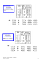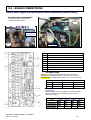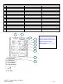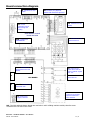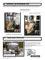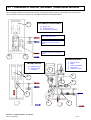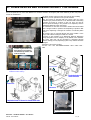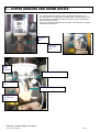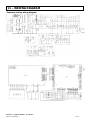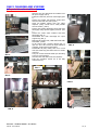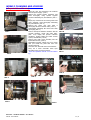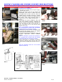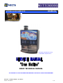
1
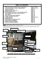
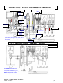
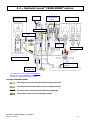
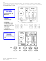
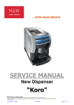
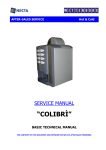
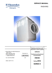
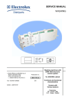
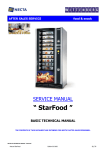
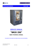
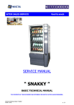
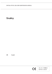
HO.RE.CA
AFTER-SALES SERVICE
This image represents the version
“ Gran Mattino espresso PLUS ”
BASIC TECHNICAL MANUAL
THE CONTENTS OF THIS DOCUMENT ARE INTENDED FOR NECTA’S AFTER SALES PERSONNEL.
NECTA SPA
TECHNICAL MANUAL “ Gran Mattino “
Manual: Gran Mattino
1 / 28
TABLE OF CONTENTS
1
2
3
4
5
5.1
5.2
6
7
8
9
10
11
12
13
14
15
Layout
Electrical systems, connections and configuration
Air-break / Espresso boilers / Instant boilers
Pumps and by-pass
Espresso coffee brewer unit
FB coffee brewer unit
Module diagram for Instant / FB / Espresso version
Doser devices and powder product containers
Doser devices
Mixer and steam suction assembly
Powder and water dose tables
Trouble-shooting
Wiring diagrams
HACCP directive (Use instructions)
Daily cleaning and hygiene
Weekly cleaning and hygiene
Monthly cleaning and hygiene
Pages 3-4-5-6
Pages 7-8-9-10
Pages 11-12-13
Page 14
Page 15
Page 15
Page 16
Page 17
Page 18
Page 19
Page 20
Pages 21-22-23
Page 24
Page 25
Page 26
Page 27
Page 28
NOTE
The above systems and functional units are specific to this machine..
All functional units installed but not listed in this document, are also used in other machines in the same range; therefore they
will be described in a separate manual for machines belonging to the same range, where all base functional units will be
described more in detail..
Opened door switch
Coffee bean
hopper
lift-up top panel for instant
products loading
6 Contenitori
solubili
Coffee grinder
and doser device
containers for
instant products
8
1
Mixer
4
Espresso coffee
brewer unit
Mixer
2
Coffee spout
holder tray
Switch disabling the
push-button panel
Ugelli mobili
Coffee
waste tray
Fustino
fondi liquidi
Spouts
holder tray
Cleaning (hygiene)
instruction sticker
Liquid waste tray
Gran mattino (Espresso coffee version): View with door open
NECTA SPA
TECHNICAL MANUAL “ Gran Mattino “
Manual: Gran Mattino
2 / 28
1 – HYDRAULIC LAYOUT “ESPRESSO” VERSION
ESPRESSO MODULE
Air-break
Open-top
boiler
BASIC MODULE
Espresso
boiler
Pump and
by-pass
Brewing unit
Mixer & spouts
Hot water
solenoid valve
Volumetric
counter
&
Waste level
microswitch
Filter
The Espresso version is fitted with two boilers, a
pressure boiler (with bypass set to 12 bar) and an
open-top boiler used for dispensing instant products
and hot water
water
solenoid valve
1.1 – Hydraulic layout “INSTANT” version
BASIC MODULE
The Instant and Fresh Brewer
versions are fitted with only one
boiler, which is the same open-top
boiler of the Espresso version
NECTA SPA
TECHNICAL MANUAL “ Gran Mattino “
Manual: Gran Mattino
3 / 28
1.2 – Hydraulic layout “ FRESH BREW ”version
Air-break
FRESH BREW MODULE
open-top boiler with
instant solenoid
valves
BASIC MODULE
“Anti-boiling”
Coffee expansion
Vessel
Hot water
solenoid valve
Mixer & Spouts
FB BREWING UNIT
level float for liquid
waste tray
water inlet
solenoid valve
The Fresh Brewer version is fitted with only one
open-top boiler with a separate air break, which is
the same as the Espresso and instant versions
COLORED ARROWS LEGEND
Cold water flow from the solenoid valve to the boiler inlet
Hot water flow from the overflow hole (or steam exhaust)
Hot water flow from the solenoid valves for dispensing
(Cold or hot) water flow for draining the boiler
NECTA SPA
TECHNICAL MANUAL “ Gran Mattino “
Manual: Gran Mattino
4 / 28
Nota :
THE FOLLOWING LAYOUTS ARE ONLY GIVEN AS AN EXAMPLE, THEY COULD CHANGE ACCORDING TO SPECIFIC MARKET
NEEDS; IF NECESSARY, REFER TO THE OFFICIAL LAYOUT SUPPLIED WITH THE MACHINE. THE MACHINE IS CONFIGURED IN
THE HOTELLERIE LAYOUT BY DEFAULT
Gran Mattino Plus LAYOUT
Italy Espresso Version
SELF SERVICE
(2 dispensing points)
It corresponds to the LX
C5/IQ model.
01- ESPRESSO
02- COFFEE WITH MILK
03- INSTANT COFFEE
04- CHOCOLATE
05- LONG ESPRESSO COFFEE
06- CAPPUCCINO
07- LONG INSTANT COFFEE
08- CHOCOLATE WITH MILK
09- MILK
10- MILK WITH COFFEE ADDED
11- MILK COFFEE
12- HOT WATER
P - PROGRAMMING
FULL JUG = FILL JUG
CROSSED OUT JUG = STOP JUG
Gran Mattino RY LAYOUT
Italy Espresso Version
HOTELLERIE
( 4 dispensing points)
It corresponds to the C4/IQ
model.
NECTA SPA
TECHNICAL MANUAL “ Gran Mattino “
Manual: Gran Mattino
5 / 28
Gran Mattino RY LAYOUT
Italy Instant Version
HOTELLERIE
( 4 dispensing points)
It corresponds to the I5/IQ
model.
Gran Mattino RY LAYOUT
Italy Instant Versione
SELF SERVICE
( 1 dispensing point)
It corresponds to the I5/IQ
model.
NECTA SPA
TECHNICAL MANUAL “ Gran Mattino “
Manual: Gran Mattino
6 / 28
2 - ELECTRICAL SYSTEMS - CONNECTIONS - CONFIGURATIONS
THE POWER SUPPLY CONNECTION
SINGLE-PHASE
CONNECTION
230 V AC 32 A 7400 W
3 x 4 mm2 CABLE
When a three-phase line is not
be available, a 230 V AC singlephase line can be used, after it
is checked to ensure that it is
adequately sized for
withstanding the required load
of 7400 W
Use the special blade 1,
supplied with the terminal box,
as a jumper.
C
SINGLE-PHASE CONNECTION
230 V AC 13 A 3150 W
3 x 1.5 mm2 CABLE
If the line is not suitable for
withstanding a load of 5850 W,
it is possible to reduce the
absorbed power to 3150 W, by
excluding one of the two
heating elements in the boiler
when making the electrical
connection.
In this case the performance of
the machine regarding hot
water output will be halved.
Use the special blade 1,
supplied with the terminal box,
as a jumper.
B
SETTING THE VOLTAGE MINIDIP
THREE-PHASE + neutral
CONNECTION
400 V 3 N AC 11.8 A 7400
W
5 x 1.5 mm2 CABLE
This connection is
advisable for a 7400 W
power supply to the
machine.
The machine is designed to operate under single-phase
230 V~ voltage and is protected by 15 A fuses on the
heating elements circuits and by 4 A on the electronic
control circuits.
A line having the following characteristics can be used
for the power supply connection:
- three-phase + neutral 400 V AC / 50 Hz
(recommended solution)
- single-phase 230 VAC / 50 Hz
The machine is supplied without power line cable;
for connection to the power grid use only cables type
H05 VV-F or H05 VV H2-F with adequate section (see
indications on the connection diagrams).
Before making the connection ensure that the ratings
correspond to those of the power grid, and more
specifically that the supply voltage rating is within the
range recommended for the connection points.
According to the safety standards in force (EN) a safety
main switch must be installed and located within easy
reach, suitable for withstanding the required peak load
and at the same time ensuring proper omnipolar
disconnection from the power grid with the opening gap
in the contacts of at least 3 mm.
The machine electrical connection must be permanent.
Therefore, adapters, multiple sockets and/or extensions
must not be used.
The electrical safety of the machine is ensured only
when it is correctly earthed according to the safety
standards in force.
This fundamental safety requirement must be duly
verified, and if in doubt the system must be carefully
tested by qualified technicians.
The power cable must be connected to the specific
terminal box located on the back panel of the machine,
ensuring correct position of the phases as indicated in
the diagrams, according to the type of connection.
A different connection, as well as not permitting correct
operation, could also cause damage to the machine.
To get the maximum heating power, it is advisable to
use (if possible) the following connection:
“A” three-phase + NEUTRAL 400 V 3N 11.8 A 5850 W
with a 5 wire cable having a section of 1.5 mm2.
Should this not be possible, solutions “B” and “C” can be
adopted but with the indicated limitations.
A
In the Espresso version with TWO boilers it is necessary
to set minidip 2 on the control board (see relevant
chapter), defining the control settings for the boiler
heating elements according to the available power and
therefore to the type of connection used.
If the connection type is the one shown in Fig. A and C
it must be set to OFF and therefore both boilers will
operate simultaneously, thus achieving maximum
output.
If the connection type is the one shown in Fig. B it must
be set to ON and therefore the boilers will alternate,
thus achieving a smaller hourly output
NOTE : The indicated power values are referred to the
Espresso version with two boilers. See the following table
for the other versions
NECTA SPA
TECHNICAL MANUAL “ Gran Mattino “
Manual: Gran Mattino
7 / 28
2.1 - BOARD CONNECTIONS
View of power supply unit and actuation board compartment (without casing)
MOTHERBOARD COMPARTMENT
1 VIEW WITH PROTECTIVE CASING
2 ) VIEW WITHOUT CASING
Fig 2
Securing screws
to be undone
Fig 1
CPU Board
REF.
3
1
2
3
4
5
6
7
8
4
5
2
•
DESCRIPTION
ESPRESSO COFFEE BOILER TRIAC
RAM
ACTUATION RELAYS K1 - K17
EPROM
Configuration Minidip
Multi-turn TRIMMER (ESPRESSO BOILER TEMPERATURE)
JUMPER
LED indicators*
LED INDICATORS
RED LED = Indicating heating of the espresso coffee boiler
GREEN LED = Blinking to indicate correct processor’s function
YELLOW LED = Indicating the presence of 12 V for board control
MODEL
MINIDIP
6
7
3
4
ESPRESSO
INSTANT
FRESH BREW
ON
OFF
OFF
OFF
OFF
ON
With minidip 1 set to OFF more selections are dispensed
simultaneously
Minidip 2 defines the control settings for the boiler heating
elements according to the available power (see power
connection at Pag. 7)
PAYMENT SYSTEM CONFIGURATION
TYPE
8
1
NECTA SPA
MINIDIP
5
MINIDIP
6
MINIDIP
7
MINIDIP
8
None
OFF
OFF
OFF
VALIDATORs
OFF
ON
OFF
OFF
VALIDATORs
WITH CREDIT
OFF
OFF
ON
OFF
OFF
TECHNICAL MANUAL “ Gran Mattino “
Manual: Gran Mattino
8 / 28
Descriptions of relay functions
Relay
ESPRESSO VERSION
INSTANT VERSION
FRESH BREW VERSION
K1
COFFEE DISPENSING SOLENOID VALVE
SOLENOID VALVE EV 5
SOLENOID VALVE EV 5
K2
COFFEE RELEASE MAGNET
ACTIVATING DOSER DEVICE 5
ACTIVATING DOSER DEVICE 5
K3
ACTIVATING COFFEE GRINDER
ACTIVATING MIXER 4
ACTIVATING MIXER 4
K4
STARTING PUMP
FREE
FREE
ACTIVATING DOSER DEVICE 4
STARTING FRESH BREW UNIT MOTOR
K6
K 5 STARTING COFFEE UNIT MOTOR
ACTIVATING MIXER 1
ACTIVATING MIXER 1
ACTIVATING MIXER 1
K7
ACTIVATING MIXER 2
ACTIVATING MIXER 2
ACTIVATING MIXER 2
K8
SOLENOID VALVE EV 4
SOLENOID VALVE EV 4
SOLENOID VALVE EV 4
SOLENOID VALVE EV 2
K 10 ACTIVATING DOSER DEVICE 3
K 11 ACTIVATING DOSER DEVICE 2
K 12 ACTIVATING DOSER DEVICE 1
SOLENOID VALVE EV 2
SOLENOID VALVE EV 2
ACTIVATING DOSER DEVICE 3
ACTIVATING DOSER DEVICE 3
ACTIVATING DOSER DEVICE 2
ACTIVATING DOSER DEVICE 2
K9
ACTIVATING DOSER DEVICE 1
ACTIVATING DOSER DEVICE 1
K 13 SOLENOID VALVE EV 1
K 14 SOLENOID VALVE EV 3
K 15 ACTIVATING CONTACTOR
SOLENOID VALVE EV 3
SOLENOID VALVE EV 3
ACTIVATING CONTACTOR
ACTIVATING CONTACTOR
K 16 ACTIVATING WATER INLET SOLENOID
K 17 ACTIVATING MIXER 3
ACTIVATING WATER INLET SOLENOID
ACTIVATING WATER INLET SOLENOID
ACTIVATING MIXER 3
ACTIVATING MIXER 3
1
SOLENOID VALVE EV 1
SOLENOID VALVE EV 1
2
PUSH-BUTTON BOARD LAYOUT
10
3
8
4
This board controls the alphanumeric
display, the selection keys and the service
keys.
It supports the payment system
connectors as well as the printer port or
other serial systems
5
9
1 - To the programmer
2 - Serial port RS232
3 - Trimmer for LCD display contrast
4 - Programming key
5 - Mixer cleaning button
6 - To the LCD display
7 - To push-button panel
8 - To the front validator
NECTA SPA
6
7
TECHNICAL MANUAL “ Gran Mattino “
Manual: Gran Mattino
9 / 28
Board connection diagram
J4 Connector for Door
switch
J7
RS 232
connection port for
data storing and
reading
J9 Connector for payment
system with Executive protocol
J2 connector for LCD
display
Push-button control
board and LCD
J10
J6 Connector for the
selection buttons
Connector for
PROGRAMMER
J4 -J5 Connector for
push-button board and
display
J6
J7
CPU BOARD
J2 Connector for
water failure and full
waste container signals
IVA - IPF
J2 Connector for bulb
thermostat TH
J6 –J7 Connector for
functional units
J3
J1 Board power
supply connector
Connector for Instant,
Espresso and FreshBrew modules
NB : The CPU and push-button boards are used also in other vending machine models; therefore some
connectors are not used in this model
NECTA SPA
TECHNICAL MANUAL “ Gran Mattino “
Manual: Gran Mattino
10 / 28
3 – Air-break & Boilers
The main function of the air-break is to keep the water level constant and to signal a water flow interruption from the mains;
in the event of such water failure the current selection can be completed.
In addition, it serves the purpose of holding a reservoir of water at normal atmospheric pressure, so that the pump can draw
the correct water dose for the selection and deliver it to the Espresso boiler without changes in pressure that may affect the
volumetric counter reading.
The GRAN MATTINO vending machine is equipped with an air-break separate from the boiler, because of the need to have
cold water for the Espresso pressure boiler.
The air-break is the same type used for the Zenith and other models, therefore it’s a highly reliable and accurate functional unit.
In order to standardise construction it was installed in all three versions: Instant, Espresso, Fresh-Brew.
The water dose used for the selections is measured by means of the volumetric counter for the Espresso coffee selections,
while it is measured by timing the solenoid valve opening (in tenths of a second).
The water level is ensured by a float that triggers a microswitch, keeping the level between a factory set minimum and
maximum (it very important not to replace the microswitch with any one of different mechanical characteristics, as a variety of
malfunctions may occur).
Furthermore, in the event of failure to the maximum level microswitch, an overflow hole allows the water to be conveyed
through a tube and to the safety device fitted on the water inlet solenoid valve, thus causing its mechanical lock (such safety
device is triggered also in the event of a power failure).
The air-break also causes a signal to be sent the machine control board necessary for the initial installation and for filling with
water, that anyway need to be done manually.
If upon switching the machine on the float does not trigger the maximum level microswitch within a set time (e.g. 60 sec) the
vending machine locks due to a water failure.
View of compartment showing the air-break without protective casing
Float +
microswitch
Open-top boiler
Air break
Water inlet
Gravity solenoid
valve
NECTA SPA
TECHNICAL MANUAL “ Gran Mattino “
Manual: Gran Mattino
11 / 28
3.1 - PRESSURE BOILERS
The GRAN MATTINO Model has THREE versions with two different configurations; an Espresso version fitted
with the Espresso pressure boiler for Espresso products and an open-top boiler for Instant products, an Instant
version fitted with only one open-top boiler and separate air-break. And a FRESH BREW version also fitted with the
open-top instant boiler.
The espresso boiler is the same used for other models with higher capacity, therefore with the same well-known and
established characteristics and reliability, but with specific application for such vending machine.
The open-top boiler for the Instant and FB version is a new design and specific for such model.
Three-way
solenoid valve
for coffee
Earth cable
connection
safety
thermostat
Temperature
probe
SCHEMA FUNZIONAMENTO CALDAIA IN PRESSIONE
Pressure
boiler
SONDA NTC
REAR COMPARTMENT WITHOUT PROTECTIVE
CASING
See relevant functional unit manual for details, photos and
complete description
The internal temperature control in the espresso boiler is by means
of an NTC type electronic probe fitted with an internal 12 kohm (±
ohm) resistance at a temperature of 25° C.
As the temperature increases the resistance is reduced
progressively as indicated in the following table.
Pump &
by-pass
TERMOSTATO
CALDAIA
Counter inlet
water filter
Boiler temperature °C
Value in ohm
Allowed tolerance
0
25
50
85
90
100
35875
12000
2900
1475
1260
963
± 7 ohm
± 4 ohm
NECTA SPA
Volumetric
counter
,,
,,
,,
,,
TECHNICAL MANUAL “ Gran Mattino “
Manual: Gran Mattino
12 / 28
3.2 – OPEN-TOP BOILER
open-top boiler
AIR-BREAK
IMMERSED BULB
THERMOSTAT
View of internal compartment without containers
but with protective casing
View of internal compartment without protective
STEAM OUTLET
HOLE
FLOW ADJUSTMENT SCREW
Anti-boiling
thermostat
GRAVITY SOLENOID VALVE DETAIL
DETAIL of Anti-boiling
thermostat position
SAFETY DEVICES
The boiler is fitted with electric safety protections against dry operation
overheating and boiling caused by a failure to the temperature control
system.
In the event of dry operation overheating the bulb thermostat acts as a
hardware safety system and disconnects the power supply from the heating
elements.
In the event of overheating with the boiler full of water, the steam is forced
to exit from the overflow hole and, flowing through the copper pipe, trips the
thermostats (one for each phase) that then disable the power supply to the
heating elements.
Set must be manual after checking and fixing the problem.
The boiler used in the Gran Mattino model is of the open-top type (i.e. with an external opening that will ensure that the
internal pressure does not exceed the atmospheric pressure). It is fitted with two 230 V AC heating elements, 2700 W each.
In the situation of maximum output, a total power of 5400 W is absorbed (when two heating elements are operating).
The water level is ensured by the separate air-break through a communicating vessels connection.
Contrary to the Piccolo Mattino model (where the level control is by means of probes) in the Gran Mattino the Air-break solution
has been adopted because of the need to have cold water for the espresso module; such solution has been adopted also in the
other Instant and Fresh-brew versions to standardise the models and circuits.
The overflow level is ensured by both the air-break and an overflow hole that also serves the purpose of controlling the antiboiling system.
Should there be any hot water or steam flow out of such hole because of a malfunction the two klixons (manually resettable)
are triggered, stopping the function and locking the machine.
SEE FUNCTIONAL UNIT MANUAL REGARDING BOILERS FOR DETAILS, FUNCTIONS AND SAFETY DEVICES
NECTA SPA
TECHNICAL MANUAL “ Gran Mattino “
Manual: Gran Mattino
13 / 28
4 - PUMP AND BY-PASS
In order to supply water to the espresso boiler, only for the
ESPRESSO version, the same vibration pump used in the entire
range of espresso machines is used.
Of course the application is different, as pump, boiler and
connections are positioned inside a compartment accessed from the
rear after removing the back panel.
This solution ensures total full access for maintenance and hygiene
(see picture).
The pump has overheating protection in case of continuous or dry
operation by means of a 90° C self-resetting klixon, fitted to the
power supply unit as standard feature.
To be pointed out the klixon was sized not to be triggered at all in
normal vending conditions; however, in the case of continuous power
supply caused by any malfunction, or operation without water, the
klixon will be triggered at the pre-set temperature to prevent
overheating that is dangerous to the pump coil.
The by-pass is factory pre-set at 12 bar.
The pump is activated by relay K 4
By- pass
Vibration
pump
Check-valve
(Non-return)
VIEW OF PUMP - BOILER ( without back casing )
EXPLODED VIEW HYDRAULIC
SYSTEM FOR ESPRESSO BOILER
3-way solenoid
valve
safety
thermostat
NTC Probe
temp. controller
Resistance
By-pass
Check-valve
(Non-return)
Check-valve
(Non-return)
Vibration
pump
Water filter
volumetric
counter
NECTA SPA
TECHNICAL MANUAL “ Gran Mattino “
Manual: Gran Mattino
14 / 28
5 – ESPRESSO COFFEE BREWER UNIT
The well-known and reliable Z 2000 M unit is used, but with some changes to make it more suitable and with
simpler operation, to take into account the high range characteristics of the GRAN MATTINO vending machines.
Espresso coffee brewer detail
Positioned at the upper dead centre
Ready for loading ground coffee
The unit is factory fitted for the
installation of a first coffee heater kit
BREWER UNIT IN OPERATING POSITION
5.1 – FRESH-BREW COFFEE UNIT
This is a specific version fitted with the Fresh-brew coffee
unit.
Such unit for the moment makes filtered coffee using
special coffee for FB, already ground to a coarser grade
compared to espresso coffee. Such coffee is consumed
especial in northern European countries.
This is a modern, very compact unit. For further details see
the functional unit manual.
FRESH BREW COFFEE UNIT
REMOVED FROM THE MACHINE
Positioning FB unit
NECTA SPA
TECHNICAL MANUAL “ Gran Mattino “
Manual: Gran Mattino
15 / 28
5.2 – DIAGRAMS OF INSTANT/ESPRESSO /FRESH BREW MODULES
The Gran Mattino machine has three different versions using the same hydraulic system, with the difference concerning the
water connection of the three modules used. The different connections are illustrated below.
FRESH BREW COFFEE MODULE
3
1) Brewer unit
2) Expansion vessel
3) Ground coffee container
Hot water flowing from the solenoid
valve on the instant boiler
Cold water draining from the air-break
and water system (communicating
vessels)
Fresh-brew coffee flow to dispensing
spouts
1
2
ESPRESSO MODULE
INSTANT MODULE
4) Additional mixer
5) Instant product
3
containers
1)
2)
3)
4)
5)
Espresso boiler
Pump
Coffee bean hopper
Brewer unit
Volumetric counter
1
2
2
1
4
NECTA SPA
5
TECHNICAL MANUAL “ Gran Mattino “
Manual: Gran Mattino
16 / 28
6 - DOSER DEVICES AND POWDER PRODUCT CONTAINERS
Due to the particular use of the Gran Mattino new solutions needed to be designed, with easier fastening to allow easy and full
access for maintenance
The doser devices evolve from the ones used in other vending
machines, but are optimised for the specific function.
They are secured to the back with two screws, they are of the
induction type powered with 230 V AC and fitted with overheating
An upper-hinged lid is
protection by means of a klixon on the coil. They are used at
provided to gain access
different
speed according to the product to be dispensed, and are
to the containers.
identified by different colour drive gears.
The containers are the same ones used in the Brio and can be fitted
with a whipper inside to optimise the dispensing of products that
form clots; dispensing is through the rotation of food-safe plastic
augers.
The powder dose is metered through the timed rotation of the
auger, with software settings in tenths of a second.
According to the products to be dispensed, different dispensing
timing and phases can be adopted, set by default in the software.
The motor start time can be increased or decreased through
software setting, but any dispensing cycles set by default cannot be
changed.
Activation is by means of relays:
K5 -K10 – K11 – K12 FOR DOSER DEVICES – MD3 – MD2 – MD1 MD4
In order to gain access to the
doser devices, all containers
and the boiler protective wall
must be removed.
Screw feeder
Auger clutch and drive gears (the different colour indicates
a different rotation velocity)
Exploded view of
doser devices
ratiomotor
ratiomotor
tt
Exploded view of doser for fresh brew unit
Container with scraper
NECTA SPA
TECHNICAL MANUAL “ Gran Mattino “
Manual: Gran Mattino
17 / 28
7 – COFFEE GRINDER AND DOSER DEVICE
The espresso version is equipped with a coffee grinder and doser unit.
The same grinder and doser unit of the Spazio/ Brio / Venezia range is used.
The only change is the different coffee bean hopper, which has cylindrical
shape and greater capacity.
1200 g
Refer to the specific the functional unit manual for all maintenance, cleaning
Innesti dentati
contenitori / motoriduttori
capacity
and adjustment operations.
coffee
hopper
Grinding
adjustment
knob
Coffee dose
adjustment
lever
Coffee
hopper
release lever
Grinding adjustment knob
Release magnet
coil
Coffee dose microswitch
pre-set ground coffee
dose adjustment
lever
NECTA SPA
TECHNICAL MANUAL “ Gran Mattino “
Manual: Gran Mattino
18 / 28
8 – MIXER AND STEAM SUCTION ASSEMBLY
Mixer being removed
for cleaning
Detail of motors viewed with wall lifted
Mixer detail
(Version with integrated drawer)
Apart from their application, the mixers are the usual excellent and reliable ones used in the entire
Necta production. A mixer must have two important features:
1) Ease of disassembly and limited number of components
2) The aspect and blend quality of dispensed products must be as much as possible like the
products served at a bar.
The motors are high rotation speed type fitted with radio interference suppressors and self-resetting
overheat protections.
The motors are activated by relays k3 – k5 – k6 – k7- K17 for motors MF 5 – MF4 – MF1 – MF2 –
MF3 (this applies to the instant version).
Relays K3 and K5 (which have other functions) are not used in the espresso version.
The steam exhaust and powder removal system reflects all the systems already used by Necta. A
kind depression is created in compartment “A” by means of a cross-flow fan; such depression sucks
the steam that forms during mixing, at the same time fine dust is inadvertently sucked and therefore
must be removed before the hot air is expelled through the rear grille. The powder drawers fill up at
each selection; therefore they must be emptied and sanitised (see specific manuals).
View of steam suction A
compartment without upper casing
Powder removal
drawer being
extracted for
emptying
NECTA SPA
TECHNICAL MANUAL “ Gran Mattino “
Manual: Gran Mattino
19 / 28
9 – POWDER AND LIQUID DOSE TABLES
Factory “default” settings (doses for ITALY)
Water dose Powder dose
Selection code
d/s.
Coffee
CA1
Not used
CA2
Long coffee
CA3
Coffee with milk
CA4
Cappuccino
CA5
Milk
for
Coffee with milk
LA1
LA2 Milk for cappuccino
Milk for cap choc.
LA3
Milk
for Chocolate
LA4
Coffee for cap choc
KA1
Chocolate
for cap choc.
KA2
Milk
for tea
KA3
Chocolate
KK1
Strong
Chocolate
KK2
Milk Chocolate
KK3
Thè nature
TE1
Thè
nature + milk
TE2
decaffeinated coffee
DE1
Not used
DE2
Broth
BR1
Hot water
AC1
½ Jug of coffee
PC1
½ Jug of milk
PL1
PK1 ½ Jug of Hot chocolate
½ Caraffe Tea
PTI
½
Caraffe Water
PA1
½ Caraffe
PD1
PC2
PL2
PK2
PT2
PA2
PD2
NECTA SPA
decaffeinated coffee
Jug of coffee
Caraffe Milk
Caraffe Chocolate
Caraffe Tea
Caraffe Water
Caraffe
decaffeinated coffee
cc d/s.
gr.
23
0
35
23
23
16
35
25
19
23
14
40
0
60
40
40
25
55
40
30
40
25
20
0
20
20
20
10
19
19
15
20
6
1,2
0
1,2
1,2
1,2
2
4
4
3
1,2
3,5
19
30
10
2
50
50
33
90
90
60
33
42
25
21
24
16
57
100
4
0,5
37
70
4
0.5
23
40
20
1,2
0
0
0
0
0
0
0
0
33
160
250
160
160
167
160
100
400
400
400
400
500
400
0
97
185
145
20
0
97
0
6
40
80
2,5
0
6
325
500
325
325
340
325
800
800
800
800
1000
800
193
370
290
40
0
193
12
80
160
5
0
12
Water selection doses
Coffee
Long coffee
Decaffeinated coffee
Coffee with milk
cappuccino
cappuccino Chocolate
Chocolate
Strong Chocolate
Chocolate with milk
Tea
Tea with milk
Hot water
TECHNICAL MANUAL “ Gran Mattino “
Manual: Gran Mattino
20 / 28
10 – TROUBLE-SHOOTING
Problem
Possible cause
Solution
No water flow from the mains or
insufficient pressure (5-85 N/cm2)
The air-break microswitch is faulty
Water inlet solenoid valve locked
by the overflow tube and activated
by the relevant relay
Check for the presence of one or more of the situations
indicated and once identifying the cause do as follows:
Short-circuit the microswitch to check it’s functioning
Unlock the water inlet valve, undoing the threaded ring and
emptying the overflow tube
Check for 230 V AC voltage at the solenoid valve power supply
ends
Check the activation of relay K 16
(And/or indication on the display)
The machine does not go
into the boiler heating
phase, remaining in the
“installation” phase
The grinder motor is locked
The display indicates the because there is no coffee or
because the relay was not tripped.
message
There is no coffee
“No coffee”
The grinder wheels are locked
(ONLY for the espresso
because of foreign matter in the
version.)
coffee
Grinder motor overheating device
triggered
The coffee container shutter was
not opened.
The display indicates the Failure to the release magnet
Failure to the coffee dose
message
“Coffee release failure” microswitch
Failure to relay K 03
The display indicates the
message
“Boiler failure”
or
“Instant boiler failure”
The Espresso version is equipped
with two boilers, a pressure boiler
and an open-top boiler
(Therefore both must be checked).
The boiler does not heat
Dry operation protection system
triggered.
Anti-boiling protection system
triggered. (for instant boiler)
The contactor does not activate
the instant boiler heating elements
When an espresso coffee selection is made the grinder is
activated conveying coffee to the doser device, the motor lock
is determined by the microswitch, which is triggered when the
set dose is reached. If such microswitch is not triggered, the
system disables all espresso coffee selections, indicating the
message “No coffee” on the display, once identifying the
cause:
Check the wear of the brushes
Free the grinder wheels with the utmost care (Disconnect the
power),as blocked wheels could have triggered the overheating
protection, which is reset-able. Open the shutter, add coffee
Check for the activation of relays K3 – K16
After grinding and during the attempt of releasing the ground
coffee, the doser device plate triggers a microswitch that
signals the coffee release
If such microswitch is not triggered, there could have been two
causes:
Failure to the release magnet or overheating protection
triggered (resetting is automatic, and after approximately 5
minutes it is reactivated, but the cause of such trigger must be
identified).
Failure to the microswitch: replace with an identical one
designed for the GM, in the event of using a microswitch with
different characteristics considerable discrepancies in the
ground coffee doses may occur.
The machine is locked if after 10 minutes heating the set
temperature is not reached (The time for the instant boiler is
set to 120 minutes).
Check for the correct operation of the heating element, the
thermostat, the probe, the actuation TRIAC and contactor for
activating the instant boiler
In the event of replacing the probe(Espresso boiler) the correct
temperature must be re-adjusted using the trimmer.
In the instant version, check also the over-boiling thermostat
and if triggered identify its cause
Check that the water supply from the mains is operating.
The display indicates the The water inlet solenoid valve
remains energised for 30 sec (or 4 Check that the water inlet solenoid valve is working properly
message
minutes after the machine is
and relay K16 is activated
“WATER FAILURE”
switched on); during this time the Check that the air-break is functioning correctly.
air-break float’s microswitch must Check that the water inlet solenoid valve is not mechanically
be activated; if this does not occur blocked by the overflow membrane
and if there are no problems in the
water supply from the mains,
check the points in the next
column
NECTA SPA
TECHNICAL MANUAL “ Gran Mattino “
Manual: Gran Mattino
21 / 28
The display indicates the
message
“Espresso unit”
FB coffee unit failure
The espresso unit failed to
reposition.
Failure to the lower dead centre
positioning microswitch.
Failure to relay K05
Overheating device triggered
The display indicates the
The set liquid dose is not reached
message
within 60 sec. (The volumetric
“Volumetric counter”
counter in the GM espresso model)
(flow-meter)
ONLY for the espresso
version
In the instant version the water
dose is determined by timed
solenoid valve opening via SW
Check for the correct operation of the lower dead centre
positioning microswitch.
Check that the unit stops correctly at the upper dead centre
(monitored via SW). If not replace the board or reprogram
the CPU
Check for the overheating protection trigger and check the
cause
The water amount for the espresso coffee selections is ensured
by a volumetric counter; with the water flow a wheel rotates
and through sensors sends a number of pulses corresponding
to the water dose programmed in the SW. If such dose is not
reached within 60 sec. it means that there is a problem:
Check for the correct functioning of the volumetric counter;
there must be 5 V AC on the terminals during the counter
operation.
Check that coffee is not ground too fine and the dose
excessive.
Check for clogging in the coffee filters
No water from the mains.
If in the period taken to make 6 selections with any dose the
microswitch controlled by the air-break float is not triggered
The vending machine is locked for air-break failure.
The malfunction could occur for lack of water from the mains,
In the instant version the air-break or because of a failure to the float microswitch system.
is incorporated in the open-top
Replace the microswitch with one having the same
boiler.
characteristics, otherwise other malfunctions may occur.
The display indicates the Faulty air-break microswitch
Failure to the float actuation
message
Microswitch system.
“Air-break failure”
The display indicates the Wrong RAM data, which must be Enter into the installation procedure and initialise the software;
retrieved by initialising the EPROM. if the failure persists replace the CPU or reprogram the Flash
message
There may be various causes,
EPROM.
“ RAM data”
including possible electromagnetic
interference above the norm.
The display indicates the If the coin mechanism is fitted, it Check the correct software setting of the payment system
communicates with the CPU by
used.
message
means
of
signals
that
last
less
Connect a functioning coin mechanism to see if the failure is
“COIN MECH FAILURE”
than two seconds (validators)
or communication the is no
communication for more than 30
sec (serial systems)
If the coin mechanism is not
fitted, check the software setting
reset.
Check that the connection is correct.
Initialise the software
Otherwise, replace the CPU
The coffee lacks body and Excessively coarse grinding.
cream and is dispensed Insufficient ground coffee dose.
too quickly
Inspect the grade of grinding, keeping in mind that it takes
between 15 and 20 seconds to dispense optimum espresso
coffee.
A shorter time means that the grade of grinding is too coarse.
With wear the grinding wheels must be adjusted regularly.
After 50,000 cycles, if necessary replace
Check the coffee dose, weighing it at least for 5 consecutive
doses; the average weight must be between 6.5 and 7 grams.
Coffee is dispensed too Excessive coffee dose.
slowly and it tastes burnt Grinding too fine.
Inspect the grade of grinding, keeping in mind that it takes
between 15 and 20 seconds to dispense optimum espresso
coffee.
A longer time means that the grade of grinding is too fine.
Adjust the grinding wheels.
Check the coffee dose, weighing it at least for 5 consecutive
doses; the average weight must be between 6.5 and 7 grams.
The by-pass is set from the factory to trigger at 12 bars.
Lower settings will lengthen the dispensing time and make less
cream.
Replace the coffee filters, replace the solenoid valves.
Faulty pump by-pass.
Clogged coffee filters.
Scale deposits in the solenoid
valves
The mixers
“clog up”
The display indicates the
message
“Waste full”
NECTA SPA
The whipper failed to rotate.
Powder removal drawer full.
Insufficient water to powder ratio.
Error in the dispensing cycles, set
by default
Check for the motor overheating protection trigger, if necessary
check the cause of such trigger.
Empty the powder removal drawer.
Check / adjust the water to powder ratio.
Check the logic of the cycles.
Inside the tray there is a float
Check that it is full and empty it; check that the microswitch
that triggers a microswitch when works correctly
the programmed level is reached. Check that the tray is inserted correctly.
TECHNICAL MANUAL “ Gran Mattino “
Manual: Gran Mattino
22 / 28
The level control device
does not detect the
presence of water and
the boiler overflows,
triggering the
mechanical lock of the
water inlet solenoid
valve
The level control is managed directly
in the boiler the following way:
A probe made of special conductive
material is immersed in the water,
resulting in an extra-low voltage
electrical conduction between the
probe and the water in the boiler. If
the water level drops the probe is no
longer covered and there is no
conduction.
An electronic control unit separate
from the CPU, processes this signal
sending the information to the CPU
that activates or deactivates the
triggering relay of the water inlet
solenoid valve.
Check the level control system, composed of a probe and control
unit. Check the CPU functioning. Check the mains water hardness
(if too low, therefore below the level indicated by the current
regulations regarding natural spring water, proceed to correct the
salt content).
Check that the probe does not have scale deposits that could
hinder the correct transmission of signals.
The display indicates the The procedure disabling the buttons Access programming and disable suck lock, or reset the lock
caused by the maximum number of selections reached, or disable
may have been activated.
message
it. If the problem persists, initialise the Eprom.
Or the maximum number of
"Suspended service"
previously set dispensed selection
may have been reached.
The coffee lacks body and
cream.
The products are perfectly
mixed and contain large
“un-dissolved” clots
The mixers do not rotate.
The coffee dose is insufficient.
The cycle timing is not correct.
Note: some instant products are
dispensed by the doser device in
“step” mode, i.e. with ON and OFF
phases, to ensure correct dissolving.
Check the correct operation of the mixers.
Check that the relay is activating the motors.
Check that the motor overheating protections were not triggered.
In the preset layouts, precise positions were identified for some
selections, with operating times and cycle timing appropriately studied.
In the event such layout was changed, dispensing may not occur
correctly.
Restore the correct layout.
The dispensed products
have inadequate
temperature
“Too Cold”
According to the product type an
optimum temperature is set by
default.
In any case, it must not be lower than
70° C
Should that occur, the thermostat may
be adjusted incorrectly, or in the case
of the espresso version check the
probe.
Check the correct setting of the thermostat, factory set to 80° C (± 2°
C).
Check the dispensing temperature with a digital immersion
thermometer in at least 10 consecutive selections.
The average for the 10 selections must be between 70° and 80° C;
different values indicate incorrect setting.
Values too low may indicate that the thermostat is faulty or that the
heating elements are not activated properly.
The optimum temperatures are
indicated in the previous paragraph.
If the anti-boiling control is
triggered, the problem is due to the
thermostat set too high or to a
short-circuit, or to a faulty probe;
with no level control the water
overflows, and being hot it triggers
the anti-boiling control.
Check that the thermostat is triggered at a temperature of 80° C
using a digital tester connected to its terminals.
Too high temperatures, e.g. 90-95° C, considering the thermal
differential of a thermostat, could create temporary steam
conditions that would trigger a sensitive anti-boiling thermostat.
If the thermostat works correctly, check level control probe that
must trigger the solenoid valve lock when immersed in water.
The dispensed products
have excessive
temperature and
occasionally the “antiboiling” control is
triggered
Check for the motor overheat protection trigger, if necessary
check the cause of such trigger.
Empty the powder removal drawer.
Error in the dispensing cycle timing, Check / adjust the water to powder ratio.
Check the logic of the cycles, also checking that the layout is
set by default.
correct.
The mixers “clog up“ and The whipper failed to rotate.
the product overflow from Powder removal drawer full.
Insufficient water to powder ratio.
the funnel
The powder is not
dispensed and the drink is
composed of only “hot
water”
The powder is dispensed by the
rotation of the doser devices for a
certain time set in tenths of a
second.
The doser devices are protected
from overheating by means of a
Klixon.
The thermal protection Klixon in the doser devices was triggered.
Approximately ten seconds are necessary for its reset. In the event
of triggering, the cause must be identified anyway, as it is sized for
normal operation and its triggering indicates that there is a
malfunction to be corrected. Check that the instant products are
not “clogged” by humidity.
In spite of having correct
dose settings the liquid
amount is “insufficient”
or “excessive”
The liquid amount is determined
by the timed opening of the
solenoid valve, expressed in tenths
of a second and set via software.
The solenoid valves are factory set
with an optimum flow rate.
The solenoid valves are factory set with an optimum flow rate;
the dose is metered by their opening in tenths of a second, and
this combined with the flow rate determines the correct liquid
amount. After continuous use, scale deposits may form in the
valves, resulting in a reduced flow rate. De-scale the solenoid
valves; it is not advisable to change the dispensing time, the
correct flow rate must be restored instead.
On the contrary the solenoid valve ate too “open”; keeping
unchanged the software dose settings close the valves as
necessary to achieve the correct doses.
NECTA SPA
TECHNICAL MANUAL “ Gran Mattino “
Manual: Gran Mattino
23 / 28
11 – WIRING DIAGRAM
Espresso version wiring diagram
NECTA SPA
TECHNICAL MANUAL “ Gran Mattino “
Manual: Gran Mattino
24 / 28
HACCP DIRECTIVE (EEC 93/43 and 96/3)
Outline and instructions for use
Notes: What is indicated by the EEc Directive 93/43 96/3
Directives EEC 93/43 and 96/3 concern the hygiene of food products and are based on the HACCP (Hazard
Analysis Critical Control Point).
The purpose of this directive is to safeguard the consumer health, suggesting a series of actions to be taken by the
vending company, aimed at checking, identifying and correcting any critical aspects in the foodstuff chain, from the
purchase of products and machines to the dispensing of the product.
The HACCP is a system used to analyse any potential risks in the manufacturing and distribution cycle of food
product and to identify critical points where such risks can occur; the system also highlights the actions to be
undertaken and the decisions to be made with regard to such critical points, as well as the implementation of
checking and monitoring procedures.
Therefore, each vending company must develop a Company Hygiene Self-control Manual according to the
provisions of the directive - and if necessary use the information and recommendations formulated by some
associations in the sector. The manual must contain a programming and checking schedule for the vending
machine hygiene condition.
Important notes:
For correct use of the machine, the directives must be fully applied. The operator is responsible for
correct operations on a vending machine, as indicated in the self-control manual.
HACCP Directives (EEC 93/43 and 96/3)
Guidelines for correct application
Ensure hygiene control with a special manual for correct hygiene practices.
After cleaning, do not touch the surface of any elements that may come into contact with food.
Wash your hands thoroughly, preferably using disinfectant, before starting any hygiene operations
Use disposable sterile gloves
Always use a clean cloth to wipe dry.
Keep the work area tidy.
Check that the product packages are intact and not damaged.
Keep coffee and powder products in a cool, dark and dry place.
Use products within the recommended time period (see expiry date on the package).
Always use products from the warehouse according to the principle of “first-in first-out”.
Tightly close and seal any product packages not completely used, then ensure that they are used as soon as possible.
Coffee and consumables must be kept and transported separate from the cleaning products.
The product containers must be cleaned regularly (see operation instructions).
Only fill coffee or other product containers with sufficient amount for the expected use until the next
cleaning.
In the case of products classified as Food (therefore to be kept at a well defined temperature, normally under 4°C)
such products must be conserved, transported and stored in special suitable equipment that are capable of
maintaining the cold chain at the correct temperature.
Do not replace original components that are in contact with foodstuff with other third party purchased non-original
parts that are not certified as being food-safe (the food-safe certification is ensured by the special symbol stamped on
the components and by a written certificate issued by the manufactured or other authorised body)
Cleaning the machine (Page 26,27,28 )
Carefully observe the cleaning instructions as described in the following pages! and carry out cleaning within the terms
indicated
Clean the machine, preferably at the end of the day or in the morning before the machine is used.
After cleaning, dispense and check a drink (see last check).
Fill in the check list log for cleaning operations , including the date and operator’s signature
When the display indicates an error message immediately check the trouble-shooting sheet.
Use only recommended cleaning products approved for foodstuff, preferably liquid; avoid the use of powder and
abrasive products.
NECTA SPA
TECHNICAL MANUAL “ Gran Mattino “
Manual: Gran Mattino
25 / 28
DAILY CLEANING AND HYGIENE
( Expected time 8 min. 30 sec)
Open the door and disconnect the machine form
the power supply. (FIG 1)
Empty the waste tray and rinse it thoroughly (FIG
2)
Remove the powder trap drawers, empty them
and rinse them with hot water (FIG 3)
Clean all grinding residue from the coffee
dispenser (using a brush and a small portable
vacuum cleaner) ( FIG 4)
Remove the powder dispensing spouts and clean
thoroughly using specific hygiene products. (FIG
5)
Remove the coffee waste container and clean
thoroughly (FIG. 6)
Disassemble and clean thoroughly the spout
support tray (FIG. 7)
FIG. 1
Remove the coffee unit, clean and rinse with
hot water. (FIG 8 )
In the version with a support cabinet (FIG. 9)
open the door and remove the liquid collection
container, empty and rinse thoroughly.
Reassemble all parts, taking care not to touch
with your hands any parts that come into contact
with food.
Carry out a mixer automatic wash cycle according
to the pre-set procedures.
Close the door and make some test selections.
Enter the operations carried out in the daily
maintenance log.
FIG. 2
FIG. 9
FIG. 7
FIG. 3
FIG. 8
FIG. 4
NECTA SPA
FIG. 5
FIG. 6
TECHNICAL MANUAL “ Gran Mattino “
Manual: Gran Mattino
26 / 28
WEEKLY CLEANING AND HYGIENE
( Expected time 12 min. )
Open the door and disconnect the machine
form the power supply. ( FIG 1 )
Remove the Instant powder containers and
clean thoroughly using specific hygiene
products eliminating any incrustations. (FIG.2 3)
Empty any residue from the coffee grinder and
doser assembly, clean thoroughly eliminating
any incrustations.( FIG. 4 )
Remove the coffee unit, then clean it
thoroughly and rinse with hot water ( FIG. 5 )
Disassemble completely the mixers and clean
thoroughly (FIG. 6 )
Remove the liquid collection container and the
grounds container, empty and clean them.
(FIG. 7–10) Empty the powder collection
containers, located within the steam suction
system, and disinfect ( FIG.8 ).
Remove and clean spout assembly and the
liquid collection tray ( FIG 9).
Reassemble all parts, taking care not to touch
with your hands any parts that come into
contact with food.
Close the door and make some test selections.
Carry out a mixer automatic wash cycle
according to the pre-set procedures.
Enter the operations carried out in the HACCP
log.
FIG. 1
FIG .2
FIG .10
FIG .9
FIG .8
FIG .6
FIG .3
FIG .7
FIG .4
FIG .5
NECTA SPA
TECHNICAL MANUAL “ Gran Mattino “
Manual: Gran Mattino
27 / 28
MONTHLY CLEANING AND HYGIENE (OR EVERY 5000 SELECTIONS)
Expected time 18 min. (in addition to the time taken for regenerating the filter)
In addition to the weekly operations, also the
following must be carried out:
Disconnect the machine form the power supply,
open the door ( FIG 1 )
Remove the brewer unit from the machine and
disassemble, then clean all residue and rinse
thoroughly with hot water, check the filters for
clogging and if necessary de-scale or replace
them. Reassemble all parts and slightly lubricate
the piston o-rings using food-safe grease or
replace them if even slightly damaged (FIG. 1 FIG. 2)
Disassemble the mixers completely, clean and
wash using sanitising products, especially the
powder removal area, disassemble completely the
rotor and check the state of the seal (Fig. 7),
when reassembling do not touch with the bare
hands ( FIG. 5-7-8)
Note : it is advisable to perform this operation at
the workshop and use mixers that were already
sanitised with the 'come-and-go' method
Regenerate the water softener (if installed) using
the special salt solution, even if the softener
efficiency test is still positive.(FIG. 3)
The softener filter can be contaminated easily and
therefore
regeneration
ensures
maximum
hygiene.
Note: it is advisable to perform this operation at
the workshop and use filters that were already
regenerated with the 'come-and-go' method
During regeneration, it is advisable to completely
sanitise the hydraulic system and the water inlet
solenoid valves, including the air-break. (FIG. 4-56)
FIG .1
FIG .2
FIG .8
FIG .7
Enter the operations carried out in the HACCP
hygiene program log
FIG .6
FIG .3
FIG .5
FIG .4
NECTA SPA
TECHNICAL MANUAL “ Gran Mattino “
Manual: Gran Mattino
28 / 28