1
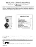
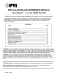
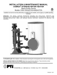
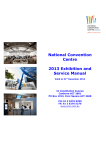
INSTALLATION & MAINTENANCE MANUAL
EZ PLATE® INSTANTANEOUS
WATER HEATER
Installation and service must be performed by a qualified service installer or service agency.
IMPORTANT: THIS MANUAL CONTAINS INFORMATION REQUIRED FOR INSTALLATION, OPERATION AND
MAINTENANCE OF THIS EQUIPMENT. READ AND FOLLOW THE INFORMATION IN THIS MANUAL AND ALL OTHER
PROVIDED INSTRUCTIONS, LABELS AND MARKINGS BEFORE INSTALLING, OPERATING OR SERVICING THIS
EQUIPMENT.
Typical EZ Plate Construction
TO THE INSTALLER: After installation, these instructions must be given to the equipment user or left near the appliance.
SPECIAL INSTRUCTIONS TO THE OWNER: Retain this manual for future reference. These instructions contain
important information that will help you in maintaining and operating this appliance.
PVI INDUSTRIES, LLC - Fort Worth, Texas 76111 - Web www.pvi.com - Phone 1-800-433-5654
PV500-63 12/14
EZ PLATE WATER HEATERS
TABLE OF CONTENTS
1.
Safety Considerations
2.
Water Heater Installation
3.
4.
2.1
Codes
2.2
Electrical Requirements
2.3
Checking Equipment Before you Install
2.4
Service Clearances
General Piping Guidelines
3.1
Water Inlet / Outlet Connections
3.2
Boiler Water Connections
Operating And Safety Controls
4.1
High Water Temperature Limit Control
4.2
Temperature Control Valve
4.3
Relief Valve Piping
5.
Description of Operation
6.
Startup Procedure
6.1
7.
Pre-startup Inspection
6.2
With All Product Valves Closed
6.3
Operating Reminders
6.4
Shut Down
Maintenance
7.1
Maintenance and Cleaning the Plate Heat Exchanger
7.2
Temperature Control Valve
7.3
Relief Valves
7.4
Y-strainers
8.
Troubleshooting Suggestions
9.
Standard EZ Plate Wiring
Warranty forms ship separately with each product.
2
PV500-63 12/14
EZ PLATE WATER HEATERS
1
SAFETY CONSIDERATIONS
WARNING: Do not use this appliance if any part has been under water. Immediately call a qualified service
technician to inspect the unit and to replace any part of the control system and any other items affecting safe
appliance operation and which has been under water. Failure to follow these instructions can cause property
damage, personal injury, or exposure to hazardous materials or death.
IMPORTANT SAFETY NOTE
It takes only 5 seconds of skin contact with 140 °F water to cause a
second degree burn! You must protect against high water temperatures at all
lavatories, tubs, showers and other points of hot water contact.
Accidental scalding from high water temperatures is a greater
risk in some types of installations. Some examples are:
HOMES FOR THE MENTALLY OR PHYSICALLY HANDICAPPED
HOSPITALS AND NURSING HOMES
ELDER CARE FACILITIES AND REST HOMES
ORPHANAGES AND CHILD CARE FACILITIES
OTHER INSTALLATIONS - WHERE RESPONSE TO CONTACT WITH HOT WATER
MAY BE SLOWER OR WHERE THE DANGER OF HOT WATER CONTACT IS GREATER.
Thermostatically controlled mixing valves must be used in the design of
the potable hot water system. Potable hot water should be tempered to no
more than 110°F when used for bathing or other personal uses.
Good engineering practice mandates the use of thermostatically
controlled mixing valves set at 120°F or less to keep the delivered water
temperature below scalding temperatures.
3
PV500-63 12/14
EZ PLATE WATER HEATERS
2
WATER HEATER INSTALLATION
2.1 Codes
The equipment must be installed in accordance with the instructions in this manual, appliance markings and
supplemental instructions and in compliance with those installation regulations in force in the local area where the
installation is to be made. These must be carefully followed in all cases. Authorities having jurisdiction must be
consulted before installation is made. In the absence of such regulations, the installation must be in accordance with
the instructions in this manual, appliance marking and supplemental instructions and in compliance with the latest
edition of the applicable state and local mechanical and plumbing codes.
2.2 Electrical Requirements
This appliance is wired for 120-volt service. The appliance, when installed, must be electrically grounded in
accordance with the requirements of the authority having jurisdiction or in the absence of such requirements, with the
latest edition of the National Electrical Code ANSI/NFPA No. 70. When the unit is installed in Canada, it must
conform to the CAE C22.1, Canadian Electrical Code and/or Local Electrical Codes.
• Supply 15 amp, 120V service to each water heater. Separate electrical circuits are recommended for multiple
appliance installations.
• All wiring between the unit and field installed devices must be made with type T copper wire of proper size for the
appliance load. Damage resulting from use of aluminum wiring is not covered by the product warranty.
• Line voltage wire exterior to the appliance must be enclosed in approved conduit or approved metal clad cable.
2.3 Checking Equipment Before You Install
Inspect the unit completely upon receipt from the freight carrier before signing the bill of lading. Inspect the appliance
and all accompanying parts for signs of impact or mishandling. Verify the total number of pieces shown on packing
slips with those actually received. Contact the freight carrier immediately if any damage or shortage is detected.
1.
2.
3.
4.
Confirm that the system utilities are adequate to meet the heater requirements on the decal.
These units are suitable for indoor installation only.
The appliance must be placed on a level floor or housekeeping pad.
Do not attempt to move or lift heater by the plumbing connections or heat exchanger. Lift only by the skid using
industry standard safe rigging methods.
5. Locate the unit so that if water connections should leak, water damage will not occur. Water damage is not
covered by the manufacturer’s warranty.
6. Units and associated electrical components and electrical connections, must be installed so they are protected
from water (dripping, spraying, rain, etc.) during appliance operation and service.
7. In hard water areas, potable water treatment should be used to reduce introduction of minerals into the system.
Minerals in the water can collect on the plates and heat-exchanger surfaces reducing the life of the product. Heat
exchanger failure due to scale accumulation is not covered by the product warranty.
2.4 Service Clearances
A minimum clearance of 18" is recommended on all sides and above the appliance to facilitate easy access for
inspection and service of installed components. Optional equipment may increase the clearance requirements.
Also allow sufficient space for installing and servicing building water, electrical, pump and other auxiliary/optional
equipment and connections.
4
PV500-63 12/14
EZ PLATE WATER HEATERS
3
GENERAL PIPING GUIDELINES
WARNING: All system piping to the heat exchanger plumbing must be adequately supported. Failure to
provide adequate support will result in excessive loads on the heat exchanger connections that can cause
hot water discharge resulting in property damage, scalding and personal injury or death.
3.1
Water Inlet / Outlet Connections
IMPORTANT: Boiler and domestic water plumbing must be supported so that the EZ Plate water heater is not
supporting any piping weight. If there is weight put on the plumbing connections, it could lead to corrosion of the
heat exchanger or mechanical damage to the system that is not covered by the product warranty.
1. Connect the domestic water inlet and outlet to the potable system. Use backup wrenches on all threaded pipe
connections to prevent damage to the heater plumbing. Piping and components connected to the water heater
must be suitable for potable water, for the water temperatures they will experience and for their application.
2. For ease of service, install unions and shutoff valves on inlet and outlet piping to the unit.
3. The EZ Plate water heater must be connected to a building recirculation system with a pump capable of
maintaining a minimum flow rate of 4 gpm through the EZ Plate water heater at all times. Connect the building
hot water recirculation return line directly to the cold water inlet of the heater.
4. Fix any system leaks. DO NOT use stop-leak products. All system leaks must be repaired.
5. After plumbing the unit and checking for leaks, the heat exchanger and hot water piping should be insulated.
Insulation will reduce wasteful heat loss, will help protect operators from contacting hot surfaces and is required
to comply with ASSHRAE 90.1 and most state and local codes.
WARNING: Insulate or guard all surfaces containing hot water. Uninsulated or unguarded surfaces
containing hot water can be hot enough to cause severe burns instantly, if contacted. Failure to insulate or
guard all surfaces containing hot water can result in property damage, personal injury, or death.
3.2
Boiler Water Connections
IMPORTANT: Boiler and domestic water plumbing must be supported so that the EZ Plate water heater is not
supporting any piping weight. If there is weight put on the plumbing connections, it could lead to corrosion of the
heat exchanger or mechanical damage to the system that is not covered by the product warranty.
1. All boiler and domestic water supply lines should be flushed before connecting the unit. Failure to flush lines
could cause components of unit to malfunction
2. The supply boiler, water heater and plumbing must be adequately sized in order to provide the necessary heat
recovery. Consult PVI for assistance in sizing water heating equipment.
3. A Y-strainer with a blow-down valve piped to a suitable drain must be installed in the boiler supply piping near
the appliance.
4. An air separator must be installed in the boiler piping near the appliance inlet.
5. Insulate or guard all surfaces and pipes containing hot water.
WARNING: Insulate or guard all surfaces containing hot water. Uninsulated or unguarded surfaces
containing hot water can be hot enough to cause severe burns instantly, if contacted. Failure to insulate or
guard all surfaces containing hot water can result in property damage, personal injury, or death.
5
PV500-63 12/14
EZ PLATE WATER HEATERS
Typical EZ Plate Boiler Piping Layout
Typical Single EZ Plate Plumbing Layout
6
PV500-63 12/14
EZ PLATE WATER HEATERS
Typical Dual EZ Plate Plumbing Layout
(Requires Balanced Reverse Return Piping)
7
PV500-63 12/14
EZ PLATE WATER HEATERS
4
OPERATING AND SAFETY CONTROLS
WARNING: High Voltage Shock Potential - Turn off all electrical service to the appliance prior to opening
any water piping or accessing any controls, components and wiring and fasten and close all water piping
and electrical controls, components and wiring before restoring electrical service to the appliance. If the
electrical service is not turned off and these points are wetted or touched, a dangerous shock can occur
which can result in property damage, personal injury or death.
4.1
High Water Temperature Limit Control
The appliance is equipped with an adjustable temperature limit control. The adjustable limit control is a manual
reset type and should be adjusted at least 10 degrees above the operating temperature of the appliance. It cannot
be reset until the water temperature has dropped below its reset point.
4.2
Temperature Control Valve
The non-adjustable thermostatic valves are fully automatic, 3-way fluid temperature control valves. The valve is
supplied with the temperature element assemblies factory-set to the nominal temperature setting. Temperature is
sensed at Port A which remains open to Port B (bypass) until the fluid temperature reaches a point 5 - 10°F below
the nominal setting. As the temperature continues to rise, the sliding valve moves to close off Port B and open Port
C (connected to the heat exchanger). Port B is fully closed 8 - 10°F above the nominal setting. The valve continually
modulates the fluid flow to maintain the nominal temperature.
4.3 Relief Valve Piping
EZ Plate water heaters are supplied with pressure relief valves for each heat exchanger sized in accordance with
ANSI/ASME Boiler and Pressure Vessel Code, Section IV. The relief valve(s) must be threaded directly into the
dedicated relief valve fitting located near the top of the heat exchangers and the relief valve discharge must be
plumbed to an appropriate floor drain. The discharge line must allow complete drainage of the valve and line.
The water heater must not be operated without a correctly installed, properly sized and properly operating relief
valve. If a replacement relief valve is required, it must be of the same type, pressure rating, and relieving capacity
as the original equipment supplied with the water heater.
A relief valve that discharges periodically may be caused by the thermal expansion of heated water when restricted
by a backflow preventer or check valve installed in the cold water supply. A means to control thermal expansion
must be provided by a qualified plumbing professional. Do not plug the relief valve. Plugging the relief valve will
eliminate the critical water temperature and pressure protection it is designed to provide.
WARNING: Do not install a reducing coupling, valve or other restriction between the relief valve discharge
and a suitable floor drain. Such restriction could prevent the valve from fully relieving if the pressure
settings are exceeded, which could result in property damage, personal injury or death.
WARNING: Secure the relief valve piping to a suitable floor drain such that very hot water does not openly
splash during a significant relief valve discharge. If the relief valve pipe is not routed and secured to a
suitable drain, hot water discharge can result in property damage, scalding and personal injury or death.
IMPORTANT: Thermal Expansion - A relief valve that periodically discharges may result from thermal expansion,
if the water heater is installed in a system closed by components, such as a backflow preventer or check valve in
the old water supply. These systems must be provided with means to control expansion. Contact a water heater or
plumbing professional to resolve this situation.
8
PV500-63 12/14
EZ PLATE WATER HEATERS
5
DESCRIPTION OF OPERATION
For proper operation of the EZ Plate the water heater must be supplied with boiler water at a minimum of 5°F above
the water heater thermostatic element set point, to a maximum of 180°F. When there is no hot water demand, the
boiler and domestic water sides of the heat exchangers in this water heating system reach thermal equilibrium, so it
is constantly ready to provide hot water.
When hot water demand is initiated, cold water enters the cold inlet port of the temperature control valve. Cold
water flows into the valve body, where it is blended with hot water from the heat exchanger. If the blended water
temperature at the valve outlet increases or decreases from the specified temperature, the internal ports reposition
to change the amount of cold and hot water blended to again reach the specified blended water temperature. When
demand ceases, the temperature control valve moves to seal the hot port. In order for the temperature control valve
to properly respond to changing hot water demand and to maintain proper temperature control, a constant flow of at
least 4 gallon per minute is required. This flow is usually provided by connecting the pumped building hot water
circulating return to the cold makeup water inlet.
A temperature limiting device monitors the temperature downstream of the temperature control valve. If the valve
does not hold the temperature close to its setpoint, the temperature limiting device will shut the solenoid valve
blocking flow of heated water to the outlet.
6
STARTUP PROCEDURE
6.1
Pre-startup Inspection
1. Confirm the domestic water supply pressure does not exceed the psi rating of the relief valve and the boiler
water supply pressure does not exceed the heat exchanger pressure rating.
2. The EZ Plate product uses either a double wall (designated with DW in the model number) or single wall
(designated with SW in the model number) heat exchangers.
WARNING: To avoid possible contamination of potable water in the event of a leak in a Single Wall (SW)
heat exchanger plate, water pressure in the heat exchanger must always be maintained above the boiler
water supply pressure. Potable water contamination resulting from failure to maintain water pressure in the
heat exchanger above the boiler water supply pressure can cause personal injury, exposure to hazardous
materials or death. If the pressure difference cannot be assured, a double wall (DW) model should be used.
3. The hot water system must have a pumped recirculation line that will maintain a minimum of 4 gpm flow through
the EZ Plate heater at all times.
4. Check all pipe fittings.
6.2
With All Product and Isolation Valves Closed Proceed As Follows:
1. Switch on power to unit to activate the solenoid valves and thermostats. The solenoid valve(s) should open.
2. Crack open the boiler strainer blow-down valve.
3. Check the set-point of the temperature limiting device near the hot water outlet. The limit device is located
downstream of the thermostatic mixing valve near the hot water outlet. It must be set 10ºF above the outlet
water temperature element installed in the EZ Plate heater (e.g. if the outlet water temperature element is
120ºF, the downstream limit set-point is 130ºF).
4. Slowly open the domestic water supply valve to the EZ Plate heater. Check for water leaks on waterside piping.
Crack open the domestic water outlet valve downstream of the EZ Plate heater to vent air from exchanger and
piping. It may be necessary to open a hot water faucet downstream in the system. Continue venting air from the
EZ Plate heater and piping, until a consistent flow of water is demonstrated.
5. Crack open the boiler supply to the heater and allow boiler water to flow through the boiler inlet strainer blowdown.
6. Slowly and fully open the main boiler shutoff valves.
IMPORTANT: Special attention should be paid to noise and leaks. Non-destructive water hammer (noise) is
expected during startup. Extraordinary noise generation or leaking piping is reason to shut down the boiler water
supply to the unit.
9
PV500-63 12/14
EZ PLATE WATER HEATERS
6.3 Operating Reminders
In order to achieve maximum performance from the heat exchanger, the following must be strictly followed:
1.
2.
3.
4.
Pressures and temperatures must not exceed limits on product decal.
Heat exchangers must be free of any debris existing in the water.
The system must be designed to prevent the heat exchanger from encountering pressure shocks.
Prevent rapid temperature increases in the heat exchangers. This would include installation of expansion tanks
and safety valves into the system.
5. Prevent water in heat exchanger and piping from dropping below their freezing point.
6. A minimum of 4 gpm recirculation flow through the EZ Plate heater is required at all times.
6.4 Shut Down
1. Valve off the supply of boiler water to the heater.
2. Allow a flow of domestic water until it runs cold. Then shut off isolation valve at inlet of heater and then outlet.
3. Then disconnect electrical power.
10
PV500-63 12/14
EZ PLATE WATER HEATERS
7
MAINTENANCE
A preventative maintenance program should be established to assure a long, trouble-free life for the water heater.
WARNING: High Voltage Shock Potential - Turn off all electrical service to the appliance prior to opening
any water piping or accessing any controls, components and wiring and fasten and close all water piping
and electrical controls, components and wiring before restoring electrical service to the appliance. If the
electrical service is not turned off and these points are wetted or touched, a dangerous shock can occur
which can result in property damage, personal injury or death.
7.1
Maintenance and Cleaning the Plate Heat Exchanger
A scale of lime will normally form during operation and will accumulate inside the heat exchanger. Lime is formed
from naturally occurring mineral compounds in the water, which precipitate out during heating cycles. Some water
supplies contain more of these compounds than others and scale buildup will occur more rapidly. Other factors
affecting the rate of scale buildup are the amount of hot water used and the temperature of the water. The more hot
water used, the more fresh water with scale-forming compounds is brought into the heat exchanger. As the
temperature of water increases, the rate of scale deposition will increase.
Debris or scale deposited in the heat exchanger will result in an increase in pressure drop, lower temperature
difference on the waterside or a high exit temperature on the boiler water outlet. The frequency of cleaning will be
determined by the rate of scale buildup. Until the appropriate cleaning interval is established, it is recommended
that the heat exchanger be inspected and internally cleaned every six months or more frequently if there are higher
scaling conditions. Flushing can be done without removal of the heat exchanger from the system by using the
clean-in-place ports located in the hot water outlet and cold water inlet piping near the heat exchanger. Use only
food grade cleaning agents.
When cleaning the heat exchanger, also inspect the plumbing to the temperature control valve for scale build-up. If
necessary, de-scale those hot water surfaces.
IMPORTANT – Refer to the Bell & Gossett Service Manual HF0358 for information regarding the service,
maintenance and how to clean the heat exchanger.
7.2
Temperature Control Valve
The temperature control valve is factory set and not adjustable. It should be inspected and internally cleaned every
six months or more frequently if needed. Replacement of the O-ring seal is recommended when the valve body is
opened to access the thermostatic element for inspection or replacement.
The thermostatic element can be checked by immersing it in an agitated bath of water. Never use oil for checking
the element. At 10°F to 13°F above the nominal setting, the bypass port B should be closed.
Replacement elements may be ordered from PVI. The element part number and nominal temperature setting are
stamped on the flange of the element. If these are not known, provide PVI the complete model number and serial
number on the valve nameplate. O-ring seals should be replaced whenever replacing elements. When installing or
reinstalling seals, always lubricate them with light food grade plumbing grease to make installing of the element
easier, and to prevent leakage from the housing.
7.3
Relief Valves
Relief valves should be manually operated at least once a year and if it fails to freely discharge water or fails to
reseat following testing, it must be replaced with a like relief valve (see installation section for description).
7.4
Y-strainers
Periodically blow-down the valves on the y-strainers. If necessary, shutdown heater, remove and clean the mesh
inside the strainer.
WARNING: Use caution and proper personal protection when opening blow-down valves. Discharge from
the blow-down valves on the condensate y-strainers is extremely hot. Failure to use caution and proper
personal protection when opening blow-down valves can result in property damage, instant scalding,
other personal injury or death.
11
PV500-63 12/14
EZ PLATE WATER HEATERS
8
TROUBLESHOOTING SUGGESTIONS
Problem: Outlet water temperature is not constant.
a. Cause: Insufficient recovery
Solution: Verify heater rating is not exceeded.
b. Cause: Recirculation inadequate.
Solution: In certain conditions (usually at very low flow), inadequate system water recirculation can lead to
unstable outlet water temperature. Confirm the recirculation pump is operating properly and is providing a
minimum of 4 gpm flow through the EZ Plate heater at all times. Also confirm the EZ Plate heater hot water
isolation valve and any other valves in the recirculation line are open.
c.
Cause: Failed temperature control valve.
Solution: Disassemble valve and replace temperature element and gaskets per valve manufacturer’s
recommendations.
Problem: Outlet water temperature is below set point.
a. Cause: Excessive flow rate.
Solution: Water flow rate through heat exchanger surpasses its capacity. Check flow rate and compare with
heater decal.
b. Cause: Excessive scale in heat exchanger.
Solution: Scale on heating surfaces impedes heat transfer. Inspect heat exchanger coil and schedule
cleaning.
c.
Cause: Failed temperature control valve.
Solution: Disassemble valve and replace temperature element and gaskets.
d. Cause: EZ Plate heater hot water isolation valve closed.
Solution: Fully open the EZ Plate heater hot water isolation valve.
e. Cause: Solenoid valve closed.
Solution: Indicated by low water temperature and lowered flow rate. Check if thermostats are open. If so,
then an over temperature condition occurred. Shutdown unit and disassemble and inspect temperature
control valves. If not, then solenoid valve has failed. Replace.
f.
Cause: Power failure.
Solution: This closes the solenoid valve also causing loss of hot water pressure. Correct source of power
loss.
g. Cause: Insufficient supply of temperature or flow from boiler
Solution: Verify boiler loop operation
h. Cause: The high limit shutoff solenoid valve closed
Solution: If the high limit shutoff solenoid valve is energized, but is not open, service or replace the valve.
i.
Cause: The temperature limiting device is tripped.
Solution: Confirm the limit device is set 10ºF above the outlet water temperature element installed in the EZ
Plate heater (e.g. if the outlet water temperature element is 120ºF, the adjustable limit set-point is 130ºF). If
the adjustment is proper, but still tripped, confirm all other causes in this section are checked. If the other
causes are confirmed and a temperature limit device is still tripped, replace the tripped device.
12
PV500-63 12/14
EZ PLATE WATER HEATERS
Problem: Low Outlet Water Pressure
a. Cause: Scale build-up in heat exchanger
Solution: Schedule cleaning of heat exchanger.
b. Cause: Solenoid valve closed.
Solution: Check if thermostats are open. If so, then an over temperature condition occurred. Shutdown unit
and disassemble and inspect temperature control valves.
c.
Cause: Power loss.
Solution: When there is no power to the unit, the high limit shut-off solenoid valve is closed.
Problem: Water Leaking From the Heat Exchanger (for DW (double wall) EZ Plate)
a. Cause: A continuous leak indicates one or more failed double wall heat exchanger plates. Confirm the water
is not from an external source,
Solution: Refer to the Bell & Gossett Service Manual HF0358 for information regarding the service, repair
and replacement of the heat exchanger.
13
PV500-63 12/14
EZ PLATE WATER HEATERS
9
STANDARD EZ PLATE WIRING
EZ PLATE POINT-TO-POINT WIRING DIAGRAM
EZ PLATE LADDER WIRING DIAGRAM
14
PV500-63 12/14
EZ PLATE WATER HEATERS
15
PV500-63 12/14
EZ PLATE WATER HEATERS
MODEL NUMBER:
SERIAL NUMBER:
INSTALLATION DATE:
PVI INDUSTRIES®, LLC • 3209 Galvez Ave. • Fort Worth, Texas 76111 • Phone 1-800-433-5654 • www.pvi.com
16
PV500-63 12/14