1
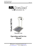
Model SR255 Daily-Weigh Scale Operating and Service Manual - S/N 3616+ Part No. MAN255_130628 S Model SR255 by SInstruments, Inc. Daily-Weigh Scale Operating and Service Manual Serial Numbers: 3616 + SInstruments, Inc., 600 Young Street, Tonawanda, NY 14150 Tel: 716-693-5977 Fax: 716-693-5854 URL: www.srscales.com email: [email protected] Copyright 2013 SInstruments, Inc. Page 1 of 23 Model SR255 Daily-Weigh Scale Operating and Service Manual - S/N 3616+ Part No. MAN255_130628 Page 2 of 23 TABLE OF CONTENTS TABLE OF FIGURES ......................................................................................................................3 PACKING CHECKLIST – SR255– ADULT .................................................................................4 PACKING CHECKLIST – SR255 – PEDIATRIC .......................................................................5 ASSEMBLY.......................................................................................................................................6 REPLACEMENT PARTS AND ACCESSORIES ........................................................................8 SYSTEM DESCRIPTION AND INTENDED USE .......................................................................9 MAINTENANCE AND CLEANING ..............................................................................................9 STORAGE AND TRANSPORTATION ......................................................................................10 SPECIFICATIONS.........................................................................................................................11 BUTTON FUNCTIONS .................................................................................................................12 BASIC SYSTEM OPERATION....................................................................................................12 BATTERY REPLACEMENT .......................................................................................................15 THEORY OF OPERATION .........................................................................................................16 CALIBRATION ..............................................................................................................................17 INITIALIZATION .........................................................................................................................18 TROUBLESHOOTING .................................................................................................................20 WARRANTY...................................................................................................................................21 NOTES .............................................................................................................................................22 SInstruments, Inc., 600 Young Street, Tonawanda, NY 14150 Tel: 716-693-5977 Fax: 716-693-5854 URL: www.srscales.com email: [email protected] Copyright 2013 SInstruments, Inc. Model SR255 Daily-Weigh Scale Operating and Service Manual - S/N 3616+ Part No. MAN255_130628 Page 3 of 23 TABLE OF FIGURES Figure 1: Assembled SR255 Daily-Weigh Scale ......................................................................... 6 Figure 2: Stretcher Cup Installed .................................................................................................. 6 Figure 3: Mast Placement and Screw............................................................................................ 7 Figure 4: Spreader Bar Connected in Receptacle ........................................................................ 7 Figure 5: T-Boom - Lifter Pump Connection ............................................................................... 7 Figure 6: Transducer Connected to T-Boom ............................................................................... 7 Figure 7: Transducer Cable Connection ...................................................................................... 7 Figure 8: Transducer - A-Frame Connected ................................................................................ 7 Figure 9: Velcro End of Stretcher Bar Channel on Stretcher ................................................. 8 Figure 10: A-Frame Hook Placement on Stretcher ..................................................................... 8 Figure 11: Stretcher Cup Receptacle for Transporting Scale .................................................. 10 Figure 12: Lifter Legs Opened/Closed ........................................................................................ 13 Figure 13: Lifter LOCK/ RELEASE Lever .................................................................................. 14 Figure 14: Battery Compartment Cover .................................................................................... 15 Figure 15: PC Board Access Cover ............................................................................................. 17 Figure 16: Location of Internal Calibration Buttons and Offset Potentiometer .................... 17 Figure 17: Location of Internal Initialization Buttons .............................................................. 18 SInstruments, Inc., 600 Young Street, Tonawanda, NY 14150 Tel: 716-693-5977 Fax: 716-693-5854 URL: www.srscales.com email: [email protected] Copyright 2013 SInstruments, Inc. Model SR255 Daily-Weigh Scale Operating and Service Manual - S/N 3616+ Part No. MAN255_130628 Page 4 of 23 PACKING CHECKLIST – SR255– ADULT DESCRIPTION Box 1 QUANTITY T-BOOM / MAST with INVACARE LIFTER 1 ea 1/4-20 x 1” SOCKET HEAD CAP SCREW (for Mast Assy.) 1 ea INVACARE LIFTER BASE 1 ea 3/8-16 x 1 ¼” SHOULDER BOLT (for T-Boom/Pump Assy.) 1 ea WASHER (for T-Boom/Pump Assy.) 1 ea 3/8-16 LOCK NUT (for T-Boom/Pump Assy.) 1 ea SPREADER BAR 1 ea TRANSDUCER TUBE 1 ea 6-32 x ½” SOCKET HEAD CAP SCREW (Safety ScrewTransducer Assy.) 2 ea STAPH-CHECK STRETCHER (32” x 72”) 1 ea STRETCHER CUP 1 ea DISPLAY / BATTERY BOX (pre-attached to mast) 1 ea SIX (6) “D” CELL BATTERIES 6 ea A-FRAME 2 ea 3/8-16 x 2 ¼” SHOULDER BOLT (for A-Frame Assy.) 2 ea 3/8-16 LOCK NUT (for A-Frame Assy.) 2 ea 3/16” ALLEN WRENCH 1 ea 7/64” ALLEN WRENCH 1 ea ½” OPEN END WRENCH 1 ea Box 2 STRETCHER BARS (72”) HARDWARE NOTE: All hardware is already in position and “finger tight”. No nuts, bolts or screws are packaged separately. SInstruments, Inc., 600 Young Street, Tonawanda, NY 14150 Tel: 716-693-5977 Fax: 716-693-5854 URL: www.srscales.com email: [email protected] Copyright 2013 SInstruments, Inc. 2 ea Model SR255 Daily-Weigh Scale Operating and Service Manual - S/N 3616+ Part No. MAN255_130628 Page 5 of 23 PACKING CHECKLIST – SR255 – PEDIATRIC DESCRIPTION Box 1 QUANTITY T-BOOM/MAST with INVACARE LIFTER 1 ea 1/4-20 x 1” SOCKET HEAD CAP SCREW (for Mast Assy.) 1 ea INVACARE LIFTER BASE 1 ea 3/8-16 x 1 ¼” SHOULDER BOLT (for T-Boom/Pump Assy.) 1 ea WASHER (for T-Boom/Pump Assy.) 1 ea 3/8-16 LOCK NUT (for T-Boom/Pump Assy.) 1 ea SPREADER BAR 1 ea TRANSDUCER TUBE 1 ea 6-32 x ½” SOCKET HEAD CAP SCREW (Safety ScrewTransducer Assy.) 2 ea STAPH-CHECK STRETCHER (32” x 60”) 1 ea STRETCHER CUP 1 ea DISPLAY / BATTERY BOX (pre-attached to mast) 1 ea SIX (6) “D” CELL BATTERIES 6 ea A-FRAME 2 ea 3/8-16 x 2 ¼” SHOULDER BOLT (for A-Frame Assy.) 2 ea 3/8-16 LOCK NUT (for A-Frame Assy.) 2 ea 3/16” ALLEN WRENCH 1 ea 7/64” ALLEN WRENCH 1 ea ½” OPEN END WRENCH 1 ea Box 2 STRETCHER BARS (60”) HARDWARE NOTE: All hardware is already in position and “finger tight”. No nuts, bolts or screws are packaged separately. SInstruments, Inc., 600 Young Street, Tonawanda, NY 14150 Tel: 716-693-5977 Fax: 716-693-5854 URL: www.srscales.com email: [email protected] Copyright 2013 SInstruments, Inc. 2 ea Model SR255 Daily-Weigh Scale Operating and Service Manual - S/N 3616+ Part No. MAN255_130628 Page 6 of 23 ASSEMBLY 7 6 4 8 5 10 4 9 3 11 13 12 2 14 15 15 1 Figure 1: Assembled SR255 Daily-Weigh Scale STEP 1: Unpack the scale system and check parts against the PACKING CHECKLIST. If there are any missing or damaged parts, please call the Service Hotline: 1-800-654-6360. STEP 2: (Figure 1) Verify that the serial number on the Display Unit (3) matches that on the Transducer Bar (6). STEP 3: (Figure 2) Attach the Stretcher Cup (15) to the Invacare Lifter Base (1), snapping it into place and twisting the lower tab back under the Mast (12), past the lower bolt. Figure 2: Stretcher Cup Installed # 1 2 3 4 5 6 7 8 9 10 11 12 13 14 15 PART NAME Invacare Lifter Base Spreader Bar Display Unit Stretcher Bracket T-Boom (Mast Hinge Connection) Transducer Bar (T-Boom Connection) Lifter Pump (T-Boom Connection) A-Frame (Stretcher Holders) A-Frame Hook (Stretcher Bar) Stretcher Stretcher Bar Channels Mast Mast Anchor Screw ¼-20x1 Socket Head Cap Screw Stretcher Cup Continued next page SInstruments, Inc., 600 Young Street, Tonawanda, NY 14150 Tel: 716-693-5977 Fax: 716-693-5854 URL: www.srscales.com email: [email protected] Copyright 2013 SInstruments, Inc. Model SR255 Daily-Weigh Scale Operating and Service Manual - S/N 3616+ Part No. MAN255_130628 Page 7 of 23 ASSEMBLY Cont’d STEP 4: (Figure 3) Loosen the 1/4-20 x 1 in Socket Head Cap Screw (14) found on the mast receptacle. Insert Mast (12) into Invacare Lifter Base (1) as shown. The bottom of the Mast is slotted. When properly set, the Mast will drop into place. The Display Unit (3) will face away from the lifter legs and be perpendicular to the Invacare Lifter Base. Tighten Socket Head Cap Screw to secure. Figure 3: Mast Placement and Screw STEP 5: (Figure 4) Insert the Spreader Bar (2) into the receptacle at the base of the Mast (12). Secure tightly with screw which is shipped “finger tight” in place on Invacare Lifter Base. Figure 4: Spreader Bar Connected in Receptacle STEP 6: (Figure 5) Attach and securely tighten the rod-end of the Lifter Pump (7) to the T-Boom (5) using 3/8-16 x 1 ¼ in shoulder bolt, washer and 3/8-16 lock nut. All are shipped “finger tight” in place on T-Boom. Also tighten the Mast/TBoom hinge lock nut securely. Figure 5: T-Boom - Lifter Pump Connection STEP 7: (Figure 6) Hang the Transducer Bar from the end of the T-Boom. Label on the Transducer Bar must face away from unit. Tighten safety screws as shown to prevent separation of TBoom and Transducer Bar. Figure 6: Transducer Connected to T-Boom STEP 8: (Figure 7) Plug in the transducer cable to the receptacle on the top end of the T- Boom. STEP 9: (Figure 8) Attach the two (2) A-Frames (8) to each end of the Transducer Bar using the two (2) 3/8-16 x 2 ¼ in shoulder bolts and two (2) 3/816 locknuts. Tighten securely. Figure 7: Transducer Cable Connection Figure 8: Transducer A-Frame Connected Continued next page SInstruments, Inc., 600 Young Street, Tonawanda, NY 14150 Tel: 716-693-5977 Fax: 716-693-5854 URL: www.srscales.com email: [email protected] Copyright 2013 SInstruments, Inc. Model SR255 Daily-Weigh Scale Operating and Service Manual - S/N 3616+ Part No. MAN255_130628 Page 8 of 23 ASSEMBLY Cont’d STEP 10: (Figure 9) Slide the stretcher bars into the sides of the Stretcher (10) by opening the Velcro tabs and inserting the stretcher bars. Re-seal the ends. (When not in use, store the Stretcher in the Stretcher Cup (15) at the base of the unit and tuck into the Stretcher Bracket (4) attached to the Display to hold it upright.) Figure 9: Velcro End of Stretcher Bar Channel on Stretcher STEP 11: (Figure 10) The Stretcher attaches to the AFigure 10: A-Frame Frames by inserting their hooked ends through the four Hook Placement on holes in the Stretcher. Stretcher REPLACEMENT PARTS and ACCESSORIES Part # SR290 SR295-SCR SR290P SR295-PSC PF0755I SM1932 FRSPREADER FC6382-4SG FC7381-4PG CA3066 FCMS3116F8 MAN255 SR285 SR285-Q Description 72” Stretcher Bars (Adult) 72” Stretcher (Adult) 60” Stretcher Bars (Pediatric) 60” Stretcher (Pediatric) Stretcher Cup T-Boom Spreader Bar Handle 4-Pin Connector (T-Boom) 4-Pin Connector (Display) Display Label Transducer Connector Service Manual. Please provide S/N when ordering. Disposable Stretcher Covers (Box of 200) Disposable Stretcher Covers (Box of 50) SInstruments, Inc., 600 Young Street, Tonawanda, NY 14150 Tel: 716-693-5977 Fax: 716-693-5854 URL: www.srscales.com email: [email protected] Copyright 2013 SInstruments, Inc. Model SR255 Daily-Weigh Scale Operating and Service Manual - S/N 3616+ Part No. MAN255_130628 Page 9 of 23 SYSTEM DESCRIPTION and INTENDED USE SYSTEM DESCRIPTION The SR255 Daily-Weigh Scale employs the latest in microprocessor and load cell technology to provide accurate and repeatable weight data. Two (2) identically matched transducers are strategically placed to ensure an accurate representation of the patient’s weight. The low power microprocessor circuitry allows the SR255 to derive its power from six (6) common “D” cell batteries that will provide up to 10,000 weight readings before needing replacement. This eliminates the need for an external battery charger or the danger of an AC power supply cord on a portable scale. The patient’s weight is displayed on a 16-character dot-matrix LCD. With a push of a button, weight data may be viewed, in either pounds or kilograms, with a displayed resolution of 0.1 lb. or 0.1 kg. INTENDED USE The SR255 Daily-Weigh Scale is designed for use as a patient weighing system for non-ambulatory patients only. Please read the following warnings to avoid injury to the patient or attendant. The SR255 DailyWeigh Scale is a preferred means of gathering patient weight data of nonambulatory patients weighing up to 400 pounds. The transducer bar, using load cell technology, ensures accurate and repeatable weight readings. WARNING DO NOT USE FOR PATIENT TRANSPORT. MAXIMUM 400 LB / 181 KG CAPACITY. SPREAD THE LEGS OF THE LIFTER BASE PRIOR TO LIFTING AND WEIGHING PATIENT. DO NOT USE THE PUMP HANDLE TO MANEUVER THE SCALE Failure to spread the legs prior to suspending patient could cause lifter to tip over and injure patient and/or attendant. MAINTENANCE and CLEANING Exercise caution when cleaning the display window as it is made of clear polyester and can be scratched by abrasive cleaners. Mild soap and water is recommended for general cleaning and disinfecting. The Hydraulic Pump is a factory sealed unit and MUST be returned for service. WARNING DO NOT use pressurized water or steam. The scale system contains microprocessor circuitry and strain gauge sensors that may be adversely affected by exposure to such an environment. SInstruments, Inc., 600 Young Street, Tonawanda, NY 14150 Tel: 716-693-5977 Fax: 716-693-5854 URL: www.srscales.com email: [email protected] Copyright 2013 SInstruments, Inc. Model SR255 Daily-Weigh Scale Operating and Service Manual - S/N 3616+ Part No. MAN255_130628 Page 10 of 23 STORAGE and TRANSPORTATION STORAGE If storing this equipment for periods longer than three (3) months, remove the batteries. To maintain proper operation of this instrumentation, storage and transport conditions should not vary outside the following conditions: Relative humidity 0% to 85%, Ambient Temperature 14F to 122F (-10 C to +50C). TRANSPORTATION To transport the SR255 Daily-Weigh Scale from one location to another within the building, remove the Stretcher from the Stretcher Bar Hooks, roll up and place in the Stretcher Cup located at the base of the scale and behind the Stretcher Bracket located behind the Display Box. Figure 11: Stretcher Cup Receptacle for Transporting Scale SInstruments, Inc., 600 Young Street, Tonawanda, NY 14150 Tel: 716-693-5977 Fax: 716-693-5854 URL: www.srscales.com email: [email protected] Copyright 2013 SInstruments, Inc. Model SR255 Daily-Weigh Scale Operating and Service Manual - S/N 3616+ Part No. MAN255_130628 Page 11 of 23 SPECIFICATIONS MAXIMUM WEIGHT CAPACITY STRETCHER SIZE DISPLAY TYPE DISPLAY RESOLUTION 400 lb or 181 kg Adult: 32 in x 72 in Pediatric: 32 in x 60 in 16-Character dot-matrix LCD 0.1 lb or 0.1 kg ACCURACY 0.1% +/- 1 digit of displayed resolution for calibrated range AUTO ZERO One button operation AUTO POWER DOWN HOLD LAST WEIGHT RECALL AVERAGING POWER SUPPLY CALIBRATION After 35 seconds While active, freezes display data and stores it in memory “Hold” button recalls last stored weight Automatic digital filter Six (6) “D” cell batteries Calibration is traceable to NIST standards OPERATING CONDITIONS Normal operating conditions for this product: Temperature Range: 68F to 85F (20C to 30C), Relative Humidity Range: 0%-85%. Avoid exposure to high-pressure water or steam. TRANSPORT and STORAGE Storage and transport conditions should not vary outside the following conditions: Relative Humidity 0% to 85%, Ambient Temperature 14F to 122F (-10 C to +50C). Remove batteries if storing longer than three (3) months. SInstruments, Inc., 600 Young Street, Tonawanda, NY 14150 Tel: 716-693-5977 Fax: 716-693-5854 URL: www.srscales.com email: [email protected] Copyright 2013 SInstruments, Inc. Model SR255 Daily-Weigh Scale Operating and Service Manual - S/N 3616+ Part No. MAN255_130628 Page 12 of 23 BUTTON FUNCTIONS Press box under each icon to activate command ZERO The “ZERO” button is used to zero the system before placing a patient onto the scale system. When pressed, the display message will indicate “PLEASE WAIT” “WEIGHING” “HANDS OFF”. Ensure that nothing is in contact with the weighing surface during this procedure. The display will read “WEIGHT 0.0 LB” (or KG). WEIGH The “WEIGH” button wakes up the display and shows the patient’s weight if it should Auto Power Down before the weighing process is done. HOLD The “HOLD” button freezes the displayed weight and temporarily stores it away in memory. Press “HOLD” to store the weight into memory. To recall last weight reading, press “HOLD”. LB/KG MODE Weight data may be viewed in either pounds or kilograms. Pressing the “LB/KG MODE” button allows the operator to toggle between the two readings. Both pounds and kilograms are displayed in a resolution of 0.1. BASIC SYSTEM OPERATION ZERO With the stretcher in place (without the patient), make sure scale is free and clear of any obstructions and press the “ZERO” button. The displayed message will indicate “PLEASE WAIT” “WEIGHING” “HANDS OFF”. Make sure that nothing is in contact with the scale while zeroing the system. In a few seconds the display will read “WEIGHT = 0.0 LB (or KG)”. Note: If a pillow or blanket is to be added for patient comfort, place them on the scale before performing the ZERO function so they will not be included in the patients’ weight. Continued next page SInstruments, Inc., 600 Young Street, Tonawanda, NY 14150 Tel: 716-693-5977 Fax: 716-693-5854 URL: www.srscales.com email: [email protected] Copyright 2013 SInstruments, Inc. Model SR255 Daily-Weigh Scale Operating and Service Manual - S/N 3616+ Part No. MAN255_130628 Page 13 of 23 BASIC SYSTEM OPERATION Cont’d CONTINUOUS WEIGH In this default mode, the weighing surface remains active. Press the “HOLD” button once to lock the displayed reading and store it in memory as the “last weight” for recall later if needed. AUTO-HOLD This mode is for patients unable to remain still for the weighing procedure. It locks, stores, and displays the patient’s weight as soon as the “WEIGH” button is pressed once. Note: No weight will be displayed until the button is pressed. To enable this mode, BEFORE zeroing the system, press and hold the “HOLD” button for approximately five (5) seconds until the display reads “AUTO-HOLD ENABLED”. To return to CONTINUOUS WEIGH mode when finished, press and hold the “HOLD” button for approximately five (5) seconds until the display reads “CONTINUOUS WEIGH”. STEP 1: Remove the Stretcher and position it under the patient. Include any additional items used when zeroing the system. Note: The bulk of the patient’s mass must be centered on the Stretcher for proper balance. STEP 2: (Figure 12) SPREAD LEGS ON PATIENTLIFTER BEFORE ATTEMPTING TO LIFT THE PATIENT! CLOSED OPEN Figure 12: Lifter Legs Opened/Closed Continued next page SInstruments, Inc., 600 Young Street, Tonawanda, NY 14150 Tel: 716-693-5977 Fax: 716-693-5854 URL: www.srscales.com email: [email protected] Copyright 2013 SInstruments, Inc. Model SR255 Daily-Weigh Scale Operating and Service Manual - S/N 3616+ Part No. MAN255_130628 Page 14 of 23 BASIC SYSTEM OPERATION Cont’d STEP 3: (Figure 13) To RAISE the T-Boom, the Lock/ Release Lever on the lifter must be in the LOCK position (left). Pump the handle. To LOWER the T-Boom, the Lock/Release lever on the lifter must be in the RELEASE position (right). Patient’s weight will slowly lower the T-Boom. STEP 4: With the T-Boom raised, roll the scale forward so the two (2) A-Frames are centered over the patient. DO NOT USE THE PUMP HANDLE TO MANEUVER THE SCALE! Lower the TBoom and attach the A-Frame hooks into the Stretcher holes. Move the lever into the LOCK position. DO NOT EXCEED THE MAXIMUM CAPACITY OF 400 LB/ 181 KG. STEP 5: When the Stretcher is securely attached, pump handle until the patient is raised just enough to clear the bed and any linens, etc. Weigh patient and when finished, lower back on to the bed by moving the Lock/Release Lever to RELEASE (right). Patient’s weight will lower the Stretcher slowly. Unhook the Stretcher and again raise the TBoom so the patient can be safely moved. DO NOT ATTEMPT TO TRANSPORT PATIENT VIA THE SCALE! Figure 13: Lifter LOCK/ RELEASE Lever STEP 6: It is recommended that you re-zero before each weighing to ensure optimal accuracy. NOTE: Do not touch patient, stretcher or circular A-Frames during the weighing process. By design, these components are weight sensitive and any interference will affect the accuracy of the weight data. WARNING DO NOT USE FOR PATIENT TRANSPORT. MAXIMUM 400 LB / 181 KG CAPACITY SPREAD THE LEGS OF THE LIFTER BASE PRIOR TO LIFTING AND WEIGHING PATIENT Failure to spread the legs prior to suspending patient could bend legs or cause lifter to tip over and injure patient and/or attendant. DO NOT USE THE PUMP HANDLE TO MANEUVER THE SCALE SInstruments, Inc., 600 Young Street, Tonawanda, NY 14150 Tel: 716-693-5977 Fax: 716-693-5854 URL: www.srscales.com email: [email protected] Copyright 2013 SInstruments, Inc. Model SR255 Daily-Weigh Scale Operating and Service Manual - S/N 3616+ Part No. MAN255_130628 Page 15 of 23 BATTERY REPLACEMENT STEP 1: The display will read “CHANGE BATTERY” when the batteries are low. STEP 2: Unscrew the four (4) screws and open the Battery Compartment Cover on the front of the Display Unit. STEP 3: Remove and replace ALL six (6) “D” cell batteries. Refer to diagram in the battery compartment for placement. STEP 4: Press the “WEIGH” button to confirm display is working. STEP 5: Replace the Battery Compartment Cover and replace the four (4) screws. STEP 6: Zero the system. Figure 14: Battery Compartment Cover SInstruments, Inc., 600 Young Street, Tonawanda, NY 14150 Tel: 716-693-5977 Fax: 716-693-5854 URL: www.srscales.com email: [email protected] Copyright 2013 SInstruments, Inc. Model SR255 Daily-Weigh Scale Operating and Service Manual - S/N 3616+ Part No. MAN255_130628 Page 16 of 23 THEORY OF OPERATION SR Instruments patient weighing systems are digital scales. Strain-gauge force cells convert the force of an applied weight into an analog signal. This signal is amplified by an operational amplifier and converted to a digital signal by an analog to digital converter. The digital signal is transferred to a micro-controller where it is filtered, converted to appropriate units and displayed on a liquid crystal display. Strain-gauge force cells each contain four strain gauges mounted in a full Wheatstone-bridge configuration. These bridges convert the physical movement of the force cell, due to the applied mass on the system, into minute changes in electrical resistance. These changes in resistance produce a voltage difference across the Wheatstone-bridge, which is amplified by the operational amplifier. The amplifier is configured to current sum the output of each cell, with potentiometers serving to adjust the sensitivity (voltage out per unit of weight applied) of each bridge. The offset potentiometer produces a small current, which nulls the output of the amplifier for an unloaded system. The output of the operational amplifier is digitized by the analog to digital converter. The converter integrates the analog signal onto the integrating capacitor over a short interval. The integrating capacitor is then discharged at a rate proportional to the reference voltage applied to the converter. The residual voltage on the integrating capacitor is then multiplied by a factor and again discharged at a rate proportional to the reference voltage. The residual voltage from this discharge is again multiplied by a factor and again discharged. The time taken to discharge the capacitor is proportional to the voltage from the operational amplifier, which is proportional to the applied load on the force cells. The time is stored as a binary number in the analog to digital converter and is transferred to the micro-controller when the conversion is complete. The micro-controller averages and filters the digital output of the analog to digital converter, subtracts the value saved during the system zero operation and scales the filtered output, then displays the result on the liquid crystal display. The micro-controller performs a rolling average of data for continuous weigh and, for AutoHold, the micro-controller averages the data before locking in on the reading. If the data variance is greater than 0.1% in the AutoHold mode, the micro-controller will reset the filter and start a new averaging period. The micro-controller can be placed in a calibration mode, where the system can be re-calibrated. In the calibration mode, the result of the weigh operation is scaled to match the value by adjusting the “up” and “down” calibration buttons. This new calibration factor is then stored in the non-volatile memory. SInstruments, Inc., 600 Young Street, Tonawanda, NY 14150 Tel: 716-693-5977 Fax: 716-693-5854 URL: www.srscales.com email: [email protected] Copyright 2013 SInstruments, Inc. Model SR255 Daily-Weigh Scale Operating and Service Manual - S/N 3616+ Part No. MAN255_130628 Page 17 of 23 CALIBRATION IMPORTANT CALIBRATION CHECK Qualified service personnel only should perform this procedure. Load cells have no user serviceable components and should not be tampered with for any reason. Re-calibration is generally not required, but should be verified periodically to ensure accuracy. The recommendation for calibration check is at least once every 12 months, or as individual maintenance policy requires. NOTE: Ensure that nothing is in contact with the scale system during this procedure. Remove hands from the system when noting the displayed calibration results. STEP 1: housing. (Figure 15) Remove the four (4) screws on the back of the display Figure 15: PC Board Access Cover “-” “+” “-“ “+” Figure 16: Location of Internal Calibration Buttons and Offset Potentiometer STEP 2: (Figure 16) The Calibration buttons are located internally on the PC Board as indicated. Press the internal calibration buttons (SW5 and SW6) simultaneously to put system into calibration mode. STEP 3: The display will read, “HOLD TO CAL” as the digit in the right hand corner counts down from 9 to 0. The display will then read “CALIBRATION” and periodically flash this on the display. In the far left corner of the display the letters “CAL” will appear. CALIBRATION TOLERANCE TABLE LOW LIMIT APPLIED LOAD HIGH LIMIT 99.9 100.0 100.1 199.8 200.0 200.2 299.7 300.0 300.3 399.6 400.0 400.4 Continued next page SInstruments, Inc., 600 Young Street, Tonawanda, NY 14150 Tel: 716-693-5977 Fax: 716-693-5854 URL: www.srscales.com email: [email protected] Copyright 2013 SInstruments, Inc. Model SR255 Daily-Weigh Scale Operating and Service Manual - S/N 3616+ Part No. MAN255_130628 Page 18 of 23 CALIBRATION Cont’d CAUTION The integrated circuits and semiconductors on the printed circuit boards may be damaged by electrostatic discharge (ESD). Be sure to use proper handling precautions at all times. STEP 4: System offset is displayed on the right side of the screen and should read between +35 and +40 pounds. Use a fine blade screwdriver to adjust Offset Potentiometer (R13). STEP 5: When in CAL mode, press the “ZERO” button to zero the display. STEP 6: Center a known calibrated weight, traceable to NIST, on the stretcher and compare to display reading. STEP 7: Adjust the reading, using the “+” or “-” buttons to match the weight. Display should be within 0.1% of the calibrated weight. See Calibration Tolerance Table. STEP 8: Remove the weight and re-zero. Repeat steps 5, 6, and 7 until correct. STEP 9: When settings are completed: Press the “HOLD” button to SAVE the settings or press the “WEIGH” button to CANCEL. Both choices will EXIT the CAL mode. INITIALIZATION INITIALIZATION PROCEDURE To be used ONLY IF REPLACING IC5 or if DISPLAY READS DOUBLE Internal Initialization Buttons SW5 SW2 Figure 17: Location of Internal Initialization Buttons Continued next page SInstruments, Inc., 600 Young Street, Tonawanda, NY 14150 Tel: 716-693-5977 Fax: 716-693-5854 URL: www.srscales.com email: [email protected] Copyright 2013 SInstruments, Inc. Model SR255 Daily-Weigh Scale Operating and Service Manual - S/N 3616+ Part No. MAN255_130628 Page 19 of 23 INITIALIZATION Cont’d STEP 1: Remove the four (4) screws on the back of the display housing. (Figure 17) The Initialization Buttons (SW2 and SW5) are located internally on the PC Board as indicated. STEP 2: Simultaneously press buttons indicated to initialize the system. The display will read, “HOLD TO INIT” and count down from 9 to 0. When the initializing is complete, the display will read, “INITIALIZING” and then return to the WEIGH mode. STEP 3: Follow the CALIBRATION procedure. CAUTION The integrated circuits and semiconductors on the printed circuit boards may be damaged by electrostatic discharge (ESD). Be sure to use proper handling precautions at all times. SInstruments, Inc., 600 Young Street, Tonawanda, NY 14150 Tel: 716-693-5977 Fax: 716-693-5854 URL: www.srscales.com email: [email protected] Copyright 2013 SInstruments, Inc. Model SR255 Daily-Weigh Scale Operating and Service Manual - S/N 3616+ Part No. MAN255_130628 Page 20 of 23 TROUBLESHOOTING SYMPTOM REASON/CORRECTIVE ACTION The characters only appear on half of the display. Press the “WEIGH” button or remove one battery. Wait five seconds, then re-install the battery and try the “WEIGH” button again. The display lights appear to work but does not respond to button activation. Button may not have “bounced” back up after being pressed. Remove the label facing and inspect buttons. Make sure the rubber “boot” is not sitting too high. Re-attach label. The display shows no reading at all. Check to ensure batteries are installed correctly (see directions for BATTERY REPLACEMENT). Check transducer and readout cables to make sure they are connected securely. The display reads “WEIGHT OVERLOAD”. Check to ensure the transducer wire is intact. A broken transducer wire or a bad T-Boom cable can cause this reading. The display shows a double weight reading. This happens when the IC5 fails. For repair information see INITIALIZATION PROCEDURE. The pump could stay in the upright position until a downward force is applied. This is acceptable behavior and is not considered a warranty issue. It could take up to 30 lbs. of downward force to lower the boom arm. If, when boom is moved downward, there are “sticking” points where the force to lower is much greater and downward motion is erratic and not smooth. This type of scenario implies that there could be air bubbles trapped in the system that could have been created by (a) Closing the Lock/Release Lever Arm and forcing the pump handle upward without using the pump handle and/or (b) during the shipping process. Possible Remedy: Please try the following: (1) Close the Lock/Release Lever Arm and use the pump handle to raise the boom until it stops, (2) open the Lock/Release Lever Arm and slowly lower the boom arm with the required force until the boom stops, (3) repeat steps (1) and (2) two more times. A small amount of hydraulic oil (about) a drop will accumulate around the piston from time to time and is normal. This is not a warranty issue and the oil may be removed with a facial tissue. For additional information or assistance, telephone our Service Hotline: 1-800-654-6360 or e-mail: [email protected] SInstruments, Inc., 600 Young Street, Tonawanda, NY 14150 Tel: 716-693-5977 Fax: 716-693-5854 URL: www.srscales.com email: [email protected] Copyright 2013 SInstruments, Inc. Model SR255 Daily-Weigh Scale Operating and Service Manual - S/N 3616+ Part No. MAN255_130628 Page 21 of 23 WARRANTY 2 YEAR LIMITED WARRANTY Each S system is manufactured with high quality components. SR Instruments, Inc. warrants that all new equipment will be free from defects in material or workmanship, under normal use and service, for a period of two (2) years from the date of purchase by the original purchaser. Normal wear and tear, injury by natural forces, user neglect, and purposeful destruction are not covered by this warranty. Warranty service must be performed by the factory or an authorized repair station. Service provided on equipment returned to the factory or authorized repair station includes labor to replace defective parts. Goods returned must be shipped with transportation and/or broker charges prepaid. SR Instruments, Inc.’s obligation is limited to replacement of parts that have been so returned and are disclosed to SR Instruments, Inc.’s satisfaction to be defective. The provisions of this warranty clause are in lieu of all other warranties, expressed or implied, and of all other obligations or liabilities on SR Instruments, Inc.’s part, and it neither assumes nor authorizes any other person to assume for SR Instruments, Inc. any other liabilities in connection with the sale of said articles. In no event shall SR Instruments, Inc. be liable for any subsequent or special damages. Any misuse, improper installation, or tampering, shall void this warranty. DAMAGED SHIPMENTS Title passes to purchaser upon delivery to Transportation Company. Any claims for shortage or damage should be filed with the delivery carrier by purchaser. RETURN POLICY All products being returned to SR Instruments, Inc. require a Return Goods Authorization number (RGA). To receive an RGA, call our Technical Service Team at 716-693-5977 or toll-free in the USA and Canada at 800-654-6360. When inquiry is made, please supply model and serial numbers, purchase order, if the scale was bought on contract, and reason for return. Generally, deleted, damaged, and outdated merchandise will not be accepted for credit. minimum restocking charge of 15% will be assessed on return of current merchandise. A All returns are to be shipped FREIGHT PREPAID to: SR Instruments, Inc., 600 Young Street, Tonawanda, NY 14150. RESTOCKING FEE 15% fee for any scale that has been opened and used 10% fee for any scale returned that has been ordered incorrectly or refused delivery with no model change 5% fee if an error in ordering has been made and a different model exchanged No fees will be charged if the scale is returned because of an error on the part of SR Instruments, Inc. No returns accepted after 60 days. SInstruments, Inc., 600 Young Street, Tonawanda, NY 14150 Tel: 716-693-5977 Fax: 716-693-5854 URL: www.srscales.com email: [email protected] Copyright 2013 SInstruments, Inc. Model SR255 Daily-Weigh Scale Operating and Service Manual - S/N 3616+ Part No. MAN255_130628 Page 22 of 23 NOTES SInstruments, Inc., 600 Young Street, Tonawanda, NY 14150 Tel: 716-693-5977 Fax: 716-693-5854 URL: www.srscales.com email: [email protected] Copyright 2013 SInstruments, Inc. Model SR255 Daily-Weigh Scale Operating and Service Manual - S/N 3616+ Part No. MAN255_130628 S By SInstruments, Inc. Precision & Technology in Perfect Balance ® SInstruments, Inc., 600 Young Street, Tonawanda, NY 14150 Tel: 716-693-5977 Fax: 716-693-5854 URL: www.srscales.com email: [email protected] Copyright 2013 SInstruments, Inc. Page 23 of 23