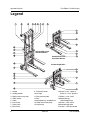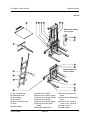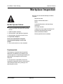
1
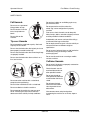
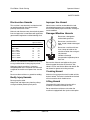
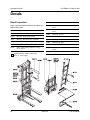
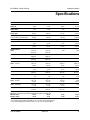
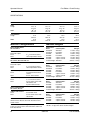
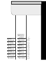
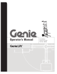
Operator’s Manual
First Edition
Fourth Printing
Part No. 35566
Operator's Manual
First Edition • Fourth Printing
Important
Read, understand and obey these safety rules and
operating instructions before operating this machine.
Only trained and authorized personnel shall be
permitted to operate this machine. If you have any
questions, call Genie Industries.
Contents
Page
Operator's Manual
Safety ......................................................................... 1
Legend ....................................................................... 6
Pre-operation Inspection ............................................. 8
Function Tests .......................................................... 10
Workplace Inspection ............................................... 13
Operating Instructions .............................................. 14
Battery & Charger Operating Instructions ................. 16
Transport Instructions ............................................... 17
Load Capacity Charts ............................................... 18
Decals ...................................................................... 20
Specifications ........................................................... 21
Copyright © 1995 by Genie Industries
Contact us:
First Edition:
Internet: http://www.genielift.com
e-mail: [email protected]
Fourth Printing, September 2001
"Genie" is a registered trademark of
Genie Industries in the USA and many other
countries.
Printed on recycled paper
Printed in U.S.A.
Genie Lift
Part No. 35566
First Edition • Fourth Printing
Operator's Manual
Safety Rules
Warning
Failure to obey the instructions and
safety rules in this manual may
result in death or serious injury.
Do Not Operate Unless:
You learn and practice the principles of safe
machine operation contained in this operator's
manual.
1 Avoid hazardous situations.
Know and understand the safety rules
before going on to the next section.
2 Always perform a pre-operation
inspection.
3 Always perform the function tests prior to
use.
4 Inspect the workplace.
5 Only use the machine as it was intended.
You read, understand and obey:
manufacturer's instructions and safety
rules—operator's manual and machine
decals
employer's safety rules and worksite
regulations
applicable governmental regulations
Part No. 35566
Genie Lift
1
Operator's Manual
First Edition • Fourth Printing
SAFETY RULES
Do not place ladders or scaffolding against any
part of the machine.
Fall Hazards
Do not use as a personnel
lifting platform or step.
Do not operate the machine unless the
wheel / leg / caster configuration is properly
installed.
Do not stand or sit on the
forks, load platform or
boom.
Prior to use, check the work area for drop-offs,
holes, bumps, debris, unstable or slippery surfaces
or other possible hazardous conditions.
Do not climb on the
machine.
Avoid debris and uneven surfaces while rolling a
machine with the legs not installed.
Tip-over Hazards
Do not exceed the rated load capacity. See Load
Capacity Charts section.
Do not raise the load unless the leg lock pins have
been properly inserted into the legs.
Do not raise the load unless the correct length legs
are properly installed.
Do not raise the load unless the machine is on a
firm, level surface.
Do not replace machine parts critical to stability or
structure with items of different weight or
specification.
Do not cause a horizontal force or side load to the
machine by raising or lowering a fixed or
overhanging load.
Do not use the machine on a moving or mobile
surface or vehicle.
Collision Hazards
Do not raise if the load is not properly centered on
the forks or load platform.
Check the work area for
overhead obstructions or
other possible hazards.
Do not move the machine with a raised load,
except for minor positioning.
Do not tilt the machine back with a raised load.
Do not use blocks to level the machine.
Do not operate the machine in strong or gusty
winds. Increasing the load surface area will
decrease machine stability in windy conditions.
2
Do not stand under or
allow personnel under the
machine when the load is
raised.
Do not lower the load
unless the area below is
clear of personnel and
obstructions.
Use common sense and planning when
transporting the machine on an incline, slope or
stairs.
Genie Lift
Part No. 35566
First Edition • Fourth Printing
Operator's Manual
SAFETY RULES
Electrocution Hazards
Improper Use Hazard
This machine is not electrically insulated and will
not provide protection from contact with or
proximity to electrical current.
Never leave a machine unattended with a load.
Unauthorized personnel may attempt to operate
the machine without proper instruction, creating an
unsafe condition.
Maintain safe distances away from electrical power
lines and apparatus in accordance with applicable
governmental regulations and the following chart.
Damaged Machine Hazards
Do not use a damaged or
malfunctioning machine.
Voltage
Minimum Safe
Approach Distance
Phase to Phase
Feet
0 to 300V
300V to 50KV
50KV to 200KV
200KV to 350KV
350KV to 500KV
500KV to 750KV
750KV to 1000KV
Avoid Contact
10
3.1
15
4.6
20
6.1
25
7.6
35
10.7
45
13.7
Do not use a machine with a
worn, frayed, kinked or damaged
cable.
Meters
Do not use a machine with less
than 4 wraps of cable on the
winch drum when the carriage is
fully lowered.
Conduct a thorough
pre-operation inspection prior to
each use.
Allow for mast movement and electrical line sway
or sag, and be aware of strong or gusty winds.
Keep away from the machine if it contacts
energized power lines. Personnel must not touch
or operate the machine until power lines are shut
off.
Do not use the machine as a ground for welding.
Bodily Injury Hazards
Do not grasp the cable.
Keep hands and fingers away from the pulleys,
carriage and other potential pinch points.
Be sure that all decals are legible and in place.
Maintain proper lubrication on the winch. See
Genie Lift Parts and Service Manual for details. Do
not allow oil or grease on braking surfaces.
Crushing Hazard
Maintain a firm grasp on the winch handle until the
brake is locked. The brake is locked when the load
will not cause the winch handle to turn.
Lifting Hazard
Use proper lifting techniques to load or tip the
machine, or move the machine on stairs.
Do not move the machine on stairs when the
machine is equipped with the 4 point caster option.
Part No. 35566
Genie Lift
3
Operator's Manual
First Edition • Fourth Printing
SAFETY RULES
Ladder Safety
Electric Winch Safety
Fall Hazards
Electrocution Hazard
Do not use the ladder as scaffolding.
Do not operate the DC battery charger unless
using a 3-wire grounded extension cord connected
to a grounded AC circit. Do not alter or disable
3-wire grounded plugs.
Do not sit on the ladder.
Do not over reach. Keep your body centered
between both side rails.
Tip-over Hazards
Do not use the top rung as a step.
Do not exceed the rated load capacity. See Load
Capacity Charts section.
Tip-over Hazards
Do not exceed the ladder's maximum capacity of
250 lbs / 113 kg.
Do not use the electric winch on models with the
standard base. The electric winch is designed for
use only on straddle base models.
Do not overload the ladder. Ladders are designed
for 1 person only.
Do not alter or disable the limit switch.
Do not use the ladder unless it is properly set up.
Battery and Charger Safety
- Electric Winch Models
Do not shift the ladder while on it. Avoid pushing or
pulling off to the side of the ladder.
Burn Hazards
Do not set up the ladder on slippery surfaces.
Batteries contain acid.
Always wear protective
clothing and eyewear
when working with
batteries.
Do not use blocks to level the ladder.
Avoid spilling or
contacting battery acid.
Neutralize battery acid
spills with baking soda
and water.
The battery pack must
remain in an upright position.
4
Genie Lift
Part No. 35566
First Edition • Fourth Printing
Operator's Manual
SAFETY RULES
Explosion Hazards
Decal Legend
Batteries emit explosive
gas. Keep sparks, flames
and lighted tobacco away
from the battery.
Genie product decals use symbols, color coding
and signal words to identify the following:
Safety alert symbol—used to alert
personnel to potential personal
injury hazards. Obey all safety
messages that follow this symbol
to avoid possible injury or death.
Charge the battery in a
well-ventilated area.
Do not disconnect the charger DC output wires
from the battery when the charger is on.
Red—used to indicate the
presence of an imminently
hazardous situation which, if not
avoided, will result in death or
serious injury.
Electrocution Hazards
Connect the charger to a
grounded AC circuit only.
Do not expose the battery
or charger to water or rain.
Before each use, inspect
for damage. Replace
damaged components
before operating.
Orange—used to indicate the
presence of a potentially
hazardous situation which, if not
avoided, could result in death or
serious injury.
Yellow with safety alert symbol—
used to indicate the presence of a
potentially hazardous situation
which, if not avoided, may cause
minor or moderate injury.
Lifting Hazard
The battery pack weighs 80 lbs / 37 kg. Use the
appropriate number of people and proper lifting
techniques when lifting the battery pack.
Yellow without safety alert
symbol—used to indicate the
presence of a potentially
hazardous situation which, if not
avoided, may result in property
damage.
Green—used to indicate operation
or maintenance information.
Part No. 35566
Genie Lift
5
Operator's Manual
First Edition • Fourth Printing
Legend
Standard Base with
Standard Wheels
Straddle Base with
Pneumatic Wheels
Counterweight Base
1
2
3
4
5
6
7
8
6
Handle
Loading wheels
Upper inner frame pulley
Cable anchor
Cable
Inner frame
Outer frame
Decal Plate
9 Pneumatic wheel
10 Carriage
11 Fork mounting tube
12 Fork
13 Adjustable leg - straddle base
14 Lower inner frame pulley
15 Leg lock pin
Genie Lift
16 Caster, 2 inch - option A
Caster, 21/2 inch - option B
17 Wheel - 4 inch fixed
18 Adjustable leg counterweight base
19 Caster - 5 inch swivel
20 Counterweight base
21 Caster - 2 inch dual wheel
Part No. 35566
First Edition • Fourth Printing
Operator's Manual
LEGEND
Models with electric
winch option
Straddle Base with
4 Point Casters
22 Leg - standard base
23 Solid rubber wheel
24 Brake (option)
25 Fork lock pin
26 Winch mounting bracket
27 Winch
28 Boom (option)
Part No. 35566
29 Load Platform (option)
30 Electric winch battery (option)
31 Electric winch charger (option)
32 Electric winch (option)
33 Electric winch control (option)
34 Electric winch limit switch
(option)
35 Emergency Stop switch
Genie Lift
36 Electric winch control up
button
37 Electric winch control down
button
38 Caster, 4 inch - option A
Caster, 5 inch - option B
39 Ladder snap pin
40 Ladder (option)
7
Operator's Manual
First Edition • Fourth Printing
Pre-operation Inspection
Fundamentals
The Pre-operation Inspection is a visual inspection
performed by the operator prior to each work shift.
This inspection is designed to discover if anything
is apparently wrong with a machine before the
operator tests it.
Do Not Operate Unless:
You learn and practice the principles of safe
machine operation contained in this operator's
manual.
1 Avoid hazardous situations.
2 Always perform a pre-operation inspection.
Know and understand the pre-operation
inspection before going on to the next
section.
3 Always perform function tests prior to use.
4 Inspect the workplace.
5 Only use the machine as it was intended.
8
Inspect the machine for modifications, damage or
loose or missing parts.
A damaged or modified machine must never be
used. If damage or any variation from factory
delivered condition is discovered, the machine
must be tagged and removed from service.
Repairs to the machine may only be made by a
qualified service technician, according to the
manufacturer's specifications. After repairs are
completed, the operator must perform a preoperation inspection again before testing the
machine functions.
Genie Lift
Part No. 35566
First Edition • Fourth Printing
Operator's Manual
PRE-OPERATION INSPECTION
Pre-operation Inspection
o Be sure that the operator’s manual is complete,
legible and available for reference.
Check the entire machine for:
o Dents or damage
o Be sure that all decals are legible and in place.
See Decals section.
Check the following components or areas for
damage, modifications and improperly installed or
missing parts:
o Winch and related components
o Base components
o Legs
o Roller wheels
o Inner and outer frames
o Corrosion or oxidation
o Cracks in welds or structural components
o Be sure that all structural and other critical
components are present and all associated
fasteners and pins are in place and properly
tightened.
o Inspect and clean the battery terminals and all
battery cable connections.
o Be sure there is a minimum of 4 wraps of cable
around the winch drum when the carriage is
fully lowered.
o Glide buttons
o Carriage hold-down assembly
o Cable anchor
o Cable and pulleys
o Wheels and casters
o Forks
o Load platform and boom (if equipped)
o Nuts, bolts and other fasteners
o Cable (kinks, frays, abrasions)
o Ladder (if equipped)
o Brake system (if equipped)
o Limit switch (if equipped)
o Electric winch and related components
(if equipped)
o Hand controls and wiring (if equipped)
Part No. 35566
Genie Lift
9
Operator's Manual
First Edition • Fourth Printing
Function Tests
Fundamentals
The Function Tests are designed to discover any
malfunctions before the machine is put into service.
The operator must follow the step-by-step
instructions to test all machine functions.
Do Not Operate Unless:
You learn and practice the principles of safe
machine operation contained in this operator's
manual.
1 Avoid hazardous situations.
2 Always perform a pre-operation inspection.
3 Always perform function tests prior to use.
A malfunctioning machine must never be used. If
malfunctions are discovered, the machine must be
tagged and removed from service. Repairs to the
machine may only be made by a qualified service
technician, according to the manufacturer's
specifications.
After repairs are completed, the operator must
perform a pre-operation inspection and function
tests again before putting the machine into service.
Know and understand the function tests
before going on to the next section.
4 Inspect the workplace.
5 Only use the machine as it was intended.
10
Genie Lift
Part No. 35566
First Edition • Fourth Printing
Operator's Manual
FUNCTION TESTS
Function Tests
Ladder Setup
1 Select a test area that is firm, level and free of
obstructions.
1 Position the machine.
Setup
1 Tilt the machine back.
3 Pull the ladder down into the lowered position.
Be sure to support the ladder until it is fully
lowered.
2 Slide each fork onto the carriage and secure it
with the fork lock pins.
To store the ladder: Raise the ladder to the stowed
position and be sure the snap pins lock into place.
2 Pull the snap pins on both sides of the ladder.
3 Slide each leg into a base socket until the leg
lock pin snaps into the leg.
4 Stand the machine up.
5 Remove the winch handle, reverse the handle
and install it. The handle grip should face the
operator.
6 Straddle base: Adjust to desired width. Be sure
the leg lock pin snaps into the leg.
7 Rotate the hold-down bar off of the carriage.
Boom
1 Hold the boom in a vertical position.
2 Place the top of the boom plate under the upper
fork mounting tube and lift up.
3 Rotate the boom down until it locks into place.
4 Attach the lifting shackle to the desired hole on
the boom.
Load Platform
1 Lay the load platform onto the forks.
2 Lift the front of the load platform and push it
toward the carriage until the back angle is
under the lower fork mounting tube.
3 Rotate the load platform down until it locks into
place over the forks.
Part No. 35566
Genie Lift
11
Operator's Manual
First Edition • Fourth Printing
FUNCTION TESTS
Test the Brake Operation
(if equipped)
Test Electric Winch Operation
(if equipped)
1 Press down on the foot pedal to lock the brake.
Note: The Genie Lift 4 does not have an inner
frame.
2 Push the machine.
Result: The wheels should not roll.
1 Connect the battery pack.
3 Pull up on the foot pedal to release the brake.
4 Push the machine.
2 Pull out the red Emergency Stop button to the
ON position.
3 Push in the up button on the hand controls.
Result: The machine should move.
Result: The carriage should raise to the top of
the inner frame and then the inner frame should
raise. The carriage and inner frame should
move smoothly, free of hesitation and binding.
The winch should turn off when the carriage
reaches maximum height.
Test the Winch Operation
Note: The Genie Lift 4 does not have an inner
frame.
1 Rotate the winch handle clockwise to raise the
carriage.
Result: The carriage should raise to the top of
the inner frame and then the inner frame should
raise. The carriage and inner frame should
move smoothly, free of hesitation and binding.
4 Push in the red Emergency Stop button to the
OFF position.
5 Push in the down button, then the up button.
2 Rotate the winch handle counterclockwise to
lower the carriage.
Result: The up/down function should not
operate.
Result: The inner frame and the carriage should
lower into the outer frame. The carriage and
inner frame should move smoothly, free of
hesitation and binding.
12
Genie Lift
Part No. 35566
First Edition • Fourth Printing
Operator's Manual
Workplace Inspection
Be aware of and avoid the following hazardous
situations:
· Drop-offs or holes
· Bumps and floor obstructions
· Debris
· Overhead obstructions and high voltage
conductors
Do Not Operate Unless:
You learn and practice the principles of safe
machine operation contained in this operator's
manual.
· Hazardous locations
· Inadequate surface support to withstand all
load forces imposed by the machine
1 Avoid hazardous situations.
· Wind and weather conditions
2 Always perform a pre-operation inspection.
· All other possible unsafe conditions
3 Always perform function tests prior to use.
4 Inspect the workplace.
Know and understand the workplace
inspection before going on to the next
section.
5 Only use the machine as it was intended.
Fundamentals
The Workplace Inspection helps the operator
determine if the workplace is suitable for safe
machine operation. It should be performed by the
operator prior to moving the machine to the
workplace.
It is the operator's responsibility to read and
remember the workplace hazards, then watch for
and avoid them while moving, setting up and
operating the machine.
Part No. 35566
Genie Lift
13
Operator's Manual
First Edition • Fourth Printing
Operating Instructions
Setup
Select an area that is firm, level and free of
obstructions.
Follow the Setup procedures in the Function Tests
section.
Do Not Operate Unless:
You learn and practice the principles of safe
machine operation contained in this operator's
manual.
Raising and Lowering Load Manual Winch
1 Center the load on the forks or load platform.
2 Raise the load by firmly grasping the winch
handle and rotating it clockwise. Do not allow
the cable to wind unevenly onto the winch
drum.
1 Avoid hazardous situations.
2 Always perform a pre-operation inspection.
3 Always perform function tests prior to use.
5 Only use the machine as it was intended.
3 Lower the load by firmly grasping the winch
handle and rotating it counterclockwise. After
lowering to the desired position, turn the winch
handle clockwise (raise the load) 1/4 turn to set
the brake.
Fundamentals
Raising and Lowering Load Electric Winch
Using the machine for any purpose other than
lifting material is unsafe.
1 Center the load on the forks or load platform.
4 Inspect the workplace.
2 Connect the battery pack.
If more than one operator is expected to use a
machine at different times in the same work shift,
each operator is expected to follow all safety rules
and instructions in the operator's manual. That
means every new operator should perform a preoperation inspection, function tests and a
workplace inspection before using the machine.
14
3 Pull out the red Emergency Stop button to the
ON position.
4 Push in the up or down button on the hand
controls for the desired direction of travel.
Genie Lift
Part No. 35566
First Edition • Fourth Printing
Operator's Manual
OPERATING INSTRUCTIONS
Moving Machine with a Load
After Each Use
It is best to move the machine on the work site with
no load. Moving a raised load should be restricted
to positioning for loading and unloading. If it is
necessary to move the machine with a raised load,
understand and obey the following safety rules:
To prepare the machine for storage, remove the
forks and legs and reverse the winch handle. Refer
to the Setup procedure.
· Make sure the area is level and clear of
obstructions
Select a safe storage location - firm level surface,
weather protected, clear of obstruction and traffic.
Models with electric winch: Recharge the battery.
· Make sure the load is centered on the forks or
load platform
· Avoid sudden starts and stops
· Travel with the load in the lowest possible
position
· Keep personnel away from the machine and
load
· Do not tilt the machine back with a raised
load.
Moving Machine on Stairs
It is best to move the machine on stairs using the
optional stair glides. Moving the machine on stairs
without the use of stair glides is not recommended.
If it is necessary to move the machine on stairs,
understand and obey the following safety rules:
· Do not move the machine on stairs when the
machine is equipped with the 4 point caster
option.
· Fully lower the load.
· Ease the machine over each stair. Maintain a
firm grasp on the handle.
· Do not allow the machine to become
unbalanced.
· Continue carefully up or down the stairs.
· Use the appropriate number of people and
proper lifting techniques with heavy loads.
· Models with electric winch: Remove the
battery pack.
Part No. 35566
Genie Lift
15
Operator's Manual
First Edition • Fourth Printing
OPERATING INSTRUCTIONS
9 Charger models equipped with manual/auto
selector switch: If the ampere meter indicates
that the battery is not being charged, set the
power switch to the MANUAL position until the
ampere meter begins to move up the scale.
Then set the power switch to the AUTO position.
Battery and Charger Instructions
Observe and Obey:
10 The charger will turn off automatically when the
battery is fully charged. If equipped: Set the
power switch to the OFF position, then
disconnect from the AC supply.
11 Check the battery acid level when the charge
cycle is complete. Replenish with distilled water
to the bottom of the fill tube. Do not overfill.
Do not use an external charger or booster
battery.
Charge the battery in a well-ventilated area.
Use proper AC input voltage for charging as
indicated on the charger.
Use only Genie authorized battery and charger.
To Charge Battery
1 Open the battery pack lid to access the battery.
Dry Battery Filling and
Charging Instructions
1 Remove the battery vent caps and permanently
remove the plastic seal from the battery vent
openings.
2 Fill each cell with battery acid (electrolyte) until
the level is sufficient to cover the plates.
2 Remove the battery vent caps and check the
battery acid level. If necessary, add only
enough distilled water to cover the plates. Do
not overfill prior to the charge cycle.
Do not fill to maximum level until the battery charge
cycle is complete. Overfilling can cause the battery
acid to overflow during charging. Neutralize battery
acid spills with baking soda and water.
3 Replace the battery vent caps.
4 If equipped: Set the power switch to the OFF
position. Be sure that the DC output cord is
properly connected to the battery (black to
negative, red to positive).
3 Install the battery vent caps.
4 Charge the battery.
5 Connect the battery charger to a grounded AC
circuit.
5 Check the battery acid level when the charging
cycle is complete. Replenish with distilled water
to the bottom of the fill tube. Do not overfill.
6 If equipped: Set the AC Selector switch to the
proper voltage.
7 Set the power switch to the AUTO position.
8 Monitor the ampere meter for the correct charge
rate. The initial charge rate should be
approximately 10A. The charge rate will
decrease as the battery reaches full charge.
16
Genie Lift
Part No. 35566
First Edition • Fourth Printing
Operator's Manual
OPERATING INSTRUCTIONS
Lifting Instructions
The number of people required to load and unload
a machine is dependent on a number of factors,
including but not limited to:
· the physical condition, strength and
disabilities or prior injuries of the people
involved
Transport Instructions
· the vertical and horizontal distances the
machine has to be moved
Observe and Obey:
Be sure the vehicle capacity and loading
surfaces are sufficient to support the machine
weight. See Specifications section.
· the number of times the machine will be
loaded or unloaded
Do not load the machine onto a vehicle unless it
is parked on a level surface.
· the stance, posture and grip used by the
people involved
Remove the load from the forks, boom or load
platform before loading for transport.
· the lifting techniques used
The transport vehicle must be secured to
prevent rolling while the machine is being
loaded.
The machine must be securely fastened to the
transport vehicle.
· the site conditions and weather in which the
activity is being performed (i.e., slippery, icy,
raining)
The appropriate number of people and proper
lifting techniques must be used to prevent physical
injury.
Loading for Transport
1 Fully lower the carriage.
2 Rotate the carriage hold-down bar over the
carriage. Be sure the lock pin snaps into place.
3 Remove the winch handle, reverse the handle
and install it. The handle grip should face the
carriage.
4 Models with electric winch: Remove the battery
pack.
Part No. 35566
Genie Lift
17
Operator's Manual
First Edition • Fourth Printing
Load Capacity Charts
Forks
Load Positioning Instructions
1 Determine the weight of the load and the
location of its load center.
2 Measure to the load center from the side of the
load that will be closest to the carriage.
Observe and Obey:
Failure to properly position the load may result
in death or serious injury.
3 Refer to the chart on the next page to determine
if the machine is capable of lifting the weight at
the location on the forks.
Verify that the load you wish to raise does not
exceed the maximum load for your load center.
See the load capacity charts on the next page.
4 Place the load so that it rests on the forks, as
close to the carriage as possible.
Tip-over hazard. Raising a load
that exceeds the machine capacity
may result in death or serious
injury.
5 Position the load so that the load center is
within the load center zone.
A load center is defined as the balancing point
(center of gravity) of a load and must be
positioned within the load center zone.
Tip-over hazard. Failure to
position the load center within the
load center zone may result in
death or serious injury.
18
Genie Lift
measure to the load center
Load Center
Zone
Part No. 35566
First Edition • Fourth Printing
Operator's Manual
LOAD CAPACITY CHARTS
Maximum Load Centers
Forks Load Capacity Chart
inches
cm
12
30
14
35
GL-4
lbs
kg
GL-8
lbs
kg
lbs
kg
lbs
kg
500
227
400
181
350
159
500
227
400
181
350
159
350
159
350
159
(measure from front of carriage)
Model
GL-10
GL-12
Forks:
14 in
35 cm
Load Platform:
14 in
35 cm
Boom:
20 in
51 cm
Boom
Load Positioning Instructions
1 Determine the weight of the load and the
location of its load center.
2 Refer to the chart below to determine if the
machine is capable of lifting the weight at the
location on the boom.
3 Attach the lifting shackle to the desired hole on
the boom.
Boom Load Capacity Chart
Model
Rear
mounting hole
Front
mounting hole
Part No. 35566
Front
Hole
Rear
Hole
GL-4
lbs
kg
300
136
500
227
GL-8
lbs
kg
240
109
400
181
GL-10 lbs
kg
210
95
350
159
GL-12 lbs
kg
210
95
350
159
Genie Lift
19
Operator's Manual
First Edition • Fourth Printing
Decals
Decal Inspection
Part No. Description
Use the pictures below to verify that all decals are
legible and in place.
35578
Part No. Description
Quantity
35579
Quantity
Notice - Max Capacity 400 lbs / 181 kg,
GL-8
1
Notice - Max Capacity 500 lbs / 227 kg,
GL-4
1
33468
Warning - No Riders
1
37049
Warning - Tip-over
1
35567
Warning - Bodily Injury Hazard
1
37084
Notice - Load Platform Setup
1
35574
Warning - Machine Safety and Setup
1
37111
Warning - Ladder Safety and Setup
1
35575
Notice - Boom Setup
1
37120
Warning - No Step
1
35576
Serial Plate
1
43021
Danger/Notice - Electric Winch Safety
1
35577
Notice - Max Capacity 350 lbs / 159 kg,
GL-10, GL-12
1
43022
Warning/Notice - Electric Winch Battery
Safety
1
Cosmetic - Genie Lift
1
52982
Shading indicates decal is hidden from
view, i.e., under covers.
20
Genie Lift
Part No. 35566
First Edition • Fourth Printing
Operator's Manual
Specifications
Model
GL-4
GL-8
GL-10
GL-12
Height, maximum lift
Forks up
5 ft 11 in
1.8 m
10 ft 1/2 in
3.1 m
11 ft 8 in
3.6 m
13 ft 91/2 in
4.2 m
Height, maximum lift
Forks down
4 ft 11/2 in
1.2 m
8 ft 3 in
2.5 m
9 ft 101/2 in
3m
12 ft
3.7 m
Height, minimum lift
Forks down
31/2 in
8.9 cm
31/2 in
8.9 cm
2 in
5.1 cm
2 in
5.1 cm
Lift capacity
at 12 in (30.5 cm) load center
500 lbs
227 kg
400 lbs
181 kg
350 lbs
159 kg
350 lbs
159 kg
6 ft 51/2 in
2m
7 ft 63/4 in
2.3 m
Machine weight
Height, stowed*
Ground clearance*
See specification chart on next page.
5 ft
71/2
in
1.7 m
3/4
5 ft 71/2 in
1.7 m
3/4
3 /4
3 /4
in
1.9 cm
in
1.9 cm
in
1.9 cm
in
1.9 cm
243/4 in
62.9 cm
243/4 in
62.9 cm
NA
NA
Length - stowed
12 in
30.5 cm
12 in
30.5 cm
NA
NA
Length - operating
343/4 in
88.3 cm
343/4 in
88.3 cm
NA
NA
283/4 in
73 cm
283/4 in
73 cm
283/4 in
73 cm
283/4 in
73 cm
Width - extended
431/2 in
1.1 m
431/2 in
1.1 m
431/2 in
1.1 m
431/2 in
1.1 m
Length - stowed
191/4 in
48.9 cm
191/4 in
48.9 cm
191/4 in
48.9 cm
191/4 in
48.9 cm
43 in
1m
43 in
1m
43 in
1m
43 in
1m
283/4 in
73 cm
283/4 in
73 cm
283/4 in
73 cm
NA
73 cm
Width - extended
431/2 in
1.1 m
431/2 in
1.1 m
431/2 in
1.1 m
NA
Length - operating
281/2 in
72.4 cm
281/2 in
72.4 cm
281/2 in
72.4 cm
NA
90 dB
95 dB
90 dB
95 dB
Standard base
Width
Straddle base
Width - stowed
Length - operating
Counterweighted base
Width - stowed
Airborne noise emissions by machinery
Maximum sound level at normal operating workstations (A-weighted)
Manual winch
90 dB
90 dB
Electric winch
95 dB
95 dB
* The 10 inch pneumatic rear wheel option will add 1 inch / 2.5 cm to these specifications.
* The 4 point caster option B will add 1 inch / 2.5 cm to these specifications.
* The counterweight base will add 1 inch / 2.5 cm to these specifications.
Part No. 35566
Genie Lift
21
Operator's Manual
First Edition • Fourth Printing
SPECIFICATIONS
Model
Forks
Length
Width
Load Platform
Length
Width
GL-4
GL-8
GL-10
GL-12
221/2 in
57.2 cm
201/2 in
52.1 cm
221/2 in
57.2 cm
201/2 in
52.1 cm
221/2 in
57.2 cm
201/2 in
52.1 cm
221/2 in
57.2 cm
201/2 in
52.1 cm
23 in
58.4 cm
22 in
55.9 cm
23 in
58.4 cm
22 in
55.9 cm
23 in
58.4 cm
22 in
55.9 cm
23 in
58.4 cm
22 in
55.9 cm
Machine Configurations
Machine Weights
Base: Standard Base
GL-4 and GL-8
Genie Lift 4
Base:
Standard
Standard
Straddle
Straddle
Straddle
Straddle
Counterweight
Caster Option:
Standard
Pneumatic
Standard
Pneumatic
4 point caster A
4 point caster B
Standard
Weight:
113 lbs / 51 kg
117 lbs / 53 kg
126 lbs / 57 kg
130 lbs / 59 kg
137 lbs / 62 kg
139 lbs / 63 kg
392 lbs / 178 kg
Genie Lift 8
Base:
Standard
Standard
Straddle
Straddle
Straddle
Straddle
Counterweight
Caster Option:
Standard
Pneumatic
Standard
Pneumatic
4 point caster A
4 point caster B
Standard
Weight:
132 lbs / 60 kg
136 lbs / 62 kg
145 lbs / 66 kg
149 lbs / 68 kg
156 lbs / 71 kg
158 lbs / 72 kg
411 lbs / 186 kg
2 1/2 inch swivel casters
5 inch swivel casters with
side brakes and
4 point rotational locks
Genie Lift 10
Base:
Straddle
Straddle
Straddle
Straddle
Counterweight
Caster Option:
Standard
Pneumatic
4 point caster A
4 point caster B
Standard
Weight:
149 lbs / 68 kg
153 lbs / 69 kg
160 lbs / 73 kg
162 lbs / 73 kg
415 lbs / 188 kg
4 inch fixed wheel
5 inch swivel casters with
side brakes
Genie Lift 12
Base:
Straddle
Straddle
Straddle
Straddle
Caster Option:
Standard
Pneumatic
4 point caster A
4 point caster B
Weight:
154 lbs / 70 kg
158 lbs / 72 kg
165 lbs / 75 kg
167 lbs / 76 kg
*Wheel and Casters:
Pneumatic option
Front:
Rear:
2 1/2 inch swivel casters
10 inch pneumatic wheels
Base: Straddle Base
GL-4, GL-8, GL-10 and GL-12
*Wheel and Casters:
Pneumatic option
Front:
Rear:
4 point caster option A
Front:
Rear:
4 point caster option B
Front:
Rear:
2 1/2 inch swivel casters
10 inch pneumatic wheels
2 inch dual wheel swivel
casters
4 inch swivel casters
Base: Counterweight
GL-4, GL-8, GL-10
**Wheel and Casters:
Front:
Rear:
*Machines with standard or straddle base ship standard
with 8 inch rear wheels and 2 inch dual wheel front
swivel casters.
**Machines with counterweight base ship standard with
5 inch rear swivel casters with side brakes and 4 inch
front fixed wheels.
22
The electric winch option will add an additional
103 lbs / 47 kg to the above machine weights.
Genie Lift
Part No. 35566
Phone 425.881.1800
Toll Free USA and Canada
800.536.1800
Fax 425.883.3475
Genie Holland
Phone +31 70 51 78836
Fax +31 70 51 13993
Genie Scandinavia
Phone +46 31 3409612
Fax +46 31 3409613
Genie France
Phone +33 (0)2 37 26 09 99
Fax +33 (0)2 37 26 09 98
Genie Iberica
Phone +34 93 579 5042
Fax +34 93 579 5059
Genie Germany
Phone +49 (0)4202 88520
Fax +49 (0)4202 8852-20
Genie U.K.
Phone +44 (0)1476 584333
Fax +44 (0)1476 584334
Genie Mexico City
Phone +52 5 653 03 84
Fax +52 5 664 40 16
Genie Australia Pty Ltd.
Phone +61 7 3375 1660
Fax +61 7 3375 1002
Genie China
Phone +86 21 53852570
Fax +86 21 53852569
Genie Malaysia
Phone +60 4 228 1235
Fax +60 4 226 6872
Genie Japan
Phone +81 3 3453 6082
Fax +81 3 3453 6083
Genie Korea
Phone +82 2 558 7267
Fax +82 2 558 3910
Genie Africa
Phone +27 11 455 0373
Fax +27 11 455 0355
Genie Latin America
Phone +55 11 4055 2499
Fax +55 11 4043 1661
Distributed By:
Genie North America