1
PANZITTA SALES & SERVICE
72 George Avenue
Wilkes-Barre, PA 18705
570-822-6720 800-822-6720
www.panzittasales.com
Model 34788-Series
Recovery, Recycling,
and Recharging Unit
Service Manual
Includes Models: AC34788 (MAC), RA-C34788 (Cornwell), GE-48800,
and Robinair 48920-Series Units.
P ar ts and C o m p o n e n t s
PARTS
AND
34788 (Basic) Service Manual
COMPONENTS
Parts and Components .........................................................................................89
How to Use the Parts and Components Illustrated Parts Listing .....................89
Component Assemblies .......................................................................................91
External Assembly..............................................................................................................91
Internal Assembly ...............................................................................................................94
Head Assembly ...................................................................................................................101
ISV Assembly (Domestic) ..................................................................................................104
ISV Assembly (Int’l) ............................................................................................................106
Manifold Assembly .............................................................................................................108
Vacuum Pump .....................................................................................................................116
Compressor ........................................................................................................................118
Base Assembly ...................................................................................................................120
Electrical Diagram .................................................................................................121
Plumbing Diagram .................................................................................................125
Main Component Descriptions ............................................................................127
Alphabetical Parts List ..........................................................................................129
PANZITTA SALES & SERVICE
72 George Avenue
Wilkes-Barre, PA 18705
570-822-6720 800-822-6720
www.panzittasales.com
88
Pa rt s and Co mp o n ents
34788 (Basic) Service Manual
PARTS AND COMPONENTS
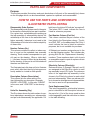
Purpose
This section provides illustrations and parts breakdown of all parts of the assembly(ies) shown
on the title page which can be disassembled, repaired or replaced, and reassembled.
HOW TO USE THE PARTS AND COMPONENTS
ILLUSTRATED PARTS LISTING
Disassembly Order System
The disassembly order system used in the parts
list shows the relationship of one part to another.
For a given item, replaceable parts making up
the top assembly or subassembly depicts the
relationship of the item to the associated next
higher assembly. Indenture is not used in this
illustrated parts list due to the relative simplicity
of these units.
Number Column (No.)
This column contains the callout or index number of a part on the exploded view assembly
drawing. Each number corresponds to a specific part on the drawing. When a triple dash
(---) is shown, the part is either the top assembly
for the drawing, or the part is not illustrated and
therefore not called out.
The illustrated parts list does not list or illustrate
parts which lose their identity by being permanently welded or riveted to other pieces.
Description Column (Description)
This column lists the noun name of the
item followed by any descriptor (Example:
GAUGE, LOW SIDE). In this case “GAUGE”
is the noun, and “LOW SIDE” is the descriptor.
Units Per Assembly (Qty)
The Qty column shows the total number of numbers required per assembly, per subassembly,
and per sub-subassembly as applicable. For
bulk items, the letters AR indicate “as required”.
The letters REF, if used, indicate the item is
listed for reference purposes.
Part Number Column (Part No.)
This column contains the part number of the
item listed in the Description column. The letters RNS, REF, or the abbreviated Ref. Only, if
used, indicate the item is listed for reference
purposes, but is not available for purchase.
A Robinair part number assigned a part is five
or six digit drawing number. Part numbers beginning with RA are “Replacement Assembly”
numbers. These numbers depict a kit of parts
or assemblies used to repair or replace certain
parts of the end item.
Effectivity Column (Effectivity)
Reference letters (A through Z except I and 0)
are assigned to the Effectivity column to each
top assembly in each IPL figure. The reference
letter of the applicable top assembly is also
shown in the Effectivity column for each detail
part and subassembly. When no reference letter is shown for detail parts and subassemblies,
the item is used on all top assemblies.
Parts Replacement Data
The interchangeability relationship between
parts is identified in the Description column of
the parts list. A list of the terms used to show
interchangeability and their definition is shown
in the table following.
89
P ar ts and C o m p o n e n t s
PARTS LIST
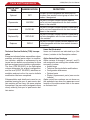
TERM
ABBREVIATION
Optional
OPT
Supersedes
SUPSDS
Superseded
SUPSD BY
Replaced By
REPLD BY
Replaces
REPLS
34788 (Basic) Service Manual
DEFINITION
This part is interchangeable with other parts in
the same Item number variant group or other item
number if designated
The part in the part number column replaces
and is not interchangeable with the item number
shown in the notation.
The part in the part number column is replaced by
and is not interchangeable with the item number
shown in the notation.
The part in the part number column is replaced by
and interchangeable with the item number shown
in the notation.
The part in the part number column replaces and
is interchangeable with the item number shown in
the notation.
Technical Service Bulletin (TSB) Incorporation
Except as indicated below, assemblies, subassemblies and detail parts subject to modification, deletion, addition or replacement by an
issued service bulletin are annotated to show
both pre and post service bulletin configuration.
column designates the original configuration,
semblies and parts after the service bulletin
modification has been completed.
Subassemblies and detail parts used on assemblies bearing the pre- or post-service bulletin notation will not carry the same notation
themselves if the use code(s) assigned to them
clearly reflect(s) their pre- or post-service bulletin status.
90
Items Not Illustrated
Items not illustrated are indicated by a (Not
shown.) notation in the Description column.
Alpha Variant Item Numbers
Alpha variants A through Z (except I and O)
are assigned to an existing item number when
necessary to show:
Added items
Technical Service bulletin modifications
Configuration differences
Optional parts
Product improvement parts (non service
bulletin)
Alpha variant item numbers are not shown on
the exploded view when the appearance and
location of the alpha variant item is the same
as the basic item.
Pa rt s and Co mp o n ents
34788 (Basic) Service Manual
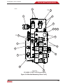
COMPONENT ASSEMBLIES
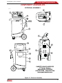
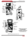
EXTERNAL ASSEMBLY
ss00426
6
1
2
3
4
7
5
8
12
9
13
11
10
14
15
16
PANZITTA SALES & SERVICE
72 George Avenue
Wilkes-Barre, PA 18705
570-822-6720 800-822-6720
www.panzittasales.com
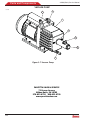
Figure 3-1. External Assembly
91
P ar ts and C o m p o n e n t s
34788 (Basic) Service Manual
EXTERNAL ASSEMBLY
No.
---
1
2
92
Description
UNIT, BASIC, 34788, 115 VAC (DOMESTIC)
UNIT, BASIC, 34788-1, 230 VAC
(INT’L ONLY)
UNIT, CORNWELL, RA-C34788, 115
VAC
UNIT, MATCO, H234788, 115 VAC
UNIT, MAC, AC34788, 115 VAC
UNIT, GENERAL MOTORS, GE48800, 115 VAC
UNIT, ROBINAIR, 48920, 115VAC
UNIT, BASIC, HONDA 48920T
UNIT, HONDA, 48920U, 115 VAC
UNIT, ROBINAIR, 34788-H, 115VAC
DECAL, 48920 CONTROL BOARD
DECAL, FRONT
Qty
---
1
1
Part No.
Ref. Only
Effectivity
A
Ref. Only
B
Ref. Only
C
Ref. Only
Ref. Only
Ref. Only
D
E
F
Ref. Only
Ref. Only
Ref. Only
Ref. Only
Ref. Only
539901
G
H
J
K
H, J
A, B, F, G, H,
J, K
C
D
E
A, B, F, G, K
C, D, E
H, J
3
FRONT PANEL ASSEMBLY
1
4
5
!"#$%&'*
BOTTLE, OIL DRAIN
5
1
124244
123867
124241
544023
544250
122293
121829
17756
6
BOTTLE, OIL DRAIN
CIRCUIT BREAKER, 15 AMP
1
1
121588
518638
7
8
9
CIRCUIT BREAKER, 7 AMP (INT’L
ONLY)
SWITCH, POWER, DPST (I/O)
DECAL, 1-800 PHONE NUMBER
CABLE, POWER
10
11
CABLE, POWER (INT’L ONLY)
DECAL, SERIAL NUMBER
STRAP, HOOK AND LOOP
552036
1
1
1
RA19343
109076
122770
1
1
545162
Ref. Only
121925
A, B, C, D, E,
F, G
H, J, K
A, C, D, E, F,
G, H, J, K
B
A, C, D, E, F,
G, H, J, K
B
Pa rt s and Co mp o n ents
34788 (Basic) Service Manual
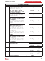
EXTERNAL ASSEMBLY
No.
12
Description
MANUALS, OPERATION
13
14
15
DECAL, 34724 FILTER REORDER
DECAL, UL
DECAL
16
DOOR, REAR, SIDEWINDER
EFFECTIVITY:
ROBINAIR 34788
ROBINAIR 34788-I
CORNWELL RA-C34788
MATCO H234788
MAC AC34788
GENERAL MOTORS GE-48800
ROBINAIR 48920
HONDA 48920T
HONDA 48920U
ROBINAIR 34788-H
Qty
1
1
1
1
Part No.
539680
539602
541844
541846
541845
539602
557701
560826
540600
Ref. Only
515770
1
121575
Effectivity
A, F
B
C
D
E
G
H, J
K
A, C, D, E, F,
G, H, J, K
A
B
C
D
E
F
G
H
J
K
PANZITTA SALES & SERVICE
72 George Avenue
Wilkes-Barre, PA 18705
570-822-6720 800-822-6720
www.panzittasales.com
93
P ar ts and C o m p o n e n t s
34788 (Basic) Service Manual
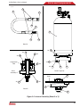
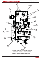
INTERNAL PARTS
ss00130
2
1
3
4
5
29 30
6
7
28
8
26 27
See
Detail A
24 25
14
See
18
Detail B
15 16 17
31
32
Front View
33 34
Side View
61 62 63
35 36 37
59 60
See
Detail C
38 39 40
58
57
41 42 43 44
54 55 56
53
45
52
46
See
Detail D
PANZITTA SALES & SERVICE
72 George Avenue
Wilkes-Barre, PA 18705
570-822-6720 800-822-6720
www.panzittasales.com
Rear View
Figure 3-2. Internal Assembly (Sheet 1 of 3)
94
Pa rt s and Co mp o n ents
34788 (Basic) Service Manual
ss00424
11
8
12
9
10
18
11
13
Detail A
2X 20
4X 48
49 4X
4X 50
4X 21
Compressor
Foot
51 4X
4X 22
Base
Assembly
23
19
Detail B (Typical)
36
Shelf
49 4X
4X 47
35
Detail D
Detail C
37
Figure 3-2. Internal Assembly (Sheet 2 of 3)
95
P ar ts and C o m p o n e n t s
34788 (Basic) Service Manual
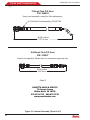
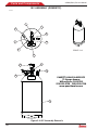
ss01291
Filtered Tank Fill Hose
P/N: 566452
Hose is not reparable, except for filter replacement.
R-134a Quick Seal Assembly, P/N 567796
44.381 inches
1127.28 mm
Unfiltered Tank Fill Hose
P/N: 539007
Hose is not reparable. Shown here for comparison purposes only.
42.00 inches
1066.8 mm
Detail E
PANZITTA SALES & SERVICE
72 George Avenue
Wilkes-Barre, PA 18705
570-822-6720 800-822-6720
www.panzittasales.com
Figure 3-2. Internal Assembly (Sheet 3 of 3)
96
Pa rt s and Co mp o n ents
34788 (Basic) Service Manual
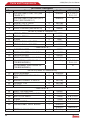
INTERNAL ASSEMBLY
No.
---
1
2
3
4
Description
UNIT, BASIC, 34788, 115 VAC (DOMESTIC) (SEE FIGURE 3-1 FOR
'*&+*;<=>?
UNIT, BASIC, 34788-1, 230 VAC
(INT’L ONLY) (SEE FIGURE 3-1 FOR
'*&+*;<=>?
UNIT, CORNWELL, H234788, 115
@;X&+[\"]X'
HIGHER ASSEMBLY.)
UNIT, MATCO, RA-C34788, 115 VAC
X&+[\"]X'*&+*ER ASSEMBLY.)
UNIT, MAC, AC34788, 115 VAC (SEE
X&+[\"]X'*&+*;SEMBLY.)
UNIT, GENERAL MOTORS, GE48800, 115 VAC (SEE FIGURE 3-1
X'*&+*;<=>?
UNIT, ROBINAIR, 48920, 115VAC
X&+[\"]X'*&+*ER ASSEMBLY.)
UNIT, BASIC, HONDA 48920T (SEE
X&+[\"]X'*&+*;SEMBLY.)
UNIT, HONDA, 48920U, 115 VAC
X&+[\"]X'*&+*ER ASSEMBLY.)
UNIT, ROBINAIR, 34788-H, 115VAC
X&+[\"]X'*&+*ER ASSEMBLY).
HEAD ASSEMBLY (SEE FIGURE 3-3
FOR BREAKDOWN.)
Qty
---
ENCLOSURE, HEAD HINGE COVER
ENCLOSURE HEAD, SHOULDER
!"#$%&'*
Part No.
Ref. Only
Effectivity
A
Ref. Only
B
Ref. Only
C
Ref. Only
D
Ref. Only
E
Ref. Only
F
Ref. Only
G
Ref. Only
H
Ref. Only
J
Ref. Only
K
2
Ref. Only
RA20080
Ref. Only
Ref. Only
539025-2
1
541750-2
539025-1
4
541750-1
121829
A, B, F, G
A, B, F, G, K
C, D, E
H, J
A, B, F, G, H,
J, K
C, D, E
A, B, F, G, H,
J, K
C, D, E
1
97
P ar ts and C o m p o n e n t s
34788 (Basic) Service Manual
INTERNAL ASSEMBLY
No.
5
6
7
8
9
10
11
12
13
14
15
16
17
18
19
20
21
22
23
24
25
26
27
28
29
30
98
Description
STATION PUMP, 3 CFM, 115V (SEE
FIGURE 3-7.)
STATION PUMP, 3 CFM, 230V (INT’L
ONLY) (SEE FIGURE 3-7.)
!"#$]&'*
BUSHING, HEYCO
HOSE, FLUSHING (SEE DETAIL A)
Qty
1
Part No.
RA20031
RA20075
3
1
1
Effectivity
A, C, D, E, F,
G, H, J, K
B
Ref. Only
100385
546946
DETAIL A (ITEMS 9 THROUGH 13)
FITTING, SPECIAL
1
546871
FITTING, SPECIAL
1
546872
O-RING
3
10267
FITTING, R134A, HIGH SIDE
1
546882
FITTING, R134A, LOW SIDE
1
546883
***END DETAIL A***
RUBBER BUMPER
1
122256
=;&!%&'*
1
123497
CENTER DIVIDER
1
545312
=;&!%&'*
7
123497
ISV ASSEMBLY (SEE FIGURE 3-4
1
Ref. Only
FOR BREAKDOWN.)
ISV ASSEMBLY (SEE FIGURE 3-5
FOR BREAKDOWN.)
DETAIL B (ITEMS 19 THROUGH 23)
SCALE ASSEMBLY
1
RA20002
=;*!"#$_
2
122255
INCH
WASHER, FENDER, ¼ INCH ID
4
Ref. Only
LOCKNUT, ¼-20
4
Ref. Only
MAGNET
1
539903
***END DETAIL B***
SHELF, VACUUM PUMP
1
545466
=;&!%&'*
2
123497
BOTTLE, OIL INJECT
1
115642
O-RING
1
112699
NUT, 8-32 SEMS
2
112414
PCB ASSEMBLY, RELAY BOARD
1
RA20070
RA20013
`"\#]z{&'*
4
Ref. Only
A, C, D, E, F,
G, H, J, K
B
A, B, C, D, E
A, B, C, D, E
OBSOLETE
Pa rt s and Co mp o n ents
34788 (Basic) Service Manual
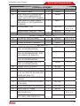
INTERNAL ASSEMBLY
No.
31
32
33
34
35
36
37
38
39
40
41
42
43
44
45
46
Description
TAG, POWER CABLE
HOSE, TANK FILL (FILTERED) SEE
DETAIL E FOR COMPARISON TO
539007 AND FILTER PART NUMBER.)
HOSE, TANK FILL (UNFILTERED)
(SEE DETAIL E FOR COMPARISON
TO 566452.)
FAN ASSEMBLY, 115V
Qty
1
1
Part No.
112661
566452
1
539007
1
RA17416
FAN ASSEMBLY, 230V (INT’L ONLY)
RA17516
]$"]`\z{&'*
2
122257
DETAIL C (ITEMS 35 THROUGH 37)
CAP, METAL, DRILLED, 38MM
1
RA19914
NUT, NYLON (PART OF RA19914)
1
522722
FITTING, STRAIGHT THROUGH
1
123616
***END DETAIL C***
MANIFOLD ASSEMBLY (SEE FIG1
RA20018
URE 3-6 FOR BREAKDOWN.)
MANIFOLD ASSEMBLY (SEE FIG530052
URE 3-6 FOR BREAKDOWN.) (EARLIER VERSION OF RA20018.)
MANIFOLD ASSEMBLY (SEE FIGRef. Only
URE 3-6 FOR BREAKDOWN.)
MANIFOLD ASSEMBLY (SEE FIG557696
URE 3-6 FOR BREAKDOWN.)
!"#$\"]z#&'*
1
Ref. Only
]z{]z#&'*
1
109556
DOOR LATCH KIT (CONTAINS ITEMS
2
RA19632
42, 43, 44.) (PART OF RA19916 FASTENER AND SEAL KIT.)
RETAINER, DOOR LATCH (PART OF
2
Ref. Only
RA19632)
RECEPTACLE, DOOR LATCH (PART
2
Ref. Only
OF RA19632)
LATCH, DOOR (PART OF RA19632)
2
Ref. Only
INSERT, DIE-CUT FOAM
1
541742
COMPRESSOR ASSEMBLY, 115V
1
RA20020
(SEE FIGURE 3-8.)
COMPRESSOR ASSEMBLY, 230V
RA20076
(INT’L ONLY) (SEE FIGURE 3-8.)
Effectivity
A, C, D, E, F,
G, H, J, K
B
A, B, C, D, E
A, B, C, D, E
A, B, C, D, E
A, B, C, D, E
A, B, C, D, E
F, G
H, J, K
A, C, D, E, F,
G, H, J, K
B
99
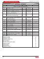
P ar ts and C o m p o n e n t s
34788 (Basic) Service Manual
INTERNAL ASSEMBLY
No.
Description
Qty
Part No.
DETAIL D (ITEMS 38 THROUGH 42)
47
LOCKNUT, ¼-20
4
Ref. Only
48
=;*!"#$#"&'*
4
119105
49
WASHER, FENDER, ¼ INCH ID
8
Ref. Only
50
SLEEVE, COMPRESSOR (PART OF
4
Ref. Only
RA20020 AND RA20076.)
51
GROMMET, COMPRESSOR (PART
4
Ref. Only
OF RA20020 AND RA20076.)
***END DETAIL D***
52
BASE ASSEMBLY (SEE FIGURE 9
1
544094
FOR BREAKDOWN.)
53
EDGE TRIM, RUBBER
A/R
Ref. Only
54
SENSOR ASSEMBLY
1
RA20086
55
BRACKET (PART OF RA20086.)
1
Ref. Only
56
NUT, 1/4 FLARE
1
113564
57
NUT, 8-32 SEMS
2
112414
58
|"\#\z|&'*<
1
514514
59
POWER SUPPLY, 12 VOLT
1
RA20014
60
SCREW, SOCKET HEAD CAP M3.5
4
RS-9100
}
61
SIDE SUPPORT ASSEMBLY
1
546620
62
=;&!%&'*
7
121829
63
WASHER, FLAT ¼ INCH
7
12719
EFFECTIVITY:
ROBINAIR 34788
ROBINAIR 34788-I
CORNWELL RA-C34788
MATCO H234788
MAC AC34788
GENERAL MOTORS GE-48800
ROBINAIR 48920
HONDA 48920T
HONDA 48920U
ROBINAIR 34788-H
100
Effectivity
H, J
H, J
A
B
C
D
E
F
G
H
J
K
Pa rt s and Co mp o n ents
34788 (Basic) Service Manual
HEAD ASSEMBLY
ss00135
1
3 2X
2
3 2X (See Note 1)
(See Note 2)
4
6
5
15
8
9
7
12
11
13
17
14
16
18
19
20
10
21
NOTES:
1. Torque Item 3 to 5 in-lbs.
2. Head Assembly shown is 34788 (Effectivity
codes A thru E); head assemblies for GE-48800,
34788-H, and 48920-series are similar except
for Oil Inject button (Effectivity codes F thru J).
4
Figure 3-3. Head Assembly
101
P ar ts and C o m p o n e n t s
34788 (Basic) Service Manual
HEAD ASSEMBLY
No.
---
8
Description
HEAD ASSEMBLY, BASIC (SEE
X&+[\"#X'*&+*;SEMBLY.)
HEAD ASSEMBLY, BRANDED (SEE
X&+[\"#X'*&+*;SEMBLY.)
HEAD ASSEMBLY, 48920T AND
{|~#$[X&+[\"#X'
HIGHER ASSEMBLY.)
GAUGE, LOW SIDE
GAUGE, HIGH SIDE
'[*]$"\#<
CABLE, INTERCONNECT
TUBE, 1/8 INCH RED, 4 FEET LONG
TUBE, 1/8 INCH BLUE, 4 FEET LONG
=]z|<
]z|&'*
'[MATIC
ENCLOSURE, SWIVEL TOP, FRONT
9
10
11
12
ENCLOSURE, SWIVEL TOP, FRONT,
RED
DECAL, OVERLAY
BEZEL (PART OF RA20001.)
<;*`"\#\z]`&'*
KEYPAD (RA20001 SHOWN)
1
2
3
4
5
6
7
13
14
15
16
17
102
PCB ASSEMBLY, DISPLAY/CONTROL
BOARD
`"\#\z|&'*
ENCLOSURE, SWIVEL TOP, BACK
ENCLOSURE, SWIVEL TOP, BACK,
RED
PCB ASSEMBLY, SD CARD, NGEN
RRR
*X<!"#$_
INCH PHD, PH
Qty
---
Part No.
RA20080
Effectivity
A, B, F, G, K
Ref. Only
C, D, E
Ref. Only
H, J
1
1
4
1
1
1
2
RA19786
RA19787
112415
539995
RA20003
RA20004
123928
1
539024-1
541749-1
1
1
6
1
539880
539618
515022
RA20001
1
557635
RA20012
4
1
539665
Ref. Only
539024-2
541749-2
1
539649
4
231728
A, B, F, G, H,
J, K
C, D, E
A, B, C, D, E,
F, G, K
H, J
A, B, C, D, E,
F, G, K
H, J
A, B, F, G, H,
J, K
C, D, E
Pa rt s and Co mp o n ents
34788 (Basic) Service Manual
HEAD ASSEMBLY
No.
18
19
20
Description
ENCLOSURE, SWIVEL, TOP, SIDE
COVER
ENCLOSURE, SWIVEL, TOP, SIDE
COVER, RED
`"]~_*
=;TITE
ENCLOSURE, SWIVEL TOP, POCKET
ENCLOSURE, SWIVEL TOP, POCKET, RED
21
CABLE, SD BOARD
22
;";
\"\z{\z\#&
23
DECAL, CONTROL PANEL, 34788
DECAL, CONTROL PANEL, 34788-I
DECAL, CONTROL PANEL, MAC
AC34788
DECAL, CONTROL PANEL, GE-48800
DECAL, CONTROL PANEL, 48920
EFFECTIVITY:
ROBINAIR 34788
ROBINAIR 34788-I
CORNWELL RA-C34788
MATCO H234788
MAC AC34788
GENERAL MOTORS GE-48800
ROBINAIR 48920
HONDA 48920T
HONDA 48920U
ROBINAIR 34788-H
Qty
1
Part No.
539024-3
541749-3
6
121711
1
539024-4
1
3
1
Effectivity
A, B, F, G, H,
J, K
C, D, E
541749-4
A, B, F, G, H,
J, K
C, D, E
539996
109695
540072
552110
541851
A
B
E
546987
Ref. Only
F
G, H, J, K
A
B
C
D
E
F
G
H
J
K
PANZITTA SALES & SERVICE
72 George Avenue
Wilkes-Barre, PA 18705
570-822-6720 800-822-6720
www.panzittasales.com
103
P ar ts and C o m p o n e n t s
34788 (Basic) Service Manual
ISV ASSEMBLY (DOMESTIC)
ss00136
1
2
8
3
7
4
LIQUID
V
SCALE: 1=4
6
SCALE: 1=4
5
11
10
12
9
VAPOR
AIR
PURGE
PANZITTA SALES & SERVICE
72 George Avenue
Wilkes-Barre, PA 18705
570-822-6720 800-822-6720
www.panzittasales.com
LIQUID
13
Figure 3-4. ISV Assembly Domestic
104
Pa rt s and Co mp o n ents
34788 (Basic) Service Manual
ISV ASSEMBLY, DOMESTIC
No.
---
1
2
3
4
5
6
7
8
9
10
11
12
13
Description
ISV ASSEMBLY, DOMESTIC (SEE
X&+[\"#X'*&+*;SEMBLY.)
TEMPERATURE PROBE
TRANSDUCER, AIR PURGE
TEE, MALE BRANCH 1/8 NPTF
ORIFICE, UNION, .026
<[XX=;&*;[
PRESSURE RELIEF, 450PSI
X&&'+?#}X
?#}X
.25MP
VALVE, BALL
FITTING, STRAIGHT
SOLENOID, 12VDC, DISCRETE
VALVE, BALL
VALVE, BALL
TANK, ISV
Qty
---
Part No.
Ref. Only
1
1
1
1
1
1
1
539472
RA20067
539654
539804
519605
RA20079
508690
1
1
1
1
1
1
540322
210312
RA20009
539799
539798
539477
Effectivity
All Domestic
Models
PANZITTA SALES & SERVICE
72 George Avenue
Wilkes-Barre, PA 18705
570-822-6720 800-822-6720
www.panzittasales.com
105
P ar ts and C o m p o n e n t s
34788 (Basic) Service Manual
ISV ASSEMBLY (INT’L)
SS00440
1
2
1
3
5
6
4
7
8
Figure 3-5. ISV Assembly (Int’l)
106
Pa rt s and Co mp o n ents
34788 (Basic) Service Manual
ISV ASSEMBLY, INTERNATIONAL
No.
--1
2
3
4
5
6
7
8
Description
ISV ASSEMBLY, INT’L (SEE FIGURE
\"#X'*&+*;<=>?
SOLENOID, 12VDC, DISCRETE
TEMPERATURE PROBE
VALVE, BALL
TRANSDUCER, AIR PURGE
<[XX=;&*;[
ORIFICE, UNION, .026
X&&'+]z|X
]z|X
1/8MP
TANK, ISV
Qty
---
Part No.
Ref. Only
1
1
1
1
1
1
1
RA20009
539472
544672
RA20067
519605
539804
508690
1
543184
Effectivity
All Int’l Models
107
P ar ts and C o m p o n e n t s
34788 (Basic) Service Manual
MANIFOLD ASSEMBLY
ss00437
3
2
4
5
4
6
2
1
Angle A
NOTE: When replacing Item 3 (19 on
models 48920T and U) or Item 6,
set Angle A and Angle B as closely as
possible to the original angle. Angles
may vary by model.
8
9
3
Angle B
10
Figure 3-6. Manifold Assembly (Sheet 1 of 5)
108
7
Pa rt s and Co mp o n ents
34788 (Basic) Service Manual
ss00142
12
11X 13
11
14
32
33 34 35
2X 18
12
17
15
12
3
3
16
12
Top View
(GE-48800, 34788-H, and Robinair 48920)
Figure 3-6. Manifold Assembly (Sheet 2 of 5)
109
P ar ts and C o m p o n e n t s
34788 (Basic) Service Manual
12
ss00141
12X 13
11
14
31
3
2X 18
12
17
15
12
3
3
16
12
Top View
(Robinair 34788, 34788-I, Cornwell H234788,
MATCO RA-C34788, and MAC AC34788)
Figure 3-6. Manifold Assembly (Sheet 3 of 5)
110
Pa rt s and Co mp o n ents
34788 (Basic) Service Manual
12
ss00438
13 12X
11
14
19
18
17
12
12
15
3
3
16
12
Top View
(Honda 48920T and 48920U)
Figure 3-6. Manifold Assembly (Sheet 4 of 5)
111
P ar ts and C o m p o n e n t s
ss00439
23
22
24
34788 (Basic) Service Manual
25
26
21
20
27
26
28
30
36
29
Figure 3-6. Manifold Assembly (Sheet 5 of 5)
PANZITTA SALES & SERVICE
72 George Avenue
Wilkes-Barre, PA 18705
570-822-6720 800-822-6720
www.panzittasales.com
112
Pa rt s and Co mp o n ents
34788 (Basic) Service Manual
MANIFOLD ASSEMBLY
No.
---
1
2
3
4
5
6
7
8
9
10
11
12
Description
MANIFOLD ASSEMBLY (SEE FIG[\"#X'*&+*;SEMBLY.)
MANIFOLD ASSEMBLY (SEE FIG[\"#X'*&+*;SEMBLY.)
MANIFOLD ASSEMBLY (SEE FIG[\"#X'*&+*;SEMBLY.) NOTE: MANIFOLD NO
LONGER AVAILABLE. NOT USED
AFTER 11-1-2008.
MANIFOLD ASSEMBLY (SEE FIG[\"#X'*&+*;SEMBLY.) NOTE: USED AFTER 11-12008.
MANIFOLD ASSEMBLY, 48920T
X&+[\"#X'*&+*ER ASSEMBLY.)
=]z|<
]z|
'[<;&
(SEE NOTE F.)
SOLENOID, 12VDC, DISCRETE (S13
AND S14)
=<
&']z|<
3/8 INCH PNEUMATIC (SEE NOTE F.)
X&&'+<
&']z|'
¼ INCH (SEE NOTE F.)
VALVE, CHECK (SEE NOTE E.)
TEE, MALE BRANCH, 1/8 NPTF(SEE
NOTE F.)
BALL, MANIFOLD PLUG (NOT
SHOWN.)
CAP, ¼ INCH FLARE W/O-RING(SEE
NOTES F AND G.)
VALVE CORE, SCHRADER (SEE
NOTE A.) (PART OF RA19916)
X&&'+!<X=]z|'
X
NOTE F.)
SWITCH, HIGH PRESSURE CUTOUT
VALVE, CHECK (75 IN-LB) (SEE
NOTE F.)
Qty
---
Part No.
RA20018
Effectivity
A, B, C, D, E
530052
A, B, C, D, E
Ref. Only
F, G, K
546621
F, G, K
557696
H.J
1
123928
2
RA20009
3
122950
2
122917
1
1
RA20015
539654
5
Ref. Only
1
111098
1
Ref. Only
1
100272
1
RA19427
7
6
RA20016
A, B, C, D, E
F, G, H, J, K
113
P ar ts and C o m p o n e n t s
34788 (Basic) Service Manual
MANIFOLD ASSEMBLY
No.
13
14
15
16
17
18
19
20
21
22
23
24
25
26
27
28
29
30
31
32
33
114
Description
SOLENOID, 12VDC, MANIFOLD (SEE
NOTE D.) (S1 THRU S12)
SOLENOID, 12VDC, MANIFOLD (SEE
NOTE D.) (S1, S2 AND S4 THRU S12)
X&&'+*;=X['&'?]#<
?#}
FL(SEE NOTE F.)
'']z|'
X]z|
'[MATIC (SEE NOTE F.)
TUBE, MANIFOLD CONNECTOR
(SEE NOTE C.)
SCREW, SOCKET HEAD (SEE NOTE
B.)
ACCUMULATOR TRANSDUCER
=<
&']z|'
X
¼ INCH (ON UNITS BUILT PRIOR TO
11-1-2008 WITH OIL INJECT.)
O-RING (SEE NOTE H.)
O-RING, CO873 2-240 (SEE NOTE
G.)
O-RING, PARKER P/N SB17-119-7N
(SEE NOTE G.)
O-RING, PARKER P/N SB17-143-7N
(SEE NOTE G.)
FILTER ELEMENT, COALESCING
BOWL, OIL SEPARATOR (SEE NOTE
A.)
['&']z|<
]z|<
?~
NOTE F.)
*;'+*;
SHELL, ACCUMULATOR
FILTER DRIER, SPIN ON
MANIFOLD BLOCK, LOWER
=<
&']z|'
1/4
PLUG, 1/8-27 NPTF SOCKET HD
(SEE NOTE F.) NOT SHOWN. (NONOIL INJECT UNITS ONLY.)
PLUG (NON-OIL INJECT UNITS
ONLY.)
Qty
12
Part No.
RA20010
Effectivity
A, B, C, D, E,
H, J
F, G, K
11
RA20010
2
100740
2
121771
1
537991
1
10001
2
1
RA20066
119984
2
1
18190
539668
1
123785
1
123786
1
1
123787
Ref. Only
2
101307
1
1
1
1
1
523477
Ref. Only
34724
Ref. Only
539544
A. B, C, D, E
1
Ref. Only
F, G, H, J, K
1
546609
F, G, H, J, K
A, B, C, D, E,
H, J
Pa rt s and Co mp o n ents
34788 (Basic) Service Manual
MANIFOLD ASSEMBLY
No.
34
Description
O-RING 016-NITRILE-70 (SEE NOTE
G.) NOT SHOWN. (NON-OIL INJECT
UNITS ONLY.)
35
O-RING 008 NITRILE-70 DUR (SEE
NOTE G.) NOT SHOWN. (NON-OIL
INJECT UNITS ONLY.)
36
MANIFOLD BLOCK, TOP
EFFECTIVITY:
ROBINAIR 34788
ROBINAIR 34788-I
CORNWELL RA-C34788
MATCO H234788
MAC AC34788
GENERAL MOTORS GE-48800
ROBINAIR 48920
HONDA 48920T
HONDA 48920U
ROBINAIR 34788-H
Qty
1
Part No.
10302
Effectivity
F, G, H, J, K
1
10265
F, G, H, J, K
1
Ref. Only
A
B
C
D
E
F
G
H
J
K
MANIFOLD ASSEMBLY NOTES
A. Torque Shrader valve core (item 14) and Oil Bowl Separator (item 25) to 1.5-3.0 IN-LB.
B. Torque to 30 IN-LB.
C. Apply Loctite 242 to threads of Manifold Connection Tube (item 16), then torque to 75 IN-LB.
D. Torque Manifold Solenoids (item 13) to manifold at 75 (±5) IN-LB.
E. Torque Check Valve (item 12) to 75 (±5) IN-LB; 6-places.
F. Apply Loctite 565 on all pipe threads.
G. Lubricate all O-rings on components before assembly.
115
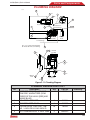
P ar ts and C o m p o n e n t s
34788 (Basic) Service Manual
VACUUM PUMP
ss00138
2
3
1
4
5
6
7
Figure 3-7. Vacuum Pump
PANZITTA SALES & SERVICE
72 George Avenue
Wilkes-Barre, PA 18705
570-822-6720 800-822-6720
www.panzittasales.com
116
Pa rt s and Co mp o n ents
34788 (Basic) Service Manual
VACUUM PUMP ASSEMBLY
No.
---
Description
VACUUM PUMP ASSEMBLY, 1.5
CFM, 115VAC
VACUUM PUMP ASSEMBLY, 1.5
CFM, 230VAC
VACUUM PUMP ASSEMBLY, 3 CFM,
115VAC
1
RESERVOIR ASSEMBLY (NOTE:
ITEMS 1 THRU 7 ARE FOR THE 3
CFM PUMP ONLY. 1.5 CFM PUMPS
DO NOT HAVE REPLACEMENT
PARTS. 1.5 CFM PUMPS MUST BE
ORDERED AS A COMPLETE UNIT.)
2
BRASS DISCHARGE FITTING (PART
OF ITEM 1)
3
BRASS INLET FITTING (PART OF
ITEM 1)
4
SIGHT GLASS NUT (PART OF ITEM
1)
5
OIL FILL PLUG (PART OF ITEM 1)
6
SIGHT GLASS ASSY W/O-RING
(PART OF ITEM 1)
7
OIL DRAIN ASSEMBLY W/CAP (PART
OF ITEM 1)
EFFECTIVITY:
ROBINAIR 34788
ROBINAIR 34788-I
CORNWELL RA-C34788
MATCO H234788
MAC AC34788
GENERAL MOTORS GE-48800
ROBINAIR 48920
HONDA 48920T
HONDA 48920U
ROBINAIR 34788-H
Qty
1
Part No.
RA20031
RA20075
RA20017
1
RA19950
1
Ref. Only
1
Ref. Only
1
Ref. Only
1
1
RA20019
Ref. Only
1
Ref. Only
Effectivity
A, C, D, E, F,
G, H, J, K
B
A, C, D, E, F,
G, H, J, K
A
B
C
D
E
F
G
H
J
K
117
P ar ts and C o m p o n e n t s
34788 (Basic) Service Manual
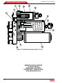
COMPRESSOR
ss00137
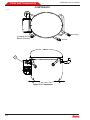
Discharge
Compressor Oil
Return (Suction)
Suction
1
Figure 3-8. Compressor
118
Pa rt s and Co mp o n ents
34788 (Basic) Service Manual
COMPRESSOR ASSEMBLY, 115 AND 230V
No.
---
Description
COMPRESSOR, 115V (DOMESTIC)
COMPRESSOR, 230V (INT’L ONLY)
1
ELECTRICAL SERVICE KIT, 115V
(INCLUDES THERMAL PROTECTOR,
START RELAY, CAPACITOR, CAPACITOR CAP, AND CAPACITOR LEADS.)
ELECTRICAL SERVICE KIT, 230V
(INCLUDES THERMAL PROTECTOR,
START RELAY, CAPACITOR, CAPACITOR CAP, AND CAPACITOR LEADS.)
EFFECTIVITY:
ROBINAIR 34788
ROBINAIR 34788-I
CORNWELL RA-C34788
MATCO H234788
MAC AC34788
GENERAL MOTORS GE-48800
ROBINAIR 48920
HONDA 48920T
HONDA 48920U
ROBINAIR 34788-H
Qty
---
Part No.
RA20020
--1
RA20076
RA20060
RA20061
Effectivity
A, C, D, E, F,
G, H, J, K
B
A, C, D, E, F,
G, H, J, K
B
A
B
C
D
E
F
G
H
J
K
PANZITTA SALES & SERVICE
72 George Avenue
Wilkes-Barre, PA 18705
570-822-6720 800-822-6720
www.panzittasales.com
119
P ar ts and C o m p o n e n t s
34788 (Basic) Service Manual
BASE ASSEMBLY
ss00144
1
6 2X
4 2X
3 2X
1
2X
2
2X 7
7X 8
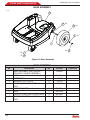
Figure 3-9. Base Assembly
BASE ASSEMBLY
No.
--1
2
3
4
5
6
7
8
120
Description
BASE ASSEMBLY (SEE FIGURE 1
X'*&+*;<=>?
BASE
COTTER PIN
WASHER, FLAT, .500 ID
WHEEL, PNEUMATIC, GRAY, 10
INCH
BUSHING, WHEEL
;=
;}&'*&;#&'*&
=;&!&'*]
INCH
Qty
1
Part No.
544094
1
2
2
2
Ref. Only
100723
102755
121841
2
1
2
8
Ref. Only
Ref. Only
RA19631
Ref. Only
Effectivity
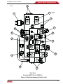
Pa rt s and Co mp o n ents
34788 (Basic) Service Manual
ELECTRICAL DIAGRAM
ss00149
Manifold
Assembly
ISV Assembly
Air Purge
Transducer
Accumulator
Transducer
Temperature
Probe
Low-Side
Transducer
S15 - Air
Purge
3
1
Scale
Assembly
4
J7
14
J11
J17
J13
J14
J8
Display/Control
Circuit Board
J5
S2 - HS Clear
S5 - HS Charge
S6 - LS Charge
S10 - Recover
S11 - Tank Fill
J18
J16
J9
J11
S1 - N Discharge
J6
J4
J1
13
SD Card
J1
S3 - Oil Inject
(when applicable)
S4 - DP Recover
S7 - HS Inlet
S8 - Vacuum
S9 - LS Inlet
S12 - Pwr Charge
S13 - Oil Return
S14 - Oil Drain
J2
HP Switch
5
J3
Vacuum
Pump
12
7
Power
Switch
J1
11
Circuit
Breaker
10
J2
12 Volt
Power
Supply
Compressor
9
8
Fan
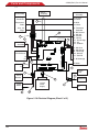
Figure 3-10. Electrical Diagram (Sheet 1 of 2)
121
P ar ts and C o m p o n e n t s
34788 (Basic) Service Manual
ss00444
Sensor
Assembly
ISV Assembly
Manifold
Assembly
Air Purge
Transducer
Accumulator
Transducer
2
Temperature
Probe
Low-Side
Transducer
S3 - Thermistor
Solenoid
S4 - DP Recover
S7 - HS Inlet
S8 - Vacuum
S9 - LS Inlet
S12 - Pwr Charge
S13 - Oil
S14 - Oil Drain
S15 - Air
Purge
3
1
15
4
J7
Scale
Assembly
J12
J11
J20
J13
J19
J17
J15
J5
J14
Display/Control
Circuit Board
J8
J10
J16
J9
J11
J21
S1 - N Discharge
J6
14
SD Card
J1
S2 - HS Clear
S5 - HS Charge
S6 - LS Charge
S10 - Recover
S11 - Tank Fill
J18
J4
J1
13
HP Switch
J3
J2
5
Vacuum
Pump
12
7
Circuit
Breaker
J1
12 Volt
Power
Supply
Power
Switch
11
J2
Compressor
9
8
10
Figure 3-10. Electrical Diagram (Sheet 2 of 2)
122
Fan
34788 (Basic) Service Manual
Pa rt s and Co mp o n ents
WIRING HARNESS DIAGRAM PARTS LIST
No.
1
2
3
4
5
6
7
8
9
10
11
12
Description
HARNESS, RELAY BOARD (J7, J8,
J13, J14) TO AIR PURGE, ACCUMULATOR, LOW SIDE TRANSDUCERS,
TEMPERATURE PROBE
HARNESS, VACUUM SENSOR (J15,
J19)
HARNESS, RELAY BOARD (J11) TO
\
+"{||$$\{||"*
AND 48920], S4, S7, S8, S9, S12,
S13, S14
HARNESS, RELAY BOARD (J17
AND J18) TO S2, S5, S6, S10, S11
CHARGE, S1 DISCHARGE, AND S15
PURGE (USED WITH THE RA20013
WHICH IS OBSOLETE.)
HARNESS, RELAY BOARD (J17
AND J18) TO S2, S5, S6, S10, S11
CHARGE, S1 DISCHARGE, AND S15
PURGE (FOR ALL CURRENT PRODUCTION, AND RA2000.)
HARNESS, RELAY BOARD (J4) TO
HIGH PRESSURE SWITCH
HARNESS, COMPRESSOR PIGTAIL
WIRE (64, 66, 76) T0 COMPRESSOR
START RELAY, THERMAL SWITCH,
GROUND THROUGH HARNESS
539991 (NOT SHOWN.)
HARNESS, COMPRESSOR TO HARNESS 539989
HARNESS, RELAY BOARD (J6) TO
VACUUM PUMP, FAN, AND COMPRESSOR THROUGH HARNESS
539991
HARNESS, RELAY BOARD (J2) TO
POWER SUPPLY (J1, J2)
CABLE, GROUND WIRE
POWER CABLE, 115VAC
POWER CABLE, 230VAC
HARNESS, RELAY BOARD (J1 AND
J3) TO POWER SWITCH AND CIRCUIT BREAKER
Qty
1
Part No.
539988
Effectivity
1
557700
H, J
1
539987
1
539927
549381
1
539992
1
544997
1
539991
1
539989
1
539994
1
1
539993
122770
1
545162
539990
A, C, D, E, F,
G, H, J, K
B
123
P ar ts and C o m p o n e n t s
34788 (Basic) Service Manual
WIRING HARNESS DIAGRAM PARTS LIST
No.
13
Description
HARNESS, DISPLAY/CONTROL (J11)
TO SD CARD (J1)
14
HARNESS, RELAY BOARD (J5) TO
DISPLAY/CONTROL PCB (J9)
15
HARNESS, RELAY BOARD (J16) TO
SCALE (PART OF SCALE ASSEMBLY
P/N 539853. SEE NHA, FIGURE 3-2.)
16
LEAD, CAPACITOR (NOT SHOWN.)
EFFECTIVITY:
ROBINAIR 34788
ROBINAIR 34788-I
CORNWELL RA-C34788
MATCO H234788
MAC AC34788
GENERAL MOTORS GE-48800
ROBINAIR 48920
HONDA 48920T
HONDA 48920U
ROBINAIR 34788-H
Qty
1
Part No.
539996
1
539995
1
Ref. Only
1
516844
PANZITTA SALES & SERVICE
72 George Avenue
Wilkes-Barre, PA 18705
570-822-6720 800-822-6720
www.panzittasales.com
124
Effectivity
A
B
C
D
E
F
G
H
J
K
Pa rt s and Co mp o n ents
34788 (Basic) Service Manual
PLUMBING DIAGRAM
ss00146
3
4 2X
7
6 2X
Vapor
8
Liquid
ISV Assembly
Vacuum Pump
1
Red Tube From
High Side Gauge
5
2
Manifold
Assembly
Blue Tube From
Low Side Gauge
Note: Use Locktite 242 Or Equivalent
On Threads Of All Hoses And Fittings
9 10
Oil Inject
Bottle
11
12 13
21 2X
Manifold
Assembly
14
15 2X
1.5
16
17 2X
Oil Drain
20
Bottle
18
Compressor
2X 19
Figure 3-11. Plumbing Diagram
PLUMBING DIAGRAM PARTS LIST
No.
---
1
2
3
4
Description
HOSE SET, SERVICE, HIGH AND
LOW SIDE, W/ADAPTERS (COMPRISED OF P/N 540331 [RED] AND
540332 [BLUE])
HIGH SIDE HOSE, RED
LOW SIDE HOSE, BLUE
VACUUM HOSE, LOW SIDE, TUB&'+!&'*$?${$&'*&
NUT, COMPRESSION, ¼ INCH TUBE
Qty
1
Part No.
37422
1
1
19”
540331
540332
120225
2
RA20007
Effectivity
125
P ar ts and C o m p o n e n t s
34788 (Basic) Service Manual
PLUMBING DIAGRAM PARTS LIST
No.
5
Description
VACUUM HOSE, HIGH SIDE, TUBING, 3/8 INCH HIGH PRESSURE
6
NUT, COMPRESSION, 3/8 INCH
TUBE
7
HOSE, ISV LIQUID
8
HOSE, ISV VAPOR
9
&=&'
[!&'*
0.040 INCH ID
10
NUT, COMPRESSION, ¼ INCH TUBE
11
HOSE, TANK FILL (FILTERED)
HOSE, TANK FILL (UNFILTERED)
12
@;[[<
[<
*;[[!
&'*$?${$&'*&
13
NUT, COMPRESSION, ¼ INCH TUBE
14
SUCTION TUBE, MANIFOLD TO
COMPRESSOR, 3/8 INCH HIGH
PRESSURE
15
NUT, COMPRESSION, 3/8 INCH
TUBE
16
DISCHARGE TUBE, COMPRESSOR
TO MANIFOLD
17
O-RING, NEOPRENE
18
COMPRESSOR OIL RETURN TUBE,
3/8 INCH HIGH PRESSURE
19
NUT, COMPRESSION, 3/8 INCH
TUBE
20
['>=']z|&'*?$$
ID (SEE FIGURE 6, ITEM 1 FOR
COMPRESSION FITTING.)
21
;";
|&'*='+?]|
THK
EFFECTIVITY:
ROBINAIR 34788
ROBINAIR 34788-I
CORNWELL RA-C34788
MATCO H234788
MAC AC34788
GENERAL MOTORS GE-48800
ROBINAIR 48920
HONDA 48920T
HONDA 48920U
ROBINAIR 34788-H
126
Qty
16”
Part No.
RA20005
1
RA20006
1
1
23”
541533
539068
120225
1
1
1
28”
RA20007
567272
539007
120225
1
15.5”
RA20007
RA20005
2
RA20006
1
538469
2
12”
RA19916
RA20005
2
RA20006
27”
121773
2
Ref. Only
Effectivity
A, B, C, D, E
A, B, C, D, E
A
B
C
D
E
F
G
H
J
K