1
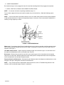
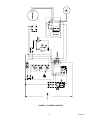
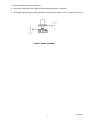
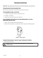
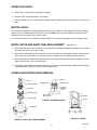
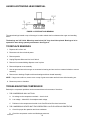
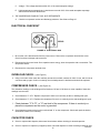
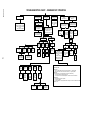
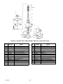
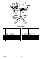
CMP 600-30 ICE MAKER DISPENSER Installation and Service Manual Part No. 630460050 11/7/97 THIS DOCUMENT CONTAINS IMPORTANT INFORMATION This Manual must be read and understood before installing or operating this equipment IMI CORNELIUS INC; 1997 PRINTED IN U.S.A TABLE OF CONTENTS Page SAFETY INFORMATION . . . . . . . . . . . . . . . . . . . . . . . . . . . . . . . . . . . . . . . . . . . . . . . . . . . . 1 RECOGNIZE SAFETY INFORMATION . . . . . . . . . . . . . . . . . . . . . . . . . . . . . . . . . . 1 UNDERSTAND SIGNAL WORDS . . . . . . . . . . . . . . . . . . . . . . . . . . . . . . . . . . . . . . . 1 FOLLOW SAFETY INSTRUCTIONS . . . . . . . . . . . . . . . . . . . . . . . . . . . . . . . . . . . . 1 SPECIFICATIONS . . . . . . . . . . . . . . . . . . . . . . . . . . . . . . . . . . . . . . . . . . . . . . . . . . . . . 3 INSTALLATION INSTRUCTIONS . . . . . . . . . . . . . . . . . . . . . . . . . . . . . . . . . . . . . . . . 3 ICEMAKER CLEANING AND SANITIZING PROCEDURES . . . . . . . . . . . . . . . . . 6 MAINTENANCE . . . . . . . . . . . . . . . . . . . . . . . . . . . . . . . . . . . . . . . . . . . . . . . . . . . . . . . 6 MONTHLY . . . . . . . . . . . . . . . . . . . . . . . . . . . . . . . . . . . . . . . . . . . . . . . . . . . . . . . . . . . . 6 QUARTERLY . . . . . . . . . . . . . . . . . . . . . . . . . . . . . . . . . . . . . . . . . . . . . . . . . . . . . . . . . . 6 SEMI–ANNUALLY . . . . . . . . . . . . . . . . . . . . . . . . . . . . . . . . . . . . . . . . . . . . . . . . . . . . . 6 WATER LEVEL CONTROL . . . . . . . . . . . . . . . . . . . . . . . . . . . . . . . . . . . . . . . . . . . . . . . . . 8 HOW WATER LEVEL CONTROL WORKS . . . . . . . . . . . . . . . . . . . . . . . . . . . . . . . . 8 PURPOSE OF WATER LEVEL CONTROL . . . . . . . . . . . . . . . . . . . . . . . . . . . . . . . . 8 TO REPLACE WATER LEVEL CONTROL . . . . . . . . . . . . . . . . . . . . . . . . . . . . . . . . 8 TO REPLACE WATER LEVEL SAFETY SWITCH . . . . . . . . . . . . . . . . . . . . . . . . . . 8 ICE LEVEL CONTROL . . . . . . . . . . . . . . . . . . . . . . . . . . . . . . . . . . . . . . . . . . . . . . . . . 8 REFRIGERATION SYSTEMS . . . . . . . . . . . . . . . . . . . . . . . . . . . . . . . . . . . . . . . . . . . . . . . 9 REFRIGERATION SYSTEM ADJUSTMENTS . . . . . . . . . . . . . . . . . . . . . . . . . . . . . 9 EXPANSION VALVE . . . . . . . . . . . . . . . . . . . . . . . . . . . . . . . . . . . . . . . . . . . . . . . . . . . 9 ADJUSTMENT AND TROUBLESHOOTING . . . . . . . . . . . . . . . . . . . . . . . . . . . . . . . 9 TEMPERATURE / PRESSURE CHARTS * . . . . . . . . . . . . . . . . . . . . . . . . . . . . . . . . . . . . 10 CONDENSER MODULATING VALVE (WATER COOLED ONLY) . . . . . . . . . . . . 10 CONDENSER MODULATING VALVE REMOVAL . . . . . . . . . . . . . . . . . . . . . . . . . . 10 GEAR MOTOR . . . . . . . . . . . . . . . . . . . . . . . . . . . . . . . . . . . . . . . . . . . . . . . . . . . . . . . . 11 TROUBLESHOOTING . . . . . . . . . . . . . . . . . . . . . . . . . . . . . . . . . . . . . . . . . . . . . . . . . . . . . . 12 TROUBLESHOOTING GEAR MOTORS . . . . . . . . . . . . . . . . . . . . . . . . . . . . . . . . . . 12 THE GEARMOTOR WILL NOT RUN . . . . . . . . . . . . . . . . . . . . . . . . . . . . . . . . . . . . . 12 THE GEARMOTOR STARTS BUTS TRIPS REPEATEDLY ON THE OVERLOAD PROTECTOR: . . . . . . . . . . . . . . . . . . . . . . . . . . . . . . . . . . . . . . . . . . . . . 12 THE MOTOR RUNS BUT OUTPUT SHAFT DOES NOT ROTATE: . . . . . . . . . . . 12 OVERLOAD CHECK: . . . . . . . . . . . . . . . . . . . . . . . . . . . . . . . . . . . . . . . . . . . . . . . . . . . 13 MOTOR CHECK: . . . . . . . . . . . . . . . . . . . . . . . . . . . . . . . . . . . . . . . . . . . . . . . . . . . . . . 13 INSTALLATION AND SHAFT SEAL REPLACEMENT) . . . . . . . . . . . . . . . . . . . . . . 13 AUGER & EXTRUDING HEAD REMOVAL . . . . . . . . . . . . . . . . . . . . . . . . . . . . . . . . 13 TO REPLACE BEARINGS . . . . . . . . . . . . . . . . . . . . . . . . . . . . . . . . . . . . . . . . . . . . . . 14 TROUBLESHOOTING COMPRESSOR . . . . . . . . . . . . . . . . . . . . . . . . . . . . . . . . . . . 14 ELECTRICAL CHECKOUT . . . . . . . . . . . . . . . . . . . . . . . . . . . . . . . . . . . . . . . . . . . . . . 15 OVERLOAD CHECK . . . . . . . . . . . . . . . . . . . . . . . . . . . . . . . . . . . . . . . . . . . . . . . . . . . 15 COMPRESSOR CHECK . . . . . . . . . . . . . . . . . . . . . . . . . . . . . . . . . . . . . . . . . . . . . . . . 15 CAPACITOR CHECK . . . . . . . . . . . . . . . . . . . . . . . . . . . . . . . . . . . . . . . . . . . . . . . . . . . 15 SAFETY CONTROLS . . . . . . . . . . . . . . . . . . . . . . . . . . . . . . . . . . . . . . . . . . . . . . . . . . 16 GUIDE TO GOOD ICE . . . . . . . . . . . . . . . . . . . . . . . . . . . . . . . . . . . . . . . . . . . . . . . . . . . . . . 17 i 630460050 TABLE OF CONTENTS (cont’d) Page TROUBLESHOOTING CHART – ICEMAKER NOT OPERATING . . . . . . . . . . . . . . . . 18 WARRANTY . . . . . . . . . . . . . . . . . . . . . . . . . . . . . . . . . . . . . . . . . . . . . . . . . . . . . . . . . . . . . . 24 LIST OF FIGURES FIGURE 1. WATER RESERVOIR . . . . . . . . . . . . . . . . . . . . . . . . . . . . . . . . . . . . . . . . 4 FIGURE 2 SCHEMATIC DIAGRAM . . . . . . . . . . . . . . . . . . . . . . . . . . . . . . . . . . . . . . 5 FIGURE 3. AUGER ASSEMBLY . . . . . . . . . . . . . . . . . . . . . . . . . . . . . . . . . . . . . . . . . 7 FIGURE 4. ADJUSTMENT SCREW . . . . . . . . . . . . . . . . . . . . . . . . . . . . . . . . . . . . . . 10 FIGURE 5. OUTPUT SHAFT . . . . . . . . . . . . . . . . . . . . . . . . . . . . . . . . . . . . . . . . . . . . 12 FIGURE 6. SHAFT SEAL REPLACEMENT . . . . . . . . . . . . . . . . . . . . . . . . . . . . . . . . 13 FIGURE 7. EXTRUDING HEAD . . . . . . . . . . . . . . . . . . . . . . . . . . . . . . . . . . . . . . . . . 13 FIGURE 8. AUGER . . . . . . . . . . . . . . . . . . . . . . . . . . . . . . . . . . . . . . . . . . . . . . . . . . . . 13 FIGURE 9. UPPER NUT AND BEARING . . . . . . . . . . . . . . . . . . . . . . . . . . . . . . . . . 14 FIGURE 10. ELECTRICAL BOX . . . . . . . . . . . . . . . . . . . . . . . . . . . . . . . . . . . . . . . . . 15 FIGURE 11. GEAR MOTOR THERMAL OVERLOAD . . . . . . . . . . . . . . . . . . . . . . . 16 FIGURE 12. REFRIGERATION FRAME ASSEMBLY CMP 600–30 (EXPLODED VIEW) AND PART LIST . . . . . . . . . . . . . . . . . . . . . . . . . . . . . . . . . . . . . 19 FIGURE 13. BIN AND FRONT END ASSEMBLY CMP 600–30 (EXPLODED VIEW AND PARTS LIST) . . . . . . . . . . . . . . . . . . . . . . . . . . . . . . . . . . . 20 FIGURE 14. ELECTRICAL BOX ASSEMBLY EXPLODED VIEW AND PART LIST . . . . . . . . . . . . . . . . . . . . . . . . . . . . . . . . . . . . . . 21 FIGURE 15. ICE LEVEL ASSEMBLY EXPLODED VIEW AND PARTS LIST PART NOT 31494–001 . . . . . . . . . . . . . . . . 22 FIGURE 16. DISPENSE MECHANISM ASSEMBLY EXPLODED VIEW AND PARTS LIST . . . . . . . . . . . . . . . . . . . . . . . . . . . . . . . . . . . . . 23 630460050 ii SAFETY INFORMATION Recognize Safety Information This is the safety-alert symbol. When you see this symbol on our machine or in this manual, be alert to the potentially of personal injury. Follow recommended precautions and safe operating practices. Understand Signal Words A signal word - DANGER, WARNING, OR CAUTION is used with the safety-alert symbol. DANGER identifies the most serious hazards. Safety signs with signal word DANGER or WARNING are typically near specific hazards. General precautions are listed on CAUTION safety signs. CAUTION also calls attention to safety messages in this manual. DANGER WARNING CAUTION Follow Safety Instructions Carefully read all safety messages in this manual and on your machine safety signs. Keep safety signs in good condition. Replace missing or damaged safety signs. Learn how to operate the machine and how to use the controls properly. Do not let anyone operate the machine without instructions. Keep your machine in proper working condition. Unauthorized modifications to the machine may impair function and/or safety and affect the machine life. CAUTION: Very high discharges pressure is present in system. Quick disconnects on your gages will minimize danger and loss of refrigerant. CAUTION: Unit requires separate electrical line. See instruction manual for proper fuse size. WARNING: There must be adequate clearance around ice maker. Allow minimum 6” air intake and 4” air exhaust for air exhaust and panel removal. NOTE: Unit must be installed per local plumbing and electrical codes. See Installation manual for unit requirements. Failure to do so may cause damage to unit, which would void unit warranty. NOTE: Using any parts other than genuine factory manufactured parts relieves the manufacturer of all liability. NOTE: Manufacturer reserves the right to change specifications at any time. 1 630460050 THIS PAGE LEFT BLANK INTENTIONALLY 630460050 2 SPECIFICATIONS Model Cond. Unit VAC Hz. Ph. Wire Comp. RLA Fan Amps GrmtrA mps CMP600–30A Air Cooled 115 60 1 2 12 1 2 Refrig. Oz. Type 28 Circuit Fuse R404A 20 INSTALLATION INSTRUCTIONS 1. REMOVE ICEMAKER FROM CARTON: A. Keep unit in the upright position, remove carton and pallet from unit and inspect unit for damage. Upon inspection of unit, if any damage is found, file a claim with carrier immediately. B. Locate Startup Card either on outside of container or on plastic liner. Fill in proper information and send one copy to factory, and other copy to Distributor. Postage is prepaid. 2. PREPARATION OF INSTALLATION SITE A. The refrigeration system on air cooled units requires airflow, so a well ventilated area should be chosen. A minimum of (6) inches must be maintained, free of any obstruction, for air intake. A minimum of (4) inches clearance is required for air exhaust. 3. WATER INLET HOOK–UP: A. Water Inlet – Fitting is a 1/4” SAE male flare located at the left rear bottom of the unit. Connect water supply with a 1/4”or larger copper or flexible tubing. B. Water Pressure – Unless otherwise specified, the unit is designed to operate on water pressures between 10 P.S.I. and 90 P.S.I. (NOTE: for pressures above 90 P.S.I. a regulator must be installed). C. Water Cooled Condensers D. a. Inlet to modulating valve uses 3/8” FPT. Use b. Outlet is 3/8” FPT. separate 3/8” or larger water line. Filters – Filter/Conditioners are recommended on supply lines to icemakers. Never run the water supply to water cooled Condenser through Filter/Conditioner, it uses up the cartridge unnecessarily and a saturated cartridge can starve the icemaker causing premature component damage. Separate water supplies are recommended. NOTE: Unit must be installed per local plumbing code. 4. ELECTRICAL SUPPLY A. Power Access – Is provided by way of a 7/8” dia. hole in the base. Route incoming power in conduit, to icemaker electrical control box. B. Make connections to wires provided in control box and ground lug/screw. Plug unused hole. C. Fused Line – Should be a dedicated circuit checked and sized according to electrical rating shown on unit nameplate. NOTE: Unit must be installed per local electrical code. 5. DRAIN CONNECTION A. Bin Drain– is a ” ID flexible tube located at the left bottom rear of the unit. Extend this line to proper drain. B. Overflow Line– is a 3/8” ID flexible tube located at the left bottom rear of the unit. Extend this line to proper drain. 3 630460050 6. AUGER ENGAGEMENT Be certain that auger is fully engaged to lower drive and that extruding head is fully engaged to evaporator. 7. INITIAL START UP, CHECKS & ADJUSTMENT INSTRUCTIONS NOTE: Do not start unit before completing Installation steps 1–6. Turn on water supply and main power switch (located on top of electrical box). Make the following system checks: NOTE: If unit will not start be sure water reservoir is full. Low water safety control must be properly adjusted to start and shut down unit. If water level drops below bottom of reservoir, unit must shut down. Adjustment is made by moving magnet up or down. FIGURE 1. WATER RESERVOIR Water Level – If necessary adjust Float by bending float arm up or down as needed, push float assembly down until unit stops running. Release float and unit will restart. Keep water in reservoir at level line while unit is in operation. See Figure 1. Low Water Safety Control – Adjust magnet by bending magnet arm as shown in figure 1 to shut down unit if the water level drops below the line on the side of the reservoir. Bin Control – Remove four screws from top of bin cover and lift cover so bin control plate can be manually lifted until unit shuts down. Release plate and unit will restart (NOTE: the dispense button must be depressed for 45 seconds before unit will start). Replace screws. Dispense Switch and Mechanism – By depressing the dispense switch, the dispense mechanism door on the storage bin will open, and agitator will rotate counterclockwise. NOTE: If any of these checks or adjustments cannot be achieved, refer to Troubleshooting Section of this manual or call our technical support center for assistance. 630460050 4 FIGURE 2. SCHEMATIC DIAGRAM 5 630460050 ICEMAKER CLEANING AND SANITIZING PROCEDURES Do not use any of the ice made during cleaning operations. Clean and sanitize ice storage area when cleaning icemaker. 1. Turn machine off. 2. Shut off water supply. 3. Remove ice from storage bin. 4. Mix approved cleaner (2 gallons as directed). Recommended cleaner: Calgon Corp. or Virginia Chemicals, ice machine cleaner. Mixture: 3-1/3 ounces per gallon water. Do not use nickel safe cleaners. 5. Turn machine on and add cleaner solution to water level control (float reservoir) until 2 gallons have been used. 6. Turn on water supply and run machine for 15 minutes. 7. Turn off machine. Remove and discard all ice. 8. Sanitize using household liquid bleach (50 PPM chlorine). Mixture: 1 fluid ounce per gallon room temperature water. 2 minute exposure time. 9. Sanitize pre-cleaned inside areas of storage bin liner, door frame, door, as well as exposed surfaces of the evaporator assembly and bin shutoff assembly with sanitizing solution and allow to air dry. MAINTENANCE PREVENTIVE MAINTENANCE CAN INCREASE THE TROUBLE FREE LIFE OF YOUR ICE MAKER. FAILURE TO PERFORM PREVENTIVE MAINTENANCE COULD VOID YOUR EQUIPMENT WARRANTY. Many authorized IMI Service Agencies offer service contracts. Contact your local distributor for further information. MONTHLY 1. Clean the condenser. Use a brush, vacuum cleaner or blow from inside with air or CO2 gas. If unit is provided with an air filter, clean or replace. 2. Inspect water feed reservoir at least once a month until a definite pattern for cleaning and sanitizing has been established. QUARTERLY This is the maximum period of time between cleaning and sanitizing the icemaker. In addition to recommended monthly procedure, and if a more frequent cleaning and sanitizing pattern has not been established, unit must be cleaned and sanitized quarterly. SEMI–ANNUALLY Semi–Annually in addition to all previously established service procedures perform the following: 1. Check for water leaks; tube connections, water fillings and lower icemaker water seal. 2. Check drain tubes for clogs and “aged” tubes. Replace if tubes are stained or brittle. 3. Check for signs of condensation. Clean where necessary and replace insulation properly. 4. Check safety circuits for proper operation. 630460050 6 5. Check refrigeration system (see Page 9). 6. Check unit for abnormal noise. Tighten machine and cabinet screws, if necessary. 7. Check white upper bearings on auger assembly. If bearings are less than 1/16” thick, replace See Figure 3. FIGURE 3. AUGER ASSEMBLY 7 630460050 WATER LEVEL CONTROL HOW WATER LEVEL CONTROL WORKS When water is introduced through the inlet fitting the float rises, the float pushes against a lever that in turn, forces the poppet assembly against the inlet fitting valve seat that seals the water off. See Figure 1. Before the water inlet is sealed, the safety switch is operated. In the event of a water failure the float would drop down and operate the safety switch to shut off the machine. If water level control will not shut off and seal at level as indicated, be sure inlet pressure does not exceed recommended factory operating range. Under ordinary circumstances adjustment should not be necessary providing it was properly adjusted when unit was installed or relocated. If however, the control becomes inoperative, repair or replace. See Start–up Adjustment page 3. PURPOSE OF WATER LEVEL CONTROL 1. To automatically maintain proper water level in the evaporator when the unit is running and making ice. 2. A safety switch is operated in the event of an interruption in water supply. The switch shuts off the electrical power to the icemaker and its refrigeration system. Switch will reset as soon as cause of water failure has been corrected and proper water level in icemaker has again been reached. 3. The transparent bowl not only provides a visible check of water level, but also is a good guide to the internal conditions which exist within the icemaker assembly itself. (See cleaning procedure.) TO REPLACE WATER LEVEL CONTROL 1. Shut off the water supply. Shut off the main power switch or unplug the ice dispenser from electrical outlet. 2. Remove the flexible tubing from bottom of water level control and drain water from water level control and evaporator. 3. Remove flexible tubing at bottom of water level bowl connected to the overflow. 4. Hold water inlet fitting with proper tool to prevent it from rotating when disconnecting the water inlet. 5. Remove wing nut holding water control to its mounting bracket. Control can be removed by lifting straight up. TO REPLACE WATER LEVEL SAFETY SWITCH 1. Shut off main power switch or unplug the ice dispenser from electrical outlet. 2. Unplug Molex connector connecting switch to electrical box. 3. Remove the 2 screws anchoring the water level safety switch to the bottom of the water level control mounting bracket. ICE LEVEL CONTROL The ice level control assembly is secured to the top of the ice storage container cover. The cover is secured to the storage container with four screws. The level control switch is operated by a plate assembly located beneath the diaphragm. When the plate assembly is down due to lack of ice in storage container, electrical impulse is sent to compressor, starting the ice making cycle. As ice level increases in storage container, the plate assembly is pushed up. When storage container is full, it deactivate the switch, stopping the compressor and ice making cycle. The operating positions of the switch is fixed, no adjustments are necessary. If switch replacement becomes necessary, simply disconnect cable at connector, remove wires from switch. 630460050 8 REFRIGERATION SYSTEMS REFRIGERATION SYSTEM ADJUSTMENTS A complete understanding of the icemaker and hermetic refrigeration system is necessary before any adjustments are made. The refrigeration technician must use high and low side pressure readings, water and air temperatures, plus general conditions of cleanliness to assess the refrigeration system status when making any adjustments. All icemaker products are tested and adjusted at the factory prior to shipment where the ambient temperature ranges from 65_F to 90_F, depending on the season of the year. Whenever a new icemaker is initially installed and started–up, it is imperative that the start–up operator make the following checks and readjustments for local conditions. EXPANSION VALVE You will find a thermal expansion valve on Wilshire ice makers, which is used to control the amount of refrigerant flowing through the evaporator. Improperly installed or defective expansion valves may cause low production, soft ice, squeaking from evaporator and excessive load inside evaporator. By using general refrigeration trouble shooting along with the pressure charts, you can easily determine whether or not the expansion valve is working properly. ADJUSTMENT AND TROUBLESHOOTING When troubleshooting the expansion valve, you must; 1. Be sure you have adequate water flowing into the evaporator, a clean and properly ventilated condenser, and the system is properly charged and free of any restrictions. Also be sure compressor is operating properly. 2. Take reservoir water temperature and air temperature from condenser inlet and determine at what pressure unit should be running. On machines equipped with thermostatic valve there is NO adjustment. If correct pressure cannot be obtained, be sure system has time to stabilize, 10–15 minutes. 3. Be sure sensing bulb is located at outlet side of evaporator about 3–4 inches away from evaporator and be sure to insulate well and clamp tightly to tubing. If system pressures are still not adequate, take a second water and air temperature reading and go over other parts of the system for possible problems. If proper charge is questionable evacuate and recharge to nameplate and leak check. If valve still malfunctions replace valve. Use general refrigeration system practices when replacing and recharging unit. After new valve is in place, go through previous monitored adjustments and troubleshooting to be sure valve is functioning properly. NOTE: valve. On water cooled units adjust condenser modulating valve before troubleshooting expansion CAUTION: Very high discharge pressure is present in system. Quick disconnects on your gages will minimize Danger and loss of refrigerant. Comply with federal regulations for reclaiming refrigerant. 9 630460050 TEMPERATURE / PRESSURE CHARTS * CMP600–30 Refrigerant Type R404A ± 10 lb. Discharge Pressure Water Temperature Air Temp. 40 65 50 174 177 60 202 205 70 230 233 80 265 269 90 300 304 100 328 334 NOTE: The thermostatic expansion valve is non–adjustable on CONDENSER MODULATING VALVE 90 180 208 236 272 307 340 all models (Water Cooled Only) The reason for using a water modulating valve is to supply the correct amount of water to the condenser to maintain the proper operating pressure in the refrigeration system high side. The flow of water through the valve is increased as the high side pressure rises and decreases as high side pressure lowers. FIGURE 4. ADJUSTMENT SCREW To calibrate the amount of water flow with the refrigeration system high side pressure, turn adjustment screw located on end of valve opposite of bellows See Figure 4. Turn screw counterclockwise to raise opening point. Opening point of valve should be set to maintain proper operating pressure in refrigeration system high side. Refer to Pressure Chart on Page 10. Closing point of valve should be set low enough to close valve during compressor stand by periods. NOTE: Cold water will absorb more heat faster than warm water. The water flow will therefore automatically increase as inlet temperature increases. CONDENSER MODULATING VALVE REMOVAL 1. Disconnect power to unit, then shut off water supply to condenser and reclaim refrigerant from system. 2. Remove inlet water line from Condenser modulating Valve. Also remove tube from refrigerant high side line. 630460050 10 3. Remove Condenser Modulating Valve and bracket from unit. 4. Remove valve from bracket. 5. Replace Condenser Modulating Valve by reversing Steps 2 thru 4. Then pull system into vacuum. 6. Recharge unit with refrigerant per nameplate. 7. Turn power and water On to unit. 8. With unit running adjust modulating valve to proper setting. 9. Go through a complete system check. GEAR MOTOR The gear motor is equipped with a start relay and a manual reset overload. When current is applied, the relay energizes and completes the circuit to the start winding. The motor reaches a predetermined speed and the relay drops out, disconnecting the start winding. The run winding remains in the circuit as long as current is applied. The purpose of the overload is to automatically shut off the motor in the event of a mechanical bind of the transmission, an overload condition within the evaporator or an electrical malfunction. It does this by sensing amperage draw. If the motor stalls the start relay would energize and stay energized. The amperage would surge to 5 to 6 times greater than normal draw. In this event the overload would shut off the transmission in 4 to 8 seconds. If the motor is subjected to an abnormal load, but does not reach stall condition, the overload will react, but over a greater period of time. The reaction time depends upon the amperage to which it is subjected. The overload, through the safety circuit, also shuts off the compressor. Refer to Troubleshooting Guide. 11 630460050 TROUBLESHOOTING IMPORTANT: Only qualified personnel should service internal components or electrical wiring. TROUBLESHOOTING GEAR MOTORS Basically, Gear motor problems can be narrowed down to three areas of checkout. THE GEARMOTOR WILL NOT RUN 1. No voltage to the transmission terminals – check external circuit. 2. Low voltage – check supply. 3. Problems in the gear motor electrical circuit. See Figure 5 THE GEARMOTOR STARTS BUTS TRIPS REPEATEDLY ON THE OVERLOAD PROTECTOR: 1. Voltage – high or low voltage can cause the overload to trip. 2. High Gear motor amperage draw, see Specification Chart for ratings and Troubleshooting Guide. FIGURE 5. OUTPUT SHAFT THE MOTOR RUNS BUT OUTPUT SHAFT DOES NOT ROTATE: 1. Replace defective gear motor. CAUTION: Be sure unit is disconnected from the power source. Disconnect the transmission cable. 630460050 12 OVERLOAD CHECK: 2. Allow motor to cool and reset overload if necessary. 3. Remove motor end bell and stator, if necessary. 4. Check terminals 1 and 3 on overload. No continuity replace overload. Use a volt–ohm meter. See Figures 5 and 6. MOTOR CHECK: The resistance readings on the windings will be between 5 to 25 ohms. A meter capable of these low readings must be used. The Start Relay cover must be removed. NOTE: Gear motor and related components can be checked from Pin Connector. See Figures 5 and 6. If no continuity on start or run winding test, replace stator. If continuity on grounded motor test, replace stator. INSTALLATION AND SHAFT SEAL REPLACEMENT (See Figure 6) 1. Place shaft seal locator seat over gear motor output shaft, embossed side down, and push down until shaft seal seat rests flush on top of gear motor. 2. Place rubber coated ceramic seal (important: ceramic face up) over output shaft and push down until seal rests on top of the shaft seal seat. (Lubricate rubber on ceramic seal with [#06195] rubber lubricant.) 3. Place shaft seal with carbon face down(spring up) over output shaft and push (gently) downward until seal rests on carbon face of the output shaft seal. 4. Push down on the washer compressing the spring on the output shaft seal. While holding the seals (down) in place slide the E–ring into the groove on the output shaft. AUGER & EXTRUDING HEAD REMOVAL AUGER NUT E–RING BEARING DELRIN BEARING NYLON WASHER, PLAIN FLAT GROOVE EXTRUDING HEAD SHAFT SEAL MOUNT, SHAFT SEAL ANTI–ROTATION RIB– 3 PLACES AUGER SEAT, SHAFT SEAL FIGURE 7. EXTRUDING HEAD “D” DRIVE GEARMOTOR FIGURE 8. AUGER FIGURE 6. SHAFT SEAL REPLACEMENT 13 630460050 AUGER & EXTRUDING HEAD REMOVAL FIGURE 9. UPPER NUT AND BEARING The upper bearings located on top of the auger is used to absorb the force between the auger and extruding head. The bearings are 3/32” thick. When they wear below 1/16” they should be replaced. Bearings to be inspected for wear during quarterly maintenance. See Figure 9. TO REPLACE BEARINGS 1. Dispense all ice from unit. 2. Disconnect unit from electrical power. 3. Remove panels. 4. Unplug Dispense Motor and Ice Level Switch. 5. Remove four screws holding dispense cover in place. 6. Remove dispense cover assembly. 7. Use an open end wrench on auger nut connected to bearing and turn and turn counterclockwise to remove assembly. 8. Remove worn bearings. Replace with new bearings and then reinstall assembly. NOTE: If auger turns with nut, remove cover on top of gear motor stator and hold rotor while loosening nut. 9. Reconnect power to icemaker. TROUBLESHOOTING COMPRESSOR Basically the compressor problems can be narrowed down to three areas of checkout– 1. THE COMPRESSOR WILL NOT RUN A. No voltage to the compressor terminals – check circuit. B. Low voltage – below 90% of nameplate rated voltage. C. Problems in the compressor electrical circuit. See Electrical Checkout instructions. 2. THE COMPRESSOR STARTS BUT TRIPS REPEATEDLY ON THE OVERLOAD PROTECTOR A. Check for proper fan operation and clean condenser. B. Check the compressor suction and discharge pressures. 14 630460050 C. Voltage – The voltage should be within 10% of the rated nameplate voltage. D. High compressor amperage draw, it should never exceed 120% of the rated nameplate amperage. See Electrical Checkout Instructions. 3. THE COMPRESSOR RUNS BUT WILL NOT REFRIGERATE A. Check the compressor suction and discharge pressures. See Chart on Page 10. ELECTRICAL CHECKOUT FIGURE 10. ELECTRICAL BOX 1. Be sure the unit is disconnected from the power source. Remove the compressor electrical box cover. Check for obvious damage and loose wires. 2. Disconnect the fan motor leads. Since capacitors store energy, short the capacitor with a screwdriver. This will prevent shocks. 3. Disconnect the compressor terminal wires. OVERLOAD CHECK – (See Figure 5) 4. Using a volt–ohm meter check the continuity across the overload, contacts #1 & #3. If none, wait for unit to cool down and try again. If still no continuity, the overload protector is defective and should be replaced. COMPRESSOR CHECK – (See Figure 10) The resistance readings on the windings will be between 0.25 and 10.00 ohms, a meter capable of these low readings must be used. 5. Check between ”C” & ”R.” Replace compressor if there is no continuity as the run windings are open. 6. Check between ”C” & ”S.” Replace the compressor if there is no continuity as the start windings are open. 7. Check between ”C” & ”R”, or ”S” and shell of the compressor. If there is continuity replace the compressor as the motor is grounded. 8. Check between screw terminal on the overload and ”C” on the compressor. Check and repair the lead or connections if there is no continuity. CAPACITOR CHECK 9. Check or replace start capacitor, disconnect bleed resistor before checking for shorted capacitor. 10. Check or replace run capacitor (if supplied) check or shorted capacitor or either terminal grounded to case. 630460050 15 SAFETY CONTROLS FIGURE 11. GEAR MOTOR THERMAL OVERLOAD Your Icemaker unit has several safety and control devices incorporated into its design. WARNING: None of the below described devices should ever be ”bypassed” to allow the unit to function. The safety and control system shut–off devices are: 1. Low water shut off reed switch located in icemaker float assembly. (Automatic reset type). 2. Gear motor thermal overload, manual reset type (red button on motor). See Figure 11. 3. Compressor thermal overload, automatic reset type. 4. Main service switch located on top of the control box. 5. Hopper shut–off. 6. High pressure cut out (water cooled only). WARNING: Do not reset gear motor overload if ice is present in the evaporator. 630460050 16 GUIDE TO GOOD ICE CUSTOMER COMMENTS It runs but the ice is too soft. The icemaker is not producing enought ice. The ice is too wet. CHECK ICEMAKER LOCATION CONDITIONS FIRST Under compression Proper air flow for condensing system Location too close to high temp units such as coffee urns, deepfryers, grills etc. Supply water conditions. Water too warm (above 90_F) CHECK ICEMAKER Use gages for checking suction and head pressures. See manual for correct reading and conditions. Check water level for proper adjustment and restrictions. See Manual. Check evaporator assembly for worn parts, bearings, scored evaporator and, bad expansion valve, etc. Water artificially softened above 262 PPM sodium chloride. Normal water supply too high. It makes too much noise. (with this comment the ice is usually extremely hard and larger thant normal). Over Compression Obstructions partially blocking ice exit from top of evaporator. Check to see if nois objection objections is normal fan and air flow noise. Check fan and fan shroud. Water supply conditions. Check for loose parts and screws rattling. Water too cold (below 50_F) (Possibly running from Pre-cooler). 17 Check evaporator assembly for worn parts, bearings, scored evaporator and auger, bad expansion valve etc. 630460050 630460050 TROUBLESHOOTING CHART – ICEMAKER NOT OPERATING ICEMAKER RUNS BUT DOES NOT MAKE ICE NO POWER LOW WATER SAFTEY SWITCH OPEN –Check bin switch –Check to see if ice control plate moves freely Condenser fan runiing but compressor not running –Check electrical wiring in control box for loose connections –Check for failed service switch or relay –Check power to machine –Check line voltage –Check compressor winding & components –Check that wateris turned on –Check for restriction in water line –Check incoming water pressure (minimum 10 lbs.) –Check water saftey switch Evaporator water tube may have an air bubble. Clear air bubble from tube High suction pressure (30 lbs. or above) Non–condensibles in system Too much refrigerant in system 18 Evacuate and recharge system. Clean condenser Low on refrigerant Check for leaks Condenser fan not running Condenser dirty or restricted Plugged liquid line dryer Replace drier. Evacuate and recharge system TXV bulb lost charge Valve stuck open Bulb loose Bulb uninsulated Replace valve evacuate and recharge Restricted liquid line Plugged or faulty TXV Icemaker froze up Check for kinks or damage to liquid line Replace valve evacuate and recharge system Check if auger is turning Check drive on gearmotor Refer to ”Guide to Good Ice” in Service manual GEARMOTOR OVERLOAD TRIPPED Check water level control and evaporator water tube for lime build up restriction No CAUTION Clear ice from evaporator and auger before resetting overload Yes CLEAN See instructions Reset overload Icemaker runs IMPORTANT Icemaker runs when reset but problem has not been found. Continue checking for overload as follows to guard against future problems Short run trips again in 2 minutes. Check gearmotor circuit Resets but motor does not run Check gearmotor circuit Will not reset Overload hot try again Will not reset replace overload OVERLOAD GUIDE ELECTRICAL: – High or low voltage Weak power lines can cause overloads on icemaker restarts – High running current. Check motor circuits and start relay – Auger delay failed ICEMAKER: – Mechanical parts worn. Scored evaporator or auger. Worn thrust bearing – Ice maker not turning off. Failed ice level control – Over compession. Low water inlet temperature. Restriction in water line from reservior REFRIGERANT: – Contaminated charge or bad compressor. – Low charge or gas leak – Low suction pressure. Improper expansion valve sensing bulb location or insulation and/or defective expansion valve No Check gears in gearbox No Low suction presure (20 lbs. or below) Suction line not insulated Clean and insulate – Check bin switch – Check to see if ice control plate moves freely Clean all related drain lines TXV not operating properly Clean and tighten ICEMAKER OPERATING BUT – Soft ice – Poor dispensing Yes Head pressure high Replace valve – Check electrical circuit to fan motor – Check fan motor STORAGE CONTAINER BIN SWITCH OPEN Check if extruding head is down in evaporator tube 9 7 5 8 14 2 11 1 18 10 FIGURE 12. REFRIGERATION FRAME ASSEMBLY CMP 600–30 (EXPLODED VIEW) AND PART LIST Item No. 1 2 3* 4* 5 6* * * 7 8 9 10 Part No. Name 638004204 638036272 638004285 630900310 638004391 638004643–04 638008646 638008943 638033058 638031108 638031110 638031494 638031715–03 Condenser – (Air Cooled) Condenser – (Water Cooled) Shroud – Fan Fan Blade Bracket–Fan Mounting Water Level Control Fan Motor Asm. (115V) Exhaust Fan (Water Cooled Units) Mounting Bracket, Exhaust Fan Dispense Mechanism (115V) Storage Bin Ice Level Control (115V) Electrical Box Asm. (115V) Item No. Part No. 11 12* 638090630 638090021 13* 14 15* 16* 17* 18 638009755 638090221 638090222 638090224 638090223 638004303 Name Front End Asm. 600–30 (115V) Valve, Water Regulating (Water Cooled) Pressure Switch (Water Cooled) Compressor(115V) Start Relay(115V) Start Cap(115V) Run Cap(115V) Drier * = Not shown 19 630460050 20 21 NO TAG 22 6 19 5 1 18 16 4 15 17 8 2 14 NO TAG 13 3 7 12 11 10 9 8 7 26 27 24 25 23 NO TAG 25 FIGURE 13. BIN AND FRONT END ASSEMBLY CMP 600–30 (EXPLODED VIEW) Item No. Part No. Name 1 2 3 4 5 6 7 * 8 9 10 11 12 13 14 638031110 638031108 638007201–03 630200331 638031017 161179001 638090050 638011645 638090215 638031027 638090051 638007301–030 638090053 638090216 16883300 Storage Bin Assembly Dispense Mechanism (115V) Nut #8–32 ESNA Clip, Retainer Retainer Ring Screw 1/4–20 X 3/4 HHMS Gear motor (115V) w/ item2 9–14 Cable Asm, Gear Motor, 5–Wire,115V Shaft Seal Mount O–Ring 3/16 X 1 1/2 Seal–Shaft Mechanism Washer Lower E – Ring Shaft Seal Seat Washer–Lock, 1/4 Split 630460050 20 Item No. Part No. 15 16 17 18 19 20 21 22 23 24 25 26 27 28 16117901 638031719–001 638090226 638031021 638090213 638090211–002 638090219 638090217 638095111 638004442 638031517 638007972–03 638000845 638090220 Name Screw, 1/4–20 X 3/4 Lg. Evaporator Assembly Expansion Valve Gasket, Hopper/Evaporator Auger, D–Drive Auger Nut Bearing–Nylon Extruding Head Assembly ISO–Pad Spacer Bracket Front End Assembly Screw #10 X 3/4 Type”B” HHWF Washer Flat Bearing–Delrin 15 13 17 16 6 12 NO TAG9 5 20 NO TAG 4 14 3 8 10 NO TAG 1 NO TAG19 18 NO TAG 7 2 FIGURE 14. ELECTRICAL BOX ASSEMBLY EXPLODED VIEW AND PART LIST Item No. Part No. 1 2 3 4 5 6 7 8 9 10 638031001 638090052 638031003 638033044 638004791 638003611 638007030–08 63807030–02 638007214 638007204–02 Name Electrical Box Contactor, 3 Pole, (115V 60Hz) Capacitor, Run (115V Only) Insulation Boot Switch, Toggle Bushing, Universal Screw, #8 X 3/4” Screw, #6–32 X 1/4” Nut, 15/32–32 Hex Lock Nut, #6–32 Keps 21 Item No. Part No. 11 12 13 14 15 16 17 18 19 20 21* 638031084 638007904–03 638007903–01 638007948–01 638007902–01 638007904–01 638007904–05 638004792 638007303–04 638007214 638031498 Name Cover Electrical Box (IMD600–30) Housing–2 Circuit Recept. Red Housing–3 Circuit Recept. Housing–4 Circuit Recept. Housing–6 circuit Recept. Housing–2 Circuit Recept. Housing–2 Circuit Recept. Blue Indicator Plate Lock Washer Nut Auger Delay (115V) 630460050 8 16 6 2 3 10 11 NO TAG7 1 3 5 13 9 15 17 14 20 12 14 NO TAG 18 FIGURE 15. ICE LEVEL ASSEMBLY EXPLODED VIEW AND PARTS LIST PART NOT 31494–001 Item No. Part No. 1 2 3 4 5 6 7 8 9 10 11 12 638031077 63831493–001 63807264–02 63831011 63831156 63811396 63807308–01 63807009–10 63831010 63831014 63807337–02 63831078 630460050 Item No. Description Bracket Switch Mounting Dispense Motor Asm. (115V) Nut Tinnerman Twin Bracket Switch Switch Ice Level Bin Control Cable Washer Fiber Screw #6–32 X 1–1/4” Rod, Actuator Spring Return Retainer ”E”–Ring Agitator Arm 13 14 15 16 17 18 19 20 21 22 Part No. 63831150 63807088–03 63807002–03 63801026 63807069–02 63807301–18 63807051–02 63831159 63831076 63831075 Description Diaphragm Screw, 1/4–20 X 1/2” Screw, #6–32 X 3/8 Strain Relief Screw, #10–32 X 1–1/4” Washer Screw, #10–32 X 3/8” Upper Agitator Arm Top Cover, Inside Top Cover, Outside 12 9 11 13 10 15 14 8 1 5 4 7 5 3 2 3A FIGURE 16. DISPENSE MECHANISM ASSEMBLY EXPLODED VIEW AND PARTS LIST Item No. Part No. 1 2 3 A 4 5 6 7 638031035 638010081 638007051–02 638007304–01 638031007 638007337–02 638000981 638031006 Name Bracket, Solenoid Mounting (115V) Solenoid (115V) Screw, #10–32 X 3/8” Washer, #10 Ext. Tooth Lock Pin, Linkage Retainer, ”E”–Ring Spacer Linkage (115V) 23 Item No. Part No. 8 9 10 11 12 13 14 15 638004443 638004417 638031096 638004416 638007338–01 638031036 638031002 638004418 Name Spring, Torsion Lower Pin, Drive Insulation, Door Pin Pivot Retainer Ring Door Gasket, Door Spring, Torsion Upper 630460050 IMI CORNELIUS INC. ONE CORNELIUS PLACE ANOKA, MN. 55303–6234 TELEPHONE (800) 238–3600 FACSIMILE (612) 422–3232 TECH SVC 1-800-535-4240 WARRANTY IMI Cornelius Inc. and Remcor Products Company warrants that all equipment and parts are free from defects in material and workmanship under normal use and service. For a copy of the warranty applicable to your Cornelius and or Remcor product, in your country, please write, fax or telephone the IMI Cornelius office nearest you. Please provide the equipment model number, serial number and the date of purchase. IMI Cornelius Offices AUSTRALIA D P.O. 210, D RIVERWOOD, D NSW 2210, AUSTRALIA D (61) 2 533 3122 D FAX (61) 2 534 2166 AUSTRIA D AM LANGEN FELDE 32 D A-1222 D VIENNA, AUSTRIA D (43) 1 233 520 D FAX (43) 1-2335-2930 BELGIUM D BOSKAPELLEI 122 D B-2930 BRAASCHAAT, BELGIUM D (32) 3 664 0552 D FAX (32) 3 665 2307 BRAZIL D RUA ITAOCARA 97 D TOMAS COELHO D RIO DE JANEIRO, BRAZIL D (55) 21 591 7150 D FAX (55) 21 593 1829 ENGLAND D TYTHING ROAD ALCESTER D WARWICKSHIRE, B49 6 EU, ENGLAND D (44) 789 763 101 D FAX (44) 789 763 644 FRANCE D 71 ROUTE DE ST. DENIS D F-95170 DEUIL LA BARRE D PARIS, FRANCE D (33) 1 34 28 6200 D FAX (33) 1 34 28 6201 GERMANY D CARL LEVERKUS STRASSE 15 D D-4018 LANGENFELD, GERMANY D (49) 2173 7930 D FAX (49) 2173 77 438 GREECE D 488 MESSOGION AVENUE D AGIA PARASKEVI D 153 42 D ATHENS, GREECE D (30) 1 600 1073 D FAX (30) 1 601 2491 HONG KONG D 1104 TAIKOTSUI CENTRE D 11-15 KOK CHEUNG ST D TAIKOKTSUE, HONG KONG D (852) 789 9882 D FAX (852) 391 6222 ITALY D VIA PELLIZZARI 11 D 1-20059 D VIMARCATE, ITALY D (39) 39 608 0817 D FAX (39) 39 608 0814 NEW ZEALAND D 20 LANSFORD CRES. D P.O. BOX 19-044 AVONDALE D AUCKLAND 7, NEW ZEALAND D (64) 9 8200 357 D FAX (64) 9 8200 361 SINGAPORE D 16 TUAS STREET D SINGAPORE 2263 D (65) 862 5542 D FAX (65) 862 5604 SPAIN D POLIGONO INDUSTRAIL D RIERA DEL FONOLLAR D E-08830 SANT BOI DE LLOBREGAT D BARCELONA, SPAIN D (34) 3 640 2839 D FAX (34) 3 654 3379 USA D ONE CORNELIUS PLACE D ANOKA, MINNESOTA D (612) 421-6120 D FAX (612) 422-3255 630460050 24 IMI CORNELIUS INC. Corporate Headquarters: One Cornelius Place Anoka, Minnesota 55303-6234 Telephone (800) 238-3600 Facsimile (612) 422-3246


![Service Manual VA13 Carbonator [ 002818 ]](http://vs1.manualzilla.com/store/data/006013608_1-0f8f87056a0ab013b1dd01dac3912d47-150x150.png)