1
INSTALLATION INSTRUCTION AND SERVICE MANUAL
Actuator/Trailer Dealer - Please provide these instructions to the consumer.
Consumer - Read and follow these instructions. Keep them with the trailer for future reference.
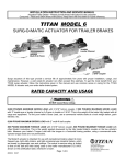
TITAN MODEL 60 SURG-O-MATIC
ACTUATOR FOR TRAILER BRAKES
INTRODUCTION TO SURGE BRAKING
Surge braking is accomplished by replacing a trailer's standard tongue coupler with an actuator and adding hydraulic brake
assemblies. The "surge" or "push" of the trailer toward the tow vehicle during deceleration < automatically synchronizes these
trailer brakes with the tow vehicle brakes. As the trailer pushes against the vehicle, the actuator telescopes together and applies
force to its master cylinder, supplying hydraulic pressure to the trailer brakes.
Surge actuators of this type provide a service life of approximately five years with proper installation, usage, and maintenance.
However, a well cared-for actuator can often exceed this estimate. To get the most benefit from your TITAN surge actuator,
follow the instructions given in this manual and use common sense in caring for the MODEL 60 and your entire trailer brake
system.
RATED CAPACI TY AND USAGE
!!WARNING!!
Do not exceed these ratings.
6,000 POUNDS MAXIMUM GROSS LOAD (weight of trailer fully loaded with all cargo and equipment). To find your trailer's
Gross Load, use a commercial vehicle scale at a truck weigh station, grain elevator, etc.
600 POUNDS MAXIMUM TONGUE LOAD (weight applied downwards by the fully loaded trailer's coupler onto the tow vehicle's
hitch). Measure your trailer's Tongue Load with the tongue in the horizontal towing position, using either a commercial scale or a
bathroom scale if the load is small enough. Upwards tongue loads are not permissible.
The MODEL 60 actuator is intended for light occasional use on recreational, marine, and baggage trailers, which are towed by
passenger cars or pickups. The actual in-service rating is limited to that of the ball and hitch being used or the trailer
manufacturer's G.V.W.R. shown on the certification label, whichever is lower. The actuator will provide enough fluid displacement
to supply up to four TITAN free-backing or uni-servo drum style trailer brakes.
Page 1 of 12
!!WARNING!!
DO NOT submerge the actuator. Internal corrosion may result and cause brake failure. Salt water, granular fertilizers, and
other corrosive materials are destructive to metal. To minimize the damaging effect of corrosion on a braking system used
under corrosive conditions, we recommend that the actuator be externally flushed after use with a high pressure water
hose. Be sure to lubricate all moving parts after the unit has dried. Whenever the unit will be out of service for an extended
period of time, or after hard use, remove the brake drums and clean inside the brakes. Pack wheel bearings with grease
before the drum is installed. Failure to properly and adequately grease and maintain the actuator could weaken it an d/or
cause it to fail and result in serious injury and/or property damage.
INSTALLATION*
1.
The MODEL 60 Actuator is completely assembled and ready to bolt into place onto straight three inch wide trailer tongues.
WELDING IS NOT RECOMMENDED since it will make repair or replacement di fficult, destroy the plated or painted surface
finish, and could potentially cause internal damage resulting in decreas ed brake performance. If the actuator must be painted for
aesthetic reasons, TITAN recommends painting ONLY the outer case, and disassembling the unit prior to painting. Application
of heavy coats of paint may interfere with component operation. Confirm the coupler and break-away mechanisms work properly
before operation. Store actuators indoors and in their original shipping carton until the time of installation.
2.
Bolt the actuator to the tongue using 1/2 inch by 4 inch grade 5 bolts, nuts, and lock washers. The two holes match standard
coupler mounting holes on three inch wide trailer tongues, as shown in Figure 1. light weight tongues require spacer tubes
inside for reinforcement such as a 3/4 inch outside diameter by eleven gauge piece of tubing. Using a torque wrench, tighten
bolts to eighty (80) foot-pounds torque.
3.
Install the hydraulic brakes and brake lines on the trailer as described in the installation manual supplied with the brakes. DO
NOT crush or kink the tubing as you mount the actuator. TITAN recommends 3/16 inch brazed double wall tubing per
S.A.E. J527 for us e with all our actuator and brake products. Use forty-five degree (45°) double-flare tube ends per S.A.E.
J533. DO NOT remove or modify the ori fice connector <17> at the rear of your actuator's master cylinder. It connects
directly to the brake tubing and ensures proper fluid flow characteristics.
4.
After installation of the actuator, brake, and brake lines as described above, proceed immediately to the "BRAKE FLUID
FILLING AND BLEEDING" instructions.
!!WARNING!!
Failure to complete the "BRAKE FLUID FILLING AND BLEEDING" procedures promptly after
installation may result in internal master cylinder corrosion and cause brake failure.
*NOTE: <#> Is the reference number shown in the assembly diagram of the actuator located at the end of this
manual.
Page 2 of 12
BRAKE FLUID FILLING AND BLEEDING
!!WARNING!!
Use only fresh brake fluid from a sealed container. DO NOT reuse fluid. After filling and bleeding,
remember to refill the actuator. Failure to maintain an adequate fluid level may cause brake failure.
1.After completing the “INSTALLATION" instructions, remove the master cylinder's cap <20> and fill the reservoir to
three-quarters full with DOT-3 brake fluid. DO NOT allow brake fluid to contact painted surfaces since it will damage
the finish. Wipe up any spills immediately and wash the area with water.
2. Bleed the brake system either manually or with a pressure bleeder. Pressure bleeding equipment simplifies the
process, and is available at your local automotive supply store. Use the instructions provided with the pressure
bleeder. If you chose to manually bleed the system, an assistant makes the job easier. Use the following steps to
manually bleed the brake system:
A. Fill the master cylinder with fluid as described above. Repeatedly press the tip of the push rod assembly <14>. This
can be done by inserting a screwdriver in the round hole on the top of the coupler case <3>. Use the screwdriver
as a lever to press the push rod. Apply short stroke s until bubbling stops inside the master cylinder.
!!WARNING!!
DO NOT use the actuator's break-aw ay lever or cable to bleed the brake system.
B. Install a bleeder hose on the bleeder screw of the farthest wheel cylinder from the actuator. If the trailer has
tandem axles, bleed the rear axle first. Submerse the other end of the hose in a glass container of brake fluid, so
that air bubbles can be observed.
C. Open the bleeder screw and have your helper stroke (but not release) the push rod <14>. Brake fluid and/or air
bubbles will flow into the jar. Close the bleeder screw. The helper can then allow the push rod to return.
D. Repeat the process until no more bubbles are released with the stroke. Air trapped in the brake lines will greatly
reduce your braking efficiency. Be sure to close the bleeder screw securely when the cylinder is fully bled.
E. Repeat the bleeding operation at each wheel cylinder. During the bleeding process, replenish the master
cylinder reservoir's brake fluid so that the level does not fall below half full. This
. will ensure that no air is drawn
into the system.
3.
After all brakes have been bled, again make sure that the master cylinder reservoir is filled to three-quarters full
before operating. Check that the filler cap gasket is not torn or damaged. Screw the filler cap and gasket into the
master cylinder cover. The filler cap only needs to be finger tight.
TES TING TI TAN SURGE BRAKE SYSTEMS
!!WARNING!!
It should be noted that the field-test procedure indicates only if the trailer brake system is functional, but
DOES NOT provide information on how efficiently it w ill operate. Regular inspection, maintenance, and
adj ustment of all brake system components (including the surge actuator, tubing, hoses, brake clusters,
drums, and associated hardware/support structure) are still required to ensure maximum brake
performance and smooth, even brake operation.
1.
Hydraulic surge actuator systems provide automatic and smooth trailer braking without special application by the
tow vehicle driver. While this is extremely convenient it can sometimes be difficult to determine if the surge setup
is functioning properly. The following steps provide a quick field-test to confirm that the trailer brake system is
operational.
*NOTE: <#> rs the reference number shown in the assembly diagram of the actuator located at the end of this manual.
Page 3 of 12
2.
Move the trailer to flat, level ground, pulling FORWARD several
feet before parking. This forward motion will ensure trailers
equipped with free-backing brakes are in their normal operating
mode. Disconnect the trailer from the tow vehicle and j ack the
trailer's tongue until it is horizontal.
3.
Hook the trailer's s afety chains (NOT the actuator's break-away
cable/chain) together to form a loop, which is centered below the
actuator's coupler as shown in Figure 2.
4.
Place a sturdy board, such as a 2 inch by 4 inch piece of lumber,
into the chain loop below the coupler. The
board should be 4 feet or longer so it will extend several feet above the actuator. Keep the end of the board a few inches off t he
ground, and position it to press against the front end of the actuator's coupler.
5.
Stand in front of the trailer and face the rear. Apply force to the top end of the board to use it as a l ever. Press back towards t he
rear of the trailer. The board will begin moving the coupler case (inner slide) into the actuator's outer housing.
6.
Keep pressing the top of the board to stroke the actuator and its internal master cylinder. If the trailer brake system is operational,
the brak es will apply and keep the trailer from rolling away from you. Properly adjusted uni-s ervo duo-servo type brakes will
prevent you from moving the trailer back more than a few inches. Free-backing type brakes will initially provide rolling
resistance, but continued force on the board will switch them into free-backing mode, and you'll be able to move the trai ler
backwards.
7.
If you have uni-servo or duo-s ervo brakes, and stroking the actuator (as described above) caus es the trailer to roll away from you
freely or with only minimal resistance, the brakes are NOT applying properly. If you have free-backing brakes, and stroking the
actuator (as described above) causes the trailer to roll away without initial resistance, the brakes are NOT applying properly. The
brake system MUST be evaluated to determine the cause of the problem, and corrective action MUST be taken before the trai ler
is used.
8.
Use this procedure each time you tow your trailer to check your surge brake system operation.
HITCHING TRAILER
!!WARNING!!
To ensure proper engagement of the actuator's coupler to the tow ball, DO NOT use a multi-piece ball, an
incorrectly sized ball, or a worn/damaged ball.
1.
Confirm the towing hitch and ball have a rating equal to or greater than the trailer G.V.W.R. and are properly and s ecurely
attached to the tow vehicle. The hitch MUST be installed so the trailer tongue is level (horizontal) when coupl ed to the tow
vehicle.
2.
To attach the actuator to the tow vehicle, follow the procedure below which corresponds to your actuator's coupler type.
A. MULTI-FIT COUPLER:
The multi-fit (hand wheel) coupler will accept 1-7/8 inch, 50 millimeter, and 2 inch diameter tow balls. Open the coupler by
depressing the hand wheel lock <27> and turning the hand wheel <28> fully counterclockwise until its rotation is stopped by
the lock ring <29>. Lower the coupler onto the ball, confirming that the ball is fully seated in the coupler socket. Tighten the
hand wheel in a clockwise direction to secure the ball. The hand wheel lock should click as you turn the hand wheel, to
confirm that the hand wheel will stay tightened. Turn the hand wheel until it can no longer be turned by hand, and then back
it off until the lock cat ches in the nearest not ch on the bottom of the hand wheel. Check that the ball latch <25> has been
drawn up snugly under the tow ball, trapping it in the coupler socket. Do not tow the trailer if the coupler is damaged.
*NOTE: <#> Is the reference number shown in the assembly diagram of the actuator locat ed at the end of this manual.
Page 4 of 12
B.
LEVER-LOCK
COUPLER:
The lever-lock coupler is preset at the TITAN factory to fit 2" trailer balls. It can be adjusted to fit 1-7/8 inch or
50 millimeter diameter tow balls by tightening the coupler's locknut <9>, which is underneath the ball latch
<25>. After adjustment, make sure that the sides of the locknut is trapped between the flanges of the lock plate
<24> so that the locknut can not vibrate loose during trailering. Open the coupler by pressing the handle
assembly's <32> lock trigger so it unhooks from the lock plate's loop, and then by swinging the handle forward.
Lower the coupler onto the ball, confirming that the ball is fully seated in the coupler socket. Swing the handle
upwards until the lock trigger hooks onto the lock plate loop to secure the ball. Check that the ball latch <25>
has been drawn up snugly under the tow ball, trapping it in the coupler socket, and that the lock trigger is firmly
hooked onto the lock plate loop. A properly adjusted lever-lock coupler will have between 1/64 inch and 1/32
inch of free play between the ball and ball socket. Do not tow the trailer if the coupler is damaged.
Check that the actuator's coupler is securely latched onto the tow ball by extending the trailer's tongue jack to the
ground. Use it to lift the trailer tongue and tow vehicle hitch two to four inches. The coupler and ball should remain
engaged. DO NOT tow the trailer unless the coupler is latched onto the ball securely. Retract the trailer tongue j ack
before towing.
4. The coupler mechanism may be further secured by following the procedure below which corresponds to your actuator's
coupler type.
A. MULTI-FIT COUPLER:
Confirm that the tow ball is fully secured in the coupler as previously described. Insert a standard padlock through
the holes in the side of the hand wheel <28>. The padlock will stop against the bracket on top of the couple case
<3> and further prevent the hand wheel from rotating and opening. Do not use padlocks which interfere with the
telescoping action of the actuator and thereby compromise braking performance.
B. LEVER-LOCK COUPLER:
Confirm that the tow ball is fully secured in the coupler as previously described. With the handle in the locked
CMI!) position, insert either a standard padlock or spring pin through the hole in the side of the handle assembly
<32>. This will lock the handle to the handle bolt and further prevent the handle assembly from swinging forward
and opening. Do not use padlocks or pins which interfere with the telescoping action of the actuator and thereby
compromise braking perform ance.
5.
As shown in Figure 3, your tow vehicle's hitch provides a safety
chain hole or ring on each side. Attach your trailer's safety chains
securely to these connection points, being sure to cross the chains
UNDER the trailer tongue. Safety chains MUST be used. This will
prevent the trailer tongue from dropping to the road if the coupler
separates from the tow vehicle's hitch. If your tow vehicle's hitch
does not provide safety chain connection points, have appropriate
ones added by a reputable hitch installer.
!!WARNING!!
The trailer safety chains' length MUST be set short enough so the actuator's break-away cable is NOT pulled if the
coupler separates from the tow vehicle's hitch but remains connected by the safety chains. The breakaway syst em
should only be activated after BOTH the trailer's coupler AND safety chains have failed and allowed the trailer to
completely separate from the tow vehicle. Provide just enough slack in the trailer safety chains to allow tight turns.
The chains should not drag on the ground. Safety chains must be used.
6.
Attach the actuator's break-away cable S-hook <11> securely to one of the tow vehi cle hitch's safety chain connection points.
Confirm that the trailer's safety chains are adjusted relative to the actuator's break-away cable as noted previously. DO NOT loop
the break-away cable around a bracket and hook it back onto itself.
7.
Before towing, check that the break-away lever assembly <10> is properly positioned as shown on the cover illustration of this
manual.
*NOTE: <#> Is the reference number shown in the assembly diagram of the actuator located at the end of this
manual.
Page 5 of 12
!!WARNING!!
The break-away system is not designed to operate if the trailer does not separate completely from the tow vehicle, or if the
trailer tongue "submarines" and goes beneath the tow vehicle. DO NOT use the break-away system as a parking brake.
8.
If the break-away lever and cable are not located correctly, due to either the cable being pulled during use or by accident, it
MUST be reset prior to the trailer being moved.
!!WARNING!!
An incorrect lever or cable position may cause the trailer brakes to drag and overheat, or may keep the brakes from being
applied in a break-away situation. After any usage of the break-away mechanism, either real or accidental, check all system
components (lever, cable, S-hooks, cover, pin, push rod assembly, etc.) for damage. Replace any damaged items with
genuine TITAN service parts.
Resetting is accomplished by first removing the two screws <31> which retain the cover over the break-away spring <13>. This
will allow the cover to be li fted. By pulling the break-away lever <10> slightly further forward, you'll be able to pry the breakaway spring carefully out of the notch in the outer case <1> to release the break-away lever. When removing the break-away
spring, be careful not to deform it.
!!WARNING!!
The hydraulic pressure held in the system may cause the lever and push rod assembly to snap back quickly. Keep hands and
fingers clear as you reset the break-away mechanism.
Inspect all break-away system components for damage. Replace any
damaged items with genuine TITAN service parts. With the break-away
spring removed, the lever can now be returned to its original position. Check
that the tip of the break-away lever which is inside the outer case <1 >, is in
FRONT of the push rod ass embly <14>. Also confirm that the roll-pin,
which is pressed through the break-away lever, has remained inside the
outer cas e. Following Figure 4, reinsert the break-away spring into the outer
case notch, with the spring flange in the lever's upper detent groove. Replace
the cover and fasten it securely with the two screws.
If the hydraulic pressure being held in the system is too great to permit the
break-away spring to be easily pried out, it can also be released by removing
the front roller bolt <8>. This will allow the front of the coupler case <3> to
swing down and free the break-away lever. The break-away spring can then
be pried out
_
and reset as des cribed above. Be sure to reassemble the rollers <7> with their chamfered
ends out against the walls of the coupler
case <3>. Tighten the locknuts <9> on the roller bolts <8> just to zero free-pl ay between the outer case <1> and the coupler case
<3>, and then back the locknuts off one-hal f turn. Overtightening will restrict proper surge operation.
9.
Weight distributing (equalizing) hitches have been an important part of trailering for many years. They shift excess tongue
weight from the end of the tow vehicle by distributing it across all vehicle and trailer axles. Leveling the tow vehi cle and t he
trailer reduces the stress on the suspension components and increases towing stability.
All TITAN surge brake actuators are fully compatible with equalizing hitches. When using weight distributing hitches with
TITAN actuators, observe the following rules:
1)
Allow six to eight inches of free chain length,
2)
The chains must be vertical (straight up and down) under pulling load, and
3)
Tongue weight beyond the specifi ed actuator rating WILL interfere with brake performance.
*NOTE: <I> Is the reference number shown in the assembly diagram of the actuator located at the end of this manual.
Page 6 of 12
The above statem ent summarizes TITAN's three "rules of thumb" for equalizer/actuator compatibility. Each rule contributes to
optimum trailer braking.
RULE #1: Allow six to eight inches of free chain length. This means that the equalizer's chains must be at least six to eight inches
long between the spring bars and the hook-up brackets (whi ch attach the chains to the trailer). Surge brake actuators must be free
to compress their internal master cylinder. Shorter lengths of chain will limit the distance the actuator can move, and this restricts
the unit's braking.
RULE #2: The chains must be vertical (straight up and down) under pulling load. During towing, these chains must be aligned
straight up and down. This should be confirmed on l evel ground with the trailer coupled (using the equalizing hitch) to the t ow
vehicle. After checking that the actuator is in its towing position (not compressed), adjust the position of the hook-up brackets on
the trailer until the chains are vertical. If the chains are angled forward or back on the TITAN actuator, they have a t endency to
either impede the braking action by limiting the distance the actuator can stroke or prematurely apply the brakes by pulling the
trailer forward rel ative to the tow vehicle.
RULE #3: Tongue weight beyond the speci fied actuator rating WILL interfere with brake performance. Weight distributing
hitches spread tongue weight over the axles of both the tow vehicle and the trailer by applying leverage against the trailer tongue
and actuator/coupler. This additional force and torque on the trailer system approximat ely doubles the load on the actuat or,
potentially exceeding its load rating.
For example, a fully-loaded trailer with a hitched tongue weight of 250 pounds might be equipped with a TITAN Model 60
actuator. A weight distributing hitch would then cause the actuator to receive the equivalent of a 500 pound tongue load. Since
500 pounds is less than the TITAN Model 60 actuator's 600 pound tongue load rating, this set-up would be accept able. If a
similar trailer has a 350 pound tongue weight, and once again an equalizer is hooked up, the actuator would perceive a 700 pound
tongue load. That would put the system above the 600 pound tongue load rating of the actuator. Since the excess tongue load on a
surge actuator can cause it to stroke less freely (resulting in less effective braking), this would be an inappropriate set-up.
Two factors in selecting towing equipment are gross trailer weight (GTW) and tongue load (TL). GTW is the weight of the trailer
fully loaded in its actual towing condition. This can be measured by pl acing the fully loaded trailer on a vehicle s cale. TL is the
downward force exerted on the trailer hitch ball by the trailer coupler. In most cases it is 10% to 15% of the GTW.
10. Sway control devices that restrict operation of the actuator CANNOT be used. The actuator MUST be free
to telescope in response to braking requirements.
!!WARNING!!
When towing, AVOID sharp turns which can cause the actuator to bind against the tow vehicle. This can damage th e
actuator and trailer, causing brake failure. AVOID towing across severe bumps or dips which may cause the tow hitch to
lever against the actuator/coupler and compromise the connection between the tow vehicle and the trailer.
11. The actuator is designed for use with free-backing or uni-servo drum style trailer brakes. Do not block the surge action in order to
back up when using other brake types, due to potential system dam age. Failure to remove any block will also prevent forward
braking.
12. To uncouple the trailer, first block the wheels to keep the trailer from rolling. Unhook the actuator's breakaway cable and the
trailer's safety chains from the tow vehi cle. Then open your coupler as described previously in the section which corresponds to
your actuator's coupler type. Finally, lift the trailer tongue off the tow ball, using a tongue jack if necessary.
*NOTE: <#> Is the reference number shown in the assembly diagram of the actuator locat ed at the end of this manual.
Page 7 of 12
MAINTENANCE
!!WARN ING!!
Use only fresh brake fluid from a sealed container. DO NOT reuse fluid. Failure to maintain an adequate fluid level may
cause brake failure.
1. Before each towing, perform the following steps:
Check that the brake fluid reservoir is three-quarters full of DOT-3 brake fluid. Check for leaks and repair as
required.
Examine the actuator for wear, bent parts, corroded/seized parts, or other damage. Have the affected
components replaced with genuine TITAN service parts. Check to determine that the actuator mounting
bolts are tightened to eighty (80) foot-pounds torque using a torque wrench.
Test the actuator and brake function as described in the "TESTING TITAN SURGE BRAKE SYSTEMS"
section of this manual. Actuator travel over one inch indicates that the brakes need adjustment (or that the
actuator has been structurally damaged). Actuator travel is the distance the coupler case assembly <3>
moves relative to the outer case <1> during braking. Adjust the brakes following the instructions given in the
brake installation manual. In general, back-off adjusters ten clicks from locked drum rotation. Adjust freebacking brakes by rotating in the forward direction only. Failure to adjust brakes will result in Loss of braking.
2. The only adjustments on the actuator itself are the self-locking nuts <9> on the two roller bolts <8>. Tighten the
Locknuts just to zero free-play between the outer case <1> and the coupler case <3>, and then back the locknuts off
one-half turn. Over-tightening will restrict proper surge operation.
3. A film of clean grease on the ball will minimize squeaking. Wipe the ball clean and renew film each time the trailer
is used.
4. Before storage or after extended use, TITAN recommends applying motor oil to the coupler components and
internal rollers to keep them moving freely and to prevent corrosion.
MODEL 60 PRODUCT LIST
DRUM BRAKE
DESCRIPTION
Leverlock,
plated
Leverlock,
painted
Multi-fit plated
Multi-fit painted
Master cylinder
DISC BRAKE
w/90 degree
elbow
w/90 degree
elbow
4332900
4332901
4715400
4715401
4338600
4338601
4819900
4819901
4339700
4339900
2336100042
4339701
4339901
4745700
4815200
4714200042
4745701
4815201
*NOTE: <#> Is the reference number shown in the assembly diagram of the actuator located at the end of this
manual.
Page 8 of 12
TITAN MODEL 60 ACTUATOR PARTS LIST
-....
REF.
PART
PART
MULT I-FIT
NO.
NO.
DESCRIPT ION
1
1
2
3A
3A
3B
3B
4
5
6
7
8
9
4324600
4338700
2337700
2337800
4097000
4332500
4338800
2336200
2339000
2339100
2327800
2341300
1861200
MARINE
43397
1
10
4623800
11
1055500
13
4005200
14
2346300
15 2336100042
16
2341400
17
1209800
-, 18
1050800
19
0794000
20
4480701
21
2338900
22
2356600
23
2338100
24
1809000
25
4335800
26
4336800
27
2338300
28
2420000
29
2496400
30 2452500183
30 2452500317
31
1094100
32
4358500
33
4334500
34
4045400
35
4358400
36
1502600
37
38
39
--....
4395100
4808000
4809000
Outer Case, plated
Outer Case, painted
Strut
Coupler Case, plated
Coupler Case, painted
Coupler Case, plated
Coupler Case, painted
Shock Absorber
Bolt, Hex 7/16 NF x 2-5/8
Locknut, Hex 7/16 NF Thin
Roller
Bolt, Hex 1/2 NF x 3-3/4
Locknut, Hex 1/2 NF
Break-Aw ay Assy. w/Pin, Cover, 8Hook
S-Hook - Included w ith 46238
Break-Aw ay Spring
Push Rod Assembly
Master Cylinder, drum brakes
Gasket
Connector, 1/64" Orifice
Bolt, Hex 1/4 NC x 3/4
Lock w asher 1/4
Filler Cap, 1-1/4 - 18 NEF
Gasket, Filler Cap
Cover, Master Cylinder
Latch Bolt
Lock Plate
Ball Latch
Spring
Hand Wheel Lock
Hand Wheel
Lock Ring
Cover, Front, plated
Cover, Front, painted
Screw , Cover
Handle Assembly
Spring Plate
Multi- Fit Coupler Repair Kit
Lever-Lock Coupler Repair Kit
Master Cylinder Repair Kit
Master Cylinder Kit (includes *
parts)
Backup Value Kit (not show n)
Elbow , 90 Degree 1/8-27 NPTF
MULT IFIT
PAINTED
43399
1
1
1
1
LEVER-LOCK
MARINE
43329
1
1
LEVERLOCK
PAINTED
43386
1
1
1
1
*
*
*
*
*
Page 9 of 12
1
1
1
4
2
2
1
1
1
4
2
2
1
1
1
4
2
3
1
1
1
1
4
2
3
1
1
1
1
1
1
1
1
1
1
4
4
1
1
1
1
1
1
1
1
1
1
2
1
1
1
1
1
1
4
4
1
1
1
1
1
1
1
1
1
1
1
1
1
1
1
1
4
4
1
1
1
1
1
1
1
1
1
4
4
1
1
1
1
1
1
1
1
1
*
2
6
2
6
6
1
1
2
6
1
1
1
1
1
1
1
1
1
1
1
1
1
1
Limited Warranty Titan Wheel International (Titan) warrants its product to be free from defects in material and workmanshi p for one year
from date of delivery to the original purchas er when properly ins talled, us ed and mai ntained by the purc haser.
This warranty does not appl y to damage or loss c aus ed by any or all of the followi ng circumstances or conditi ons:
Freight damage.
Parts, accessories , materials or components not obtained former approved in writing by TIT AN.
Misapplication, misuse and failure to follow the directions or obser ve cautions and war nings on installation, operation,
application, inspection or mai ntenance s pecified in any TITAN quotations, ac knowl edgements, s ales liter ature, specification
sheet or ins tallation ins tructions and s er vice manual (“applicable literature”)
If any TITAN products ar e found upon TITAN’s examination to have been defecti ve when supplied, TITAN will either: credit the
purchas er’s account for the purchas e price of the TITAN pr oduc t; or repair the product. TITAN has s ole discretion in c hoosi ng which
option to provi de. For this LIMITED WARRANTY to appl y, TITAN mus t recei ve notice of the alleged defect within 30 days of either the
discover y of the alleged defect or the expiration of the warranty period, whichever is earlier. Any clai m not made with in this period s hall
conclusi vel y be deemed wai ved.
If requested by TITAN, purchas er shall return the alleged defecti ve produc t to TITAN for examination at Titan’s direction and expens e.
TITAN will not pay for expenses i ncurred in returning a product to TIT AN without TITAN’S prior written authority. TITAN s hall not be
liable for any other expenses purc haser i ncurs to remedy any defec t. Purchasers wai ve subrogation on all clai ms under any insurance.
Limitation of Liability It is expressly agreed that the liability of TITAN is limited and TITAN does not function as an insurer.
THE REMEDIES SET FORTH IN THIS WARRANTY SHALL CONSTITUTE THE EXCLUSIVE REMEDIES AVAILABLE
TO THE PURCHASER OR USER AND ARE IN LIEU OF ALL OTHER REMEIDIES, EXPRESS OR IMPLIED. THE
LIABILITY OF TITAN, WHETHER IN CONTRACT, IN TORT, UNDER ANY WARRANTY OR OTHERWISE, SHALL NOT
EXCEED THE PURCHASE PRICE OF THE PARTICULAR PRODUCT MANUFACTURED, SOLD OR SUPPLIED BY
TITAN.
To Obtain T echnical Assistance To enabl e TITAN to res pond to a reques t for assistance or evaluation of c ustomer or us er operation
difficulty, pleas e provide at a mini mum the following infor mati on by calling 1-800-872-2327 or within Iowa 1-515-265-9200:
Model number, serial number and all other data on the specific component which appears to be i nvol ved in the diffic ulty.
The date and from whom you purchased your TITAN pr oduc t.
State your diffic ulty, being sure to menti on at least the following: Application, Nature of load i nvol ved, and Weight of the load.
Field Ser vice If field s er vice at the request of the purchaser is rendered and the difficulty is found not to be with TITAN’s product, the
purchas er shall pay the ti me and expense ( at the prevailing rate at the ti me of s ervic e) of the seller’s fiel d repr esentati ve(s). Charges for
service, labor and other expenses that have been i ncurred by the purc has er, its cus tomer or agent without prior written authorization of
TITAN will not be accepted.
TITAN EXTENDS SO WARRANTY, EXPRESS OR IMPLIED , ON PRODUCTS NOT MANUFACTURED BY TITAN OR T O TITAN’S
DESIGN SPECIFICATION, INCLUDING BUT NOT LIMITED TO SUCH ITEMS AS NON-TITAN TIRES, BRAKES, ACTUATORS,
BEARINGS, HOSE AND TUBING, PURCHASER’S RECOURSE SHALL BE LIMITED TO ANY WARRANTY OF THE PERSPECTIVE
MANUFACTURERS.
THIS WARRANTY EXCLUDES ALL IMPLIED WARRANTIES OF MERCHANTABILITY OR FITNESS FOR A PARTICULAR PURPOSE
OR ANY PURPOSE.
THIS WARRANTY DOES NOT COVER NOR EXTEND TO INCIDENTAL OR CONSEQUENTIAL DAMAGE. Some states do not allow
the exclusion or limitation of incidental or c ons equential damages, s o the above li mitation or exclusion may not appl y to you.
No repres entati ve has authority to make any representation, promise or agreement except as stated in this Li mited Warranty. TITAN
reserves the right to make design and other changes upon its products without any obligation to ins tall the s ame on any previousl y s old
or deli vered pr oduc ts.
THERE ARE NO WARRANTIES WHICH EXTEND BEY OND THOSE DESCRIBED ABOVE. EFFECTIVE JANUARY 1,
1998 THIS WARRANTY SUPERSEDED ALL PRIOR WARRRANTIES, WRITTEN OR IMPLIED.
Page 12 of 12