1
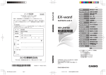
MICROWAVE OVEN
MODEL: EM044KIT-P00K (1000W 120V60Hz)
SERVICE MANUAL
CAUTION
BEFORE SERVICING THE UNIT,READTHE SAFETY PRECAUTIONS IN THIS
MANUAL
TABLE OF CONTENTS
(page)
INTRODUCTION AND SAFETY PRECAUTIONS--------------------------------------------- 1-1
INTRODUCTION ----------------------------------------------------------------------------------1-2
SAFETY PRECAUTIONS------------------------------ -------------------------------- ---------1-3
SCHEMATIC DIAGRAM ----------------------------------------------------------------------------2-1
HEATING PRINCIPLE OF MICROWAVE-------------------------------------------------------3-1
TROUBLESHOOTING PROCEDURES------------------------------------------------------------4-1
COMMON BREAKDOWN AND MEANS OF REPAIRING -----------------------------------5-1
CRITICAL PARTS SERVING-------------------------------------------------------------------------6-1
SAFETY CHECKS AND TESTS AFTER SERVING -------------------------------------------7-1
CONSTRUCTIONAL CHECKS-------- ---------------------------------------------------------7-1
INSULATION RESISTANCE TEST------------------------------------------------------------7-1
MICROWAVE LEAKAGE TEST----------- --------------- ---------------- --------------- -------7-2
EXPLODED VIEW---------------------------------------------------------------------------------------8-1
PRECAUTIONS TO AVOID
POSSIBLE EXPOSURE TO EXCESSIVE
MICROWAVE ENERGY
A. Do not attempt to operate this oven with the
door open since open-door operation can
result in harmful exposure to microwave
energy. It is important to defeat or tamper
with the safety interlocks.
B..Do not place any object between oven front
face and the door or allow soil or cleaner residue
to accumulate on sealing surfaces.
C. Do not operate the oven if it is damaged. It is
particularly important that the oven door close
properly and that there is no damage to the (1)
Door (bent), (2) hinges and latches (broken or)
loosened). (3) door seals and sealing surfaces.
D. The oven should not be adjusted or repaired by
anyone except properly qualified service
INTRODUCTION AND SAFETY PRECAUTIONS
When
using
electrical
appliances,
basic
safety
precautions should be followed, including the following:
replacement. Do not attempt to service or repair
this appliance.
WARNING-To reduce the risk of bums, electrical shock,
fire, injury to persons or exposure to excessive
microwave energy:
1. READ ALL THE INSTRUCTIONS BEFORE USING
THE APPLIANCE.
2. Read and follow the specific “Precautions to avoid
possible exposure to excessive microwave energy”
found above.
3. This appliance must be grounded and properly
polarized. Connect only to a properly grounded and
polarized outlet.
4. Install or locate this appliance only in accordance
with the installation instructions described in this
manual.
5. Some products such as whole eggs and sealed
containers, such as closed glass jars, may explode
and should not be heated in this oven.
6. Use this appliance only for its intended use as
described in the manual. Do not use corrosive
chemicals or vapors in this appliance. This type of
oven is specifically designed to heat, cook, dry, or
defrost food. It is not designed for industrial,
laboratory, or commercial use. It is intended for
home use only. Do not use for drying clothes, linens,
newspaper, or similar non-food type items.
7. Make sure that all persons using this appliance,
especially children, are closely supervised and
properly instructed on how to use this appliance.
8. Do not operate this appliance if it has a damaged
cord or plug, if it is not working properly, or if it has
been damaged or dropped.
9. This appliance should be service only by qualified
service personnel. Contact the nearest authorized
service facility for examination, repair or
10.Do not cover or block any openings on the
appliance. Do not store items on top of microwave
oven if there are louvers on top of oven.
11. Do not store this appliance outdoors. Do not use
this product near water-for example, near a kitchen
sink, in a wet basement, or near a swimming pool,
and the like.
12. Do not immerse cord or plug in water.
13. Keep cord away from heated surfaces.
14. Do not let cord hang over edge of table or counter.
15. When cleaning surfaces of door and oven that
come together on closing the door, use only mild,
nonabrasive soaps or detergents applied with a
sponge or soft cloth.
16. To reduce the risk of fire in the oven cavity:
a) Do not overcook food, especially starchy as
bacon. Carefully attend appliance if paper,
plastic, or other combustible materials are
placed inside the oven to facilitate cooking.
b) Remove wire twist-ties from paper or plastic
bag before placing bag in oven.
c) If materials inside the oven should ignite,
keep oven door closed, turn oven off, and
disconnect the power cord, or shut off power
at the fuse of circuit breaker panel.
d) Do not use the cavity for storage purposes.
Do not leave paper products, cooking
utensils, or food in the cavity when not in use.
e) Do not put metal inside the oven, except as
specifically described in the manual or
cookbook if supplied with this oven.
1-1
17. Liquids, such as water, coffee, are able to
overheated beyond the boiling point without
appearing to be boiling. Visible bubbling or boiling
when the container is removed from the microwave
oven is not always present. THIS COULD RESULT
IN VERY HOT LIQUIDS SUDDENLY BOILING
OVER WHEN A SPOON OR OTHER UTENSIL IS
INSERTED INTO THE LIQUID. To reduce the risk
of injury to persons:
i)
Do not overheat the liquid.
ii)
Stir the liquid both before and halfway
through heating it.
iii)
Do not use straight-sided containers
with narrow necks.
iv)
After heating, allow the container stand
in the microwave oven for a short time
before removing the container.
v)
Use extreme care when inserting a
18. VENTILATING HOODS
1)
Clean Ventilating Hoods FrequentlyGrease should not be allowed to
accumulate on hood or filter
2) . When flaming floods under the hood,
turn the fan on.
INTRODUCTION
This Microwave Oven service Manual is printed in a loose leaf format. Each part is divided into sections relating
to a general group of components and each section is subdivided in various parts describing a particular
component or service procedure.
The subdividing of the subject matter plus the loose leaf form will facilitate the updating of the manual as new or
revised components and service procedures are introduced.
Each page of this service manual will be identified in the lower right hand corner and as new or revised pages are
published it will be easy to keep the manual up to date by following the filing instructions on the cover letter.
This Service Manual is a valuable service tool and care should be taken to keep it up to date by prompt and
proper filling of subsequent pages as they are issued.
1-2
SAFETY PRECAUTIONS
PRECAUTIONS TO BE OBSERVED BEFORE AND DURING SERVICING TO
AVOID POSSIBLE EXPOSURE TO EXCESSIVE MICROWAVE ENERGY:
A. Do not operate or allow the oven to be operated with the door open.
B. Make the following safety checks on all ovens to be serviced before
activating the magnetron or other microwave source, and make repairs as
necessary.
(1) Interlock operation
(2) Proper door closing
(3) Seal and sealing surfaces (arcing, wear, and other damage).
(4) Damage to or loosening of hinges and latches.
(5) Evidence of dropping or abuse.
C. Before turning on microwave power for any service test or inspection
within the microwave generating compartments, check the magnetron,
wave guide or transmission line, and cavityfor proper alignment, integrity,
and connections.
D. Any defective or misadjusted components in the interlock, monitor, door
seal and microwave generation and transmission systems shall be
repaired, replaced, or adjusted by procedures described in this manual
before the oven is released to the owner.
E. The microwave leakage check to verify compliance with the Federal
performance standard should be performed on each oven prior to release
to the owner.
F. Operate the oven from a properly grounded AC outlet capable of supplying
THIS MANUAL, AS WELL AS THE INFORMATION CONTAINED IN IT, IS TO BE USED ONLY BY
AN AUTHORIZED SERVICE TECHNICIAN FAMILIAR WITH AND KNOWLEDGEABLE OF
PROPER SAFETY AND SERVICING PROCEDURES AND POSSESSING HIGH QUALITY TEST
EQUIPMENT ASSOCIATED WITH MICROWAVE AND ELECTRICAL APPLIANCE REPAIR.
ALL INDIVIDUALS WHO ATTEMPT REPAIRS BY IMPROPER MEANS OR ADJUSTMENT,
SUBJECT THEMSELVES AND OTHERS TO THE RISK OF SERIOUS OR FATAL INJURY.
1-3
SCHEMATIC DIAGRAM
Model
2-1
THE HEATING PRINCIPLE OF MICROWAVE
Microwave is one kind of radio wave whose wave length is very short, frequency is very high. Therefore, it is called ultrahigh
frequency electromagnetic wave. Microwave can heat food mainly result in the mutual affect of the food in the microwave field and
microwave field itself.
Under the affect of microwave field, the thermal effect mechanism produced from the mutual affect of the microwave and the food
includes two aspects: One is Dielectric loss of polar molecule, the other is conductive loss of ion.
Usually, food is constitute of organism (plant and animal).The organism is formed by all kinds of polar water molecule, polar protein
molecule, and all sorts of salt ion. The center of gravity of the positive and negative charge in the molecule is not coincide. In normal
condition, the molecule is in irregular order due to its thermal action, thus the food do not appear polarity (FIG.1-1a).Under the action
of outer electric field, the positive end of the polar molecule trend to the negative electric field, the negative end of polar molecule
trend to the positive electric field, and somewhat arrange in order through the direction of the electric field(FIG.1-1c).This
phenomenon usually be called “TORQUE POLARITY”. When the outer electric field apply for the opposite polarity, the polar
molecule then arrange an opposite direction order accordingly (FIG.1-1b).If the direction of the outer electric field changed
repeatedly, the polar molecule would repeatedly sway accordingly. During the swaying, it understands that the polar molecule would
produce heat due to somewhat similar friction among them.
When the electric field is applied for ultrahigh frequent microwave field from the outside, its direction would change tens billion times
per second, so do the molecule. This kind of molecule swaying producing similar frictional heat from the interference and block of
the action strength among the molecule, and changed to microscopic microwave heating. Microwave heating not only concerned the
nature of the matter itself, but also closely connected with the electric field strength and frequency. When the frequency is low, the
molecule swaying rate and the acute degree of the mutual friction among the molecule is low, and would produce much heat. When
the frequency is too high, as the swing of the polar molecule is with rotating inertia, it made the swing do not in line with the changing
rhythm of the electric field because of the friction drag, thus, actually lowed the polar molecule swaying speed. The friction dragging
degree is concerning about the magneto electric wave frequency, polar molecule shape, and the matter’s sticky degree. To different
matter’s molecule, there are different special frequency zone. Those aho absorb microwave energy from these zone are most
capable to turn microwave energy to heat energy.
Apart from the above said action, there is another action which is electric ion under the action of microwave field, act fiercely
accompanied with the acceleration of electric field. The positive ion transfer to the negative polarity of the field while the negative ion
do opposite. Accompanying with the changing electric field, the electric ion changing accordingly. During the transferring, heat
produced with the crash among the ion. This kind of action take the main effect to those microwave heating of high salt molecule.
No matter it is the polar molecule swaying or the ion transferring, they both are turning the microwave energy which the heating
matter got from the microwave field to hear energy. From the analysis of theory, we can draw such a conclusion that the power
which a unit of volume matter absorbed from the microwave field as the following formula:
Pa=KE fErtg
Pa Stands for the power the heated matter absorbed from the microwave field.
K Stands for a constant
E Stand for microwave field strength
F Stands for the microwave frequency.
g Stands for loss angle tangent of the heated matter
E Stands for relative dielectric constant of the heated matter.
3-1
TROUBLE SHOOTING PROCEDURES
Before overhauling a microwave oven, you should judge the breakdown and the cause correctly, then you can repair it with
corresponding ways. The overhauling must be proceed in order, any hasty conclusion is not recommendable, otherwise
overworking would be done when repair. The microwave oven may occur compound breakdown due to all kinds of different reasons,
thus, when overhaul, they all should be taken into consideration. Special attention must be given to the microwave leakage and the
electric insulation when examine because they may do harmful to the repairing staff.
.MEANS OF THE BREAKDOWN EXAMINING
How to examine a microwave oven with breakdown? A better means which demonstrated in practical operating are through
inspecting and listening. On the basis of large amounts of perceptual knowledge, you can judge and analysis the breakdown quickly
and correctly.
1. Inspection.
Inspect whether the oven shape is disordered and where is the disordered position, if any. It is normal if the cabinet disordered
a little, but abnormal if the oven, the door disordered, the door hook broken, the door crooked, or there are too much looseness
between the door and the oven after the door is closed.
2. Listening.
Listening to the voice of the oven operating and the noise of the fan after it conducted. Minor “wen wen” noise, cycling “kala”
noise and “shishi” noise should be consider as normal. But it is abnormal if the following noise occurred:
(1) Sound “wenwen” noise.
(2) Long time “shishi” noise.
(3) Strike voice like “pipa pipa”.
.SPOT EXAMINING STEPS OF THE MICROWAVE OVEN.
1. Examine the microwave insulating resistance.
Measure the insulating resistance with a multi meter or a mega ohmmeter the value should not less than 2 mega ohm.
Otherwise, part examination should be taken at once. Such as checking whether the motor, the thermal cutout, the transformer
or the capacitor are electricity leaking.
2. Examination of the resistance value of the microwave oven.
Close the door, set the time (the oven is at operating condition but the power plug haven’t been plugged in), measure the two
feet(L-N)of the power plug with Rx1 grade of a multimeter, the resistance value should be about 2.5 ohm.
If open circuit occurred, then you must check whether the 8A fuse is broken the primary winding of the transformer is open
circuit the thermal cutout is open circuit or not, you must check whether the interlock device is put through or all the plugs are
connected well. If short circuit occurred or the resistance less than 1.5 ohm, you should check whether the primary winding of
the power transformer is short-circuited or part short-circuited.
3. Examination of microwave leakage
Measure the microwave leakage with a microwave leakage Measure. Place a graduate of 275ml water at the middle of the
glass tray of the oven (FIG.5-1). Close the door, power set high, time set to 3 minutes, press the starting button to operate the
oven. After rectified the microwave leakage measure, measure around the door crack, those hole position of the window and
the air vent at four sides of the oven with the probe of the measure. When measure, the moving speed of the probe should not
exceed 25mm per second, and the measuring direction should be the same with the outing direction of the microwave leakage
(FIG.5-2).
When measuring, the ultimate value of microwave leakage of all the measured position should not exceed 1 milliwatt/cm, or
should be considered as abnormal.
4. Examine when the oven at operating, but the food can’t be heated.
(1) Examine when the lamp is on, the glass tray is cycling, the fan operating in normal;
Take off the cabinet, starting the oven, measure the plug of the transformer with a multi meter to see whether it is enough
to 120v.If it is enough to 120v,then the secondary high voltage of the transformer should be examined as FIG.5-3.
Probe of the Microwave measure
275ml
Glass tray
FIG.5-1
FIG.5-2
Damaged
4-1
(2) Measure it with the 2500V alternating grade of model 500 multi meter. One rod of the multi meter connect the iron core
of the transformer, the other rod connect the secondary high voltage plug(FIG.5-4).The multi meter reading should be about
2100v(when measure, be careful with the high voltage).If no voltage at all, it indicates that the transformer has broken, and
should be replaced by a new one. If it is enough to 2100v,then check the filament voltage of the transformer with alternating
10v grade of a multi meter, the value should be about 3.4v(FIG.5-5).
Transformer
Secondary winding
Primary winding
Fig.5-3
Fig.5-4
Filament winding
Fig.5-5
Fig.5-6
Fig.5-7
(3) If there is no voltage at all, it indicates the transformer has broken, and should be replaced by a new one. If it is enough to
3.4x,check the filament resistance of the magnetron, measure the filament plug with the Rx1 grade of a multi meter
(FIG.5-6).If it is open-circuited, it indicates the magnetron has broken, and should be replaced be a new one. It is normal if
the resistance value is very small. Then check whether the magnetron steel has broken, if broken, replace with a new
magnetron.
(4) If there is no problem with the magnetron, check the high voltage diode then. Measure the diode with Rx10k grade of a
multi meter, the “+” rod end of the multi meter connect the cathode of diode, the “-“ rod end of the multi meter connect the
anode of the diode(FIG.5-7).The multi meter reading should be about 150 thousand ohm. Then change the rod to different
electrode, the reading should be “
”.If the reading is very small, and near to short circuit, it indicates the high voltage diode
has been punctured, and should be replaced by a new one.
Secondary
winding
Fig.5-8
Fig.5-9
4-2
(5) If the high voltage diode is OK, then check the forwarding plug of the transformer to see whether it is enough to 120v.If it is
not enough, check the micro-switch of the time and power distributor. Connect the two rod of the multi meter to the 1.2
place of the timer with Rx1k grade. It is normal if the reading is “0” when at cut off condition. If the reading is “ ”,it indicates
the micro switch has broken, and the timer should be replaced by a new one. If all the above examination shows normal,
then check whether the terminal plug of the magnetron and the capacitor have loosed, if it is loosed, pinch it tightly with a
pliers.
5.
Examine the starting and the
Pull out the power plug, take off the cabinet, discharge the capacitor, measure the resistance value of the primary winding and
the secondary winding of the transformer with a multi meter (FIG.5-10 and FIG.5-9). The resistance value of the primary
winding should be about 2.2 ohm, the secondary winding should be about 130 ohm, otherwise, it indicates the transformer has
broken, and should be replaced by a new one.
Transformer
Capacitor
Fig.5-11
Primary winding
Fig.5-10
If the transformer is normal, then the high voltage capacitor should be checked. Pull out the connecting plug of the capacitor,
and measure it with Rx1 grade of a multi meter, the two rod of the multi meter connect the two polarity of the capacitor. When
they just connected, the reading of the multi meter should be zero, then enlarge to nine mega ohm slowly. Change the rod to
different polarity, the reading repeat from zero to nine mega ohm (FIG.5-11),it means the capacitor is normal. If the indicator of
the multi meter can’t point out from zero to nine mega ohm, it indicates the high voltage capacitor has broken, and should be
replaced by a new one.
If it is normal between the two pole of the capacitor, then the insulation between the capacitor pole and the cabinet should be
replaced by a same model, same capacity one.
If the resistance value of the capacitor’s two pole are “ ”,the capacitor is normal. Then check the earth of the magnetron’s two
filament to see whether they are short-circuited (FIG.5-13).If they are short-circuited and the filament strikes the shell of the
magnetron, it indicates the magnetron has broken, and should be replaced by a new, same model one.
If the magnetron is also normal, then test the pilot switch. Pull out the two plugs of the switch, Measure it with the Rx1 grade of a
multi meter, the two rod connect the plug of the switch, the resistance value should be “ ”(FIG,5-8).Then press down the pilot
switch with a screwdriver, if the reading of the multi meter pointed to zero, it indicates the pilot switch has broken, and should
replace it with a new, same model one.
.REPAIRING METHOD OF SEVERAL BREAKDOWN
1.
Repair when there occurred large amounts microwave leakage. There are many factors, which may cause microwave leaking.
Following mentioned may be the main cause of microwave leakage:
(1) The door deformed, the hinge loosed or damaged that caused the door can not close tightly.
(2) The door pressing cover or the embed piece damaged or come off.
(3) Obvious damage or uneven of the oven.
4-3
(4) There are filth between the door and the oven.
(5) The door and the oven are serious loosed after the door closed.
Magnetron
Fig.5-13
(6) The crack of the door shielding net cover.
Before repairing, check whether the above listed point are existed, if not, can you start the microwave oven. Place a
graduate of about 275ml water at the middle of the glass tray, close the door, time set at 3 minutes, power at high, makes
the oven operating in normal. Rectify the microwave leakage measure, measure the amount of the microwave leakage
around the oven with its probe. If there are places which the leakage exceed the standard requirement, then repair them
accordingly. If the leakage amount exceed I mill watt/cm at the left door crack, then pull out the power plug, take down the
cabinet, adjust the screws of the hinge (up and low) as figure5-14 to less the gap between the door and the oven. Then
measure again, the leakage amount should less than I mill watt/cm. Generally, it should be controlled below 0.75 mill
watt/cm with some allowance.
Fig.5-14
Fig.5-15
If the leakage occurred at the right door crack, adjust the screws that fix the interlock holder and the hook. If the leakage is
on the larger side at the right-above of the oven, then adjust the upper screw as FIG.5-15.Loosen out the screw, push the
door close to the oven to hook the door hook with the plastic parts, the tighten the screw again. If the leakage is larger at
the right-below, then adjust the lower screw as FIG.5-15.Loosen the screw, push the door close to the oven to hook the
door hook with the switch holder tightly, then tighten the screw again, and open and close the door repeatedly to check
whether the door can operate flexibly, whether the hook and the switch are in their normal position. If it is not in position,
4-4
then adjust the door hook and the switch holder the loose between the door and the oven, then measure the leakage with
microwave leakage measure again.
If the leakage still exceed standard requirement, then inspect whether the right oven is even or not, if not, smooth it. Then
adjust the door and the oven to eliminate their loose to the ultimate.
If there still exist microwave leakage, measure near the magnetron with the probe of the microwave leakage measure. If
the leakage is larger, the oven should be turned off and check whether the four screws which fix the magnetron have been
loosed, if loosed, twist them tightly with socket wrench. If the four screws are fixedly, then the magnetron should be take
down to check the copper filament weaved washer of the magnetron has been placed well or whether the wave guide
housing coupling has been oxidized or have lacquer on it. If do have, scrape the oxidized layer or the lacquer off, when fix
the magnetron, the copper filament weaved washer must be placed well, the screws must be twist tightly. Then turn on the
oven and measure again until it complies with the requirement. If the microwave leakage is larger at those hole position of
the window board, the oven should be turned off to inspect whether there are crack among them(FIG.5-17).If several holes
formed a crack, it would enlarge the microwave leakage. If that is the case, it indicates the door has broken, and should be
replaced with a new door.
2.
Means of repair when the oven can heat, but the turntable glass can’t move
Firstly, check whether the turntable holder is placed correctly. If it is correct, then pull out the power plug and take down the
turntable combination, measure the resistance value of the turntable motor with Rx1k grade of a multi meter If it is
open-circuited, it indicates the turntable motor has broken, and should be replaced by a new, same model one. If the resistance
value is between 15-22k,it indicates the turntable motor is normal, then check the connecting shaft weave. If the plastic that the
shaft insert in has broken, a new shaft weave should replace it.
3.
Repair when the oven can heat, but the lamp is not on.
Pull out the power plug, take down the cabinet and discharge the capacitor.
Pull out the two terminal plugs of the lamp, measure the two plugs of the lamp with the Rx100 grade of a multi meter. If it is
open-circuited, it indicates the lamp has broken, and should be replaced by a same model one.
Fig.5-16
4.
Fig.5-17
Means of repair when the oven stop working after several minutes operating
The phenomenon indicated the thermal cutout is playing its protective role, and you should check whether the fan is working in
normal. Turn off the oven, pull out the power plug, take down the cabinet, discharge the capacitor, then turn the fan with hand to
see whether it is moving flexibly. If not, it indicates that the oil bearing of the fan motor has run off the oil, and should take down
the fan combination to repair the motor. Loosen the two screws which fix the bearing out the shaft and the bearing, and rinse
them with kerosene (ATTENTION: The bearing can only be wiped with a silk which moistened with kerosene rather than be
washed in the kerosene because there are felt on it. If the felt are soaked with kerosene, then the engine oil can not be sucked
up.).After the bearing being cleaned, the felt should be refueled fully with engine oil(for when the oven is operating, the engine
oil empty into the oil bearing slowly).Fix the bearing cover with two screws, turn the fan around till it can move flexibly. Than
install them to the oven, and plug in the two terminal plugs.
If the fan can move flexibly, then the winding of the fan motor should be examined. Measure the winding with Rx100 grade of a
multi meter, if it is open-circuited, it indicates the winding of the fan motor has broken, and should be replaced by a new, same
model one.
4-5
COMMON BREAKDOWN AND MEANS OF REPAIRING
PHENOMENON
1.When starting the oven,
the lamp is not on, the
turntable tray can’t rotate
and the food can’t be
heated
CAUSE
REPAIRINGMEANS
1. Change a new fuse.
2. Change
a
new
transformer.
3. Change a new capacitor.
4. Change a new pilot
switch.
5. Change a new interlock
switch.
6. Adjust the connection or
replace it by a new one.
7. Change a new book.
The primary and secondary winding, the 1. Change
a
new
filament of the transformer are open-circuited.
transformer.
The magnetron filament is open-circuited, the 2. Change the magnetron.
magnetic steel of the magnetron broken or the 3. Change the time power
distributor
or
the
magnetron is air leaking.
micro-switch.
Time and power distributor broken..
The plugs of the magnetron of the capacitor 4. Fix them.
loosed.
1. Change a new lamp
The lamp broken.
The plug fall off.
2. Insert the plug again
1. fuse broken
2. The primary and secondary winding of the
transformer are short-circuited.
3. The earthing or the polarity of the capacitor is
punctured.
4. The pilot switch can’t cut off.
5. The interlock switch hasn’t closed.
6. The power plug and the socket are not in good
connection.
7. The door hook broken.
2.When starting the oven, 1.
the lamp is on, the
turntable rotating, the fan 2.
cycling but the food
haven’t be heated.
3.
4.
3.The food can be 1.
heated, but the lamp is 2.
not on.
4.The food can be heated 1. The turntable motor broken
but the turntable tray is 2. The plug fall off
3. Connecting shaft weave broken
not rotating.
5.The oven can heat
within 2-3 minutes, but
can not heat from the
fourth minutes.
1. Change the turntable
motor
2. Insert the plug securely
3. Change the weave
1. The winding of the fan motor in open-circuited. 1. Change the fan motor
2. The fan falls off
2. Change the fan
3. The plug of the fan motor falls off
3. Insert the plug
4. The turntable shaft is griped with the motor 4. Overhauling them
bearing.
5. Repairing it
5. The cooling vent blocked
The high voltage diode was punctured
Change a new diode
6.When starting the oven,
it can’t heat, and with
“wenwen” noise
7.The oven can heat,but The iron core of the transformer loosed
with sound “shishi” noise
8.Large
amount
of 1. The door deformed
2. The door metal net cracked
microwave leakage
3. The gap of the door crack is too large
4. The welding point of the oven fall off
5. The screws which fix the magnetron loosed
6. The wave guide connection oxidized
7. The magnetron copper filament washer is too
thin cause the wave guide opening not in good
earth.
9.The door can’t open
1. After long time using, the wear and the
rust-eaten enlarged the gap of the door shaft
and the shaft hole, thus cause the door
crooked.
2. The door hook broken
10.The door release Wore aged after long time operating
button fall off
11.Electricity leaking
The earthing insulation resistances of all the
motors or the transformer are less than 2 mega
ohm.
Change a new transformer
1.
2.
3.
4.
5.
6.
Mend the door
Change the door
Adjust the gap
Change the oven
Tighten the screws
Scrape the oxidized and
tighten the screws
7. Thick the copper filament
washer
1. Adjust the hinge to rectity
the position of the door.
2. Change the hook
Overhaul it or renew it
Test where is the leaking
place, then repair it or
change
those damaged
components.
5-1
CRITICAL PARTS SERVICING
1. IMPORTANT THINGS TO DO PRIOR TO CRITICAL PART SERVICING
The following instructions are CRITICAL to the owner’s safety. Be sure to follow all the instructions. Contact the
manufacturer of distributor if you have any question.
1.1 If the oven is operative prior to servicing a Microwave Leakage Test (Microwave Emission Check) should be
performed prior to servicing the oven. Refer to Section 7.3,Microwave Leakage Test, for the detailed check
procedures.
1.2
in the event that any microwave oven found to have microwave emission level in excess of 4 mW/cm2.The
following procedures should be followed:
a. Inform the distributor, importer, or manufacture the finding. Record it in the
logbooks well.
b. Repair the unit at no cost to the owner.
c. Investigate the oven and ascertain the cause of the excessive leakage.
d. Hold the oven in your facility and instruct the owner not to use the unit until the oven has been brought into
compliance.
1.3 In the event that the oven operates with the door open.The following procedures should be followed:
a. Tell the user not to operate the oven.
b. Hold the oven in your facility until it is investigated and repaired.
c. Contact the manufacturer and CDRH(FDA) immediately.
2. Interlock Assembly Replacement and Adjustment
2.1
If you suspect defective primary, secondary or monitor interlock switches, use your ohmmeter(digital or analog
type the check the electrical continuity.
2.2
Make sure the power cord is pulled out and the high-voltage capacitor is discharged before the electrical
continuity check.
2.3
Set the ohmmeter to “Low Resistance” range and connect both leads (alligator clips) to the switch terminals.
2.4
Open the door and notice the meter reading. The primary or secondary interlock switch should show an “infinite”
resistance when the door is open. Replace it when it is defective. The monitor interlock should show a “zero or
near zero” resistance when the door is open. When the door is closed, the readings will be opposite.
2.5 If the oven has been received inoperative due to the failure of the monitored safety(primary and/or secondary)
interlock(s),you should replace all of the monitored safety interlock switched and the monitor switch.
2.6
Refer to Chapter 4, Sections and for how to remove and assemble the interlock and monitor switches.
2.7
Always refer to Section 0.4 for adequate wiring diagram. Monitor interlock must always be installed. Repeat Step
6.2.4 to check electrical continuity.
2.8
Perform required checks and tests as described in Chapter 7 before releasing the oven to the owner.
6-1
3.
Door and Hinge Replacement and Adjustment
3.1
Pull the power cord from the outlet. Check the door for warped or damaged areas. Check the hinges for broken or
worn areas. Check other areas such as cracked from glass, broken door latched, worn/cracked viewing screen
and etc.
3.2
After determining the door assembly should be replaced, check the parts list for the correct part number. All oven
door components must be ordered directly from the manufacturer or its authorized distributor.
4.
3.3
Refer to Chapter 4, Sections . . . . and
for how to disassemble, assemble and adjust the door and/or hinge.
3.4
Perform required checks and tests as described in Chapter 7 before releasing the oven to the owner.
Magnetron Replacement
4.1
Refer to Chapter 4, Section
for removing and replacing the magnetron. Check for the presence of the wire
mesh gasket before installation.
4.2
Perform required checks and tests as described in Chapter 7 before releasing the oven to the owner. Conduct a
Microwave Leakage Test(Refer to Section 7.5)at the magnetron area prior to installing the top cover.
SAFETY CHECKS AND TESTS AFTER SERVING
Constructional Checks
If mechanical or electrical(electronic) parts have been replaced be sure to follow the following steps.
1.1
Check for correct wiring, adequate mechanical decrements of parts, and firm connectors.
1.2
Check for adequate grounding.
1.3
Check the following items before turning the oven ON.
1)
Proper door closing, seal/choke surfaces, and hinges.
2)
No cabinet damage.
3)
Proper interlock and monitor operations.(Refer to Steps 6.2.2. to 6.2.4.)
Insulation Resistance Test
If the low voltage power supply has been repaired, use a 500 V Mega ohmmeter to measure the resistance between the
primary(Line and Neutral)of the power plug and operator accessible metal parts. The resistance should be no less than 2 Mega
Ohms. Repair the oven again when necessary.
7 -1
Microwave Leakage Test
In the event that magnetron, door, or hinge has been replaced or readjusted, a microwave test as follows must be preferred:
3.1
Test instruments required:
Microwave Survey Meter, Holaday Model HI-1710 or equivalent
600 ml glass beaker
3.2
Precautions
Turn the power off (or unplug the oven) immediately if the oven fails this test.
3.3
Plug the oven power cord into the power receptacle.
3.4
Turn on the Microwave Leakage Meter and warm up for at least 10 minutes. Set the meter response(filter selection)at
“FAST”.
3.5
Fill the glass beaker with 275(+/- 15) ml of cold water and place the beaker in the center of the turntable glass plate.
3.6
Close the oven door. Set the timer at “5 minutes”. Set the Power Level at “HIGH” or “100%” and start the operation.
3.7
Hold (by the handle portion) the probe(cone spacer)perpendicular to the areas under test for RF emissions. Move the
probe at a speed of no faster than 1 inch per second. The areas under test are:
1)
The
of the door/cavity seal.
2)
The area of the door screen.
3)
The area of control panel.
4)
The area near line cord.
5)
All vent openings.
6)
All cabinet seams.
7)
Other suspect areas.
3.8
At several locations in the vicinity of each high leakage point, hold the probe stationary until a steady state value is
reached on the Survey Meter. Observe the maximum leakage at each location
3.9
Set the Meter Response to “SLOW”: remeasure the leakage at the point of maximum leakage located in Step 7.3.8 above,
record the value and location of the maximum leakage measurement with the meter response on “SLOW’.
3. 10
The maximum RF emission (leakage) should be 4.0 mW/cm2 or less. If not, investigate and repair the oven again until it
passes the test
7 -2
1
图样代号 X
A
2
3
4
5
5
C00
D09
6
6
7
S05
C26
D06
8
8
C02
9
9
D
E
F
G
H
J
K
L
M
D07
C05
7
S03
D01
D03
C01
10
D02
10
C55
S03
11
11
D08
D05
12
门钩
13
14
15
零部件名称
16
SCREW ST4*8PBHC
3
C18
S05
SCREW ST4*8PBHC
SCREW ST4*12PWB
2
HC 2
D
D
D
D
D
06
07
08
09
14
BARRIER SCREEN *O
PANEL DOOR
GASKET DOOR
DECO. D/PANEL
HANDLE
1
1
1
1
1
C
C
S03
26
55
SWITCH CIRCUIT
SHIELDER
1
1
1
1
1
PCB ASS'Y
BARRIER SCREEN *I
18
05
C
D
1
1
1
DECO. MEMBRANE
SPRING LATCH
DECO. C/PANEL
LATCH
05
03
02
02
C
D
C
D
刘石永/2010.8.30
Qty.
1
1
1
PANEL CONTROL
ASS'Y DOOR FRAME
C01
01
16
设计/日期
Model EM044KIT
批准/日期
Part Name
ASS'Y C/PANEL
C
15
图样名称 IT 外观爆炸图
No.
00
D
Qty.
1
产品型号
Part Name
ASS'Y DOOR
零部件名称
13
00
No.
12
D
14
S03
A
M
L
K
J
H
G
F
E
D
B
D14
4
B
3
C
2
C
D00
1
8 -1
A
B
C
D
E
F
G
H
I
J
K
L
M
N
O
P
M12
1
1
2
2
D00
W00
3
3
S04
T04
T03
4
T02
4
W05
S03
S04
C00
5
5
S04
S04
A01
F14
W12
M13
Z02
B00
6
E11
6
S04
S07
S09
F11
E13 E14
S09
S04
E10
S09
S09
M04
M03
7
E60
S04
W08
E03
M11
E14
S04
S12
S09
S03
T01
A00
Z03
E13
7
8
S04
S09
L01
S09
13
9
W06
W07
W09
L03
E02
E16
S04 Z24
S07
L04
E01
S04
S04
S01
B01
S05
A13
L02
S09
10
S04
S04
Z01
S04
11
S04
M07
W03
W16
E07
E06
S04
S08
S11
12
S04
W02
L05
S04
S04
S04
Material or spec
S04
F13
S04 Z06
S04
W01
1
1
Quantity
1
Spacer
part name
Case Out
Cover Wave Guide
S04
E05
S04
S 10
S04
S28 S01
E16
限位柱
波导盖
F04 E17
A01
Z06
零部件名称
外罩
No.
Z24
1
15
ASS'Y Kits
1
2
14
安装套件
Cover Lamp
13
Z05
Cover Cavity Lamp
1
灯罩
Holder H.V.C
1
Z03
Guide Air Magnetron
Z15
Guide Air Outlet
导风底板
BRKT Damper
Motor Vent
Cover Vent Motor
Protector Air *R
1
1
1
1
1
磁控管导风板
炉灯盖板
电容器夹
涡流风机
Damper
W05
W16
Z01
出风导风罩
右栅格
W09
导风板安装板
W12
W08
导风板
1
W06
W07
1
1
1
Motor Fan
1
W03
1
Fan
Grille Vent
1
Guide Fan
Tray
1
1
风扇电机
Ring Rotating ASS'Y
扇叶
通风栅格
转盘
Coupler
风扇支架
T04
W00
转环
W01
T03
驱动轴
W02
T02
Motor Tray
3
转盘电机
SCREW CT4*10WBHC
S13
T01
2
Ф345
ST4*8WBHC
螺钉∅ 4*10
螺钉∅ 4*12(齿)
螺钉∅ 4*8(齿)
Screw Ф3*8
Screw Ф4*8
Screw Ф4*10
Screw Ф4*12
Screw Ф4*8
3
3
33
2
4
CT3*8BBHC
ST4*8PBHC
ST4*10TBHC
ST4*12PwBHC
CT4*8TBHC
CT4*10HwBHC
S07
螺钉∅ 4*8
ST4*8TB
S05
螺钉∅ 3*8
7
S04
1
4
3
2
螺钉∅ 4*25
螺钉CT4*10WBHC
螺钉∅ 4*6(不锈)
SCREW Ф4*6
S12
螺钉∅ 4*10(齿) Screw
ASS'Y Mounting Nut
安装螺母组件
螺钉∅ 4*8(不锈钢)Screw Ф4*8
SCREW Ф4*25
S11
S09
S03
Filter Charcoal
1
1
Ф4*10
S08
S01
炭素滤网
Light Tape
S10
M13
灯贴
Board Latch
Lever Switch
Microswitch Interlock
Microswitch Monitor
1
2
1
M11
联锁杠杆
联锁开关
Air Duct
E03
E05
E06
E07
E10
E11
E13
E14
E16
E16
E17
E60
M07
M04
磁控管
磁控管温控器
腔体温控器
高压变压器
高压电容
滤波板
高压二极管
保险管
灯泡
灯座
电源线组件
高压变压器温控器
涡流风机温控器
启动电容
安装板组件
灯玻璃
灯玻璃支架
Bottom Plate
ASS'Y Controller
ASS'Y Door
Magnetron
Thermostat MGT
Thermostat Cavity
H.V.Transformer
H.V.Capacitor
H.V.Diode
Filter Noise
Fuse
Lamp
Socket Lamp
Power Cord ASS'Y
Thermostat H.V.T
Thermostat Vent Motor
Capacitor Starting
Plate Mounting
Glass Lamp
BRKT Lamp Glass
Filter Oil
Guide Air
1
1
1
1
1
1
1
1
1
3
3
1
1
1
1
1
1
1
2
1
1
M03
底板
ASS'Y Base Plate
Base Plate
1
1
1
1
15
16
16
美 的 微 波 炉 制 造 有 限 公 司
EM044K**-P00A
The exploded drawing for
Quantity
1
BRKT Thermostat
14
part name
ASS'Y Cavity
日 期
Material or spec
Harness Main
L03
联锁支架
线束
监控开关
L02
主导风板
E02
门组件
L04
L01
L05
F14
E01
变压器安装板
控制组件
F11
D00
1
F13
侧导风板
油脂滤网
C00
B00
B01
底板组件
温控器支架
1
F04
A13
零部件名称
腔体组件
No.
A00
标记
审 核
13
A
B
C
D
E
F
G
H
P
O
N
M
L
8 -2