1
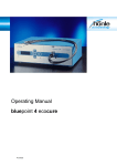
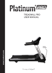
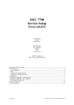
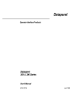
Service Manual Tunturi T70 /T80
1
T70 Console
T80 Console
2
Power board T70 /T80
Operating Mode
LED’s
Sleep Mode, Treadmill horizontal
Bright: 18V, AC1, READY, VCON
Increasing: MTR VOL
Bright or Off: SPD
Normal Mode
Bright: 18V, AC1, MTR VOL, READY, RELAY, VCON
Flashing: M_PWM, PWM, SPD
Failure Mode
LED’s
Over current condition
(Belt will have force for 5s max)
Bright: 18V, AC1, I LIM, MTR VOL, READY, RELAY, VCON
Flashing: M_PWM, PWM
Bright or Off: SPD
Shorted Motor
Bright: 18V, AC1, MTR SHRT, MTR VOL, READY, VCON
Flashing: PWM
Bright or Off: SPD
3
Designator Name
D33
18V
The function of each LED is as follows:
Description
Turns on when the transformer secondary that is attached to power
ground outputs power. This indicates that the low voltage transformer is
working and implies that the “hot side” control electronics are active.
D4
AC1
AC power is at the primary to the transformer.
D7
DOWN
Current is flowing in the elevation control circuit to allow for the down
relay controlling the elevation motor to activate.
D32
I LIM
Turns on when the current flowing through the motor reaches the circuit
set maximum. This indicates that the system is loaded to or beyond its
capacity.
D40
M_PWM Turns on when the power FET is conducting. The LED will seem to
become brighter as the PWM at the power FET approaches 100%
because it is flashing at a greater rate than the human eye can see.
D29
MTR
SHRT
D24
MTR VOL Turns on dimly when power is first applied and becomes brighter as the
large capacitor charges. When the LED is bright this indicates that the
motor controller is ready to power the motor.
D12
PWM
Turns on when the incoming PWM signal is logical high with a duty
cycle of less than 99%. The LED will seem to become brighter as the
incoming PWM approaches 99% because it is flashing at a greater rate
than the human eye can see.
D21
RELAY
Turns on when the console commands the relay to turn on. This
indicates that power is present at the relays to energize them. It implies
that the motor controller and the console are communicating.
D30
SPD
Flashes each time the speed sensor is triggered. This indicates that the
speed sensor is working and communicating with the motor controller.
This also indicates that the signal has been converted to a TTL output.
This does not indicate that the console is receiving the speed feedback.
D10
UP
Current is flowing in the elevation control circuit to allow for the up
relay controlling the elevation motor to activate.
D34
VCON
Turns on when the voltage regulator on the transformer secondary
attached to Chassis Ground that supplies the console outputs power.
This indicates that the low voltage transformer is working and implies
that there is enough power to turn the console on and that the “cold” side
electronics is active.
Turns on when excessive current passes through the FET. This LED
implies that there is a short in the motor or motor wiring.
4
5
Stop Code
E1
Reason
SPEED
STALL
Speed signal is
missing on the
console board
Solution(s)
The speed cable connection on the motor
controller's (power board) J6 is loose (the SPD
LED beside J6 should be on and flashing when
you move the belt with feet).
The optical speed sensor does not work. Swap
with a good sensor to see what happens.
The cable connecting the power board and the
console is loose or broken (please use a scope
to check the console and the power board’s pin
9 to see if there is a speed signal presenting
there or simply first use a good cable to swap it
and see if the problem is resolved or not.
The measured
speed is over the
maximum speed in
a certain amount.
E2
OVER
SPEED
E3
The measured
SPEED
speed is over the
RUNAWAY target speed in a
certain amount.
E16
STUCK
KEY
E18
EEPROM
FAIL
Not
assigned.
"OFF" is
displayed on
the
Elevation
window.
A key is holding
constantly for a
certain time
EEPROM selfcheck fails.
The elevation
malfunctions. The
console only
disables the lift
motor related
movements so that
the user can still
running on the belt.
The cable connecting the power board and the
console is broken. (Please check if the cable's
wire on pin 6 is exposed to a high voltage wire
easily; or simply first use a good cable to swap
it and see if the problem is resolved or not.)
The cable connecting the power board and the
console is broken. (Please check if the cable's
wire on pin 6 is exposed to a high voltage wire
easily; or simply first use a good cable to swap
it and see if the problem is resolved or not.)
A key button is loose or stuck.
Cycle power. If the code comes up again,
replace the board.
The elevation cable connection on the motor
controller's (power board) J4 is loose, or the
elevation cable connection on the motor
controller's (power board) J7 is loose; or the
wires to J7's pins 1 and 3 are swapped.
The cable connecting the power board and the
console is broken. (Please check if the cable's
wires on pins 2, 3, 10, 11 and 12 are in proper
condition; or simply first use a good cable to
swap it and see if the problem is resolved or
not.)
6
Service menu
Make sure the treadmill is in the start-up mode
( you might need to switch the machine off and on to reach this mode )
Enter the service menu by pushing following key sequence:
<SET>
<SET>
<SET>
<ENTER-JOGWHEEL>
<ENTER-JOGWHEEL>
( confirmed by an acoustic beep from monitor speaker )
( confirmed by an acoustic beep from monitor speaker )
( confirmed by an acoustic beep from monitor speaker)
( confirmed by showing message: Service menu )
( confirmed by entering the service menu )
The service menu consist of fifteen states.
You can navigate through the service menu by using the enterjogwheel. You can leave the service menu by pressing the Start/stop
button at any state ( except at state 9 : keyboard test )
When rotating enter-jogwheel clockwise:
1st
state : Minimum PWM
The distance screen will show the stored minimum PWM related to the
latest ran speed calibration procedure ( see state 12 : speed calibrate )
Press set if this value needs to be adjusted and use the speed-up /
-down button to adjust this value. Confirm the adjustment by pressing
the enter-jogwheel.
2nd
state : Half max. PWM
The distance screen will show the stored half maximum PWM related to
the latest ran speed calibration procedure ( see state 12: Speed
calibrate ) Press set if this value needs to be adjusted and use the
speed-up / -down button to adjust this value. Confirm the adjustment
by pressing the enter-jogwheel.
3rd
state : Maximum PWM
The distance screen will show the stored maximum PWM related to the
latest ran speed calibration procedure ( see state 12: Speed calibrate )
Press set if this value needs to be adjusted and use the speed-up / down button to adjust this value. Confirm the adjustment by pressing
the enter-jogwheel.
4th
state : Elevation minimum
The distance screen will read out the actual potential meter value of
the elevation unit. The elevation screen will show the target elevation
incline. This should be 0%
5th
state : Elevation maximum
The distance screen will read out the actual potential meter value of
the elevation unit. The elevation screen will show the target elevation
incline. This should be 12 %
6th
state : Magnet count ( software version ≤ V. 1.00 )
The distance screen will show the count of magnets. This count is used
by the speed sensor to measure the speed during speed calibration
and normal use. The number of magnets must me equal to the count
of magnets installed in front roller pulley. This number must be one
unless modified otherwise. To change the value press set and use
speed-up/ -down button to adjust value. Confirm the adjustment by
pressing the enter-jogwheel.
6th state : ( software version ≥ V. 0.09 )
X
X
x
7th
state : 10 rev. distance
The distance screen will show a value. This is the belt’s moving distance
in mm when turning the front roller 10 revolutions.
By adjusting the value slightly, you can precisely match the speed
calculated by the console with the actual speed measured by a
speed meter at the Motor Test screen. The value can be adjusted by
pressing the set button, and adjust with the speed-up / -down button
8th
state : Display test
Press enter-jogwheel to enter this option. If selected you will see all
digits light up in a random following order. You can leave this option by
pressing the enter-jogwheel.
9th
state : Keyboard test
Press enter-jogwheel to enter this option. By pressing a console button
you will see the readout of the button function in display screen.
Mention, you will leave this option if you press the enter-jogwheel again
10th state : HR test
Press the enter-jogwheel to enter this option. Monitor will test if an
external heart rate measurement signal is received. If not it will show in
distance screen:
If there is a signal received by the monitor it will be shown in Kcal an
elevation screen. It will also monitor the strenght of the signal.
Lowest signal is shown as 14.00 up to strongest signal 47.00
Normal user position should have a signal strengt between 35.00 and
40.00
It also will show if the messured hartrate signal is send by telemetry
chest strap or by contact HR ( only on T70 )
11th state : Motor test
Press the enter-jogwheel to enter this option.
Test elevation motor :
You can test the elevation unit by pressing the elevation-up/ -down
button. Treadmill will lower or upper it’s runningdeck like demanded.
• Kcal screen will show the measured potential meter readout
value of the lift motor unit.
• Elevation screen will readout the related inclination.
Test drive motor :
You can test the drive motor by pressing the speed-up/ -down button.
• time display will show measured speed in miles per hour.
• distance screen will show the PWM of the motor.
• speed screen will show the measured speed in kilometer per
hour.
Walking belt should start up at 40 PWM if not standing on it. If it starts at
a lower PWM it shows the belt runst extremly smooth.
state : speed calibrate
12th
Press enter-jogwheel to start speed calibration.
Display will show, start auto calibration press start. If you press the
start/stop button. The speed calibration will run automatically in
following order.
1
2
3
4
time.
Min. PWM
: Kcal screen will show PWM
Half max PWM : Kcal screen will show PWM
Max. PWM
: Kcal screen will show PWM
DC test
: the motor will be tested at full power for a short
During the speed calibration procedure
• time screen will show the measured speed in miles per hour
• distance screen will show the target speed
• show the measured speed in km per hour
5 cal passed
: This message will be shown if the speed
calibration procedure is successfully passed.
Press enter-jogwheel once to return to service menu.
state : elv. Calibrate
13th
Press enter-jogwheel to start calibration procedure. During calibibration
the Text screen will show: seeking maximum / minimum elevation
Treadmill will first go to maximum and will lower to minimum afterwards.
• Kcal screen will show potential meter value
• Elevation screen will show inclination of treadmill
• Distance will show maximum potential meter value
• Speed will show minimum potential meter value
After reaching the minimum inclination the treadmill will automaticly
run to the 0% setting.
14th
state : err. message : The distance screen will show wether the
error message function is selected in on or off mode. You can change
this valeu by pressing the speed down or speed up button. Press enterjogwheel to confirm and store the change.
• Off mode : Treadmill display will show error numbers ( example
Error 1 )
• On mode : Treadmill display will show error text message
( example speed stall )
15th
state : error list : press enter-jogwheel to see the logfile stored in
monitor eprom.
• Kcal screen will show Err 1 up to 5 ( make selection by pressing
incline up or down.
• Time screen will show error text message
• Distance screen will show error code number
It is unable to clear the logfile.
NB! Always when servicing the treadmill be sure that the power has
been switch off and the main cable is plugged off the from wall outlet.
Big capacitors on the control board might retain high voltage level
even for several hours after the unit has been plugged off from the
power outlet.
Error texts
Error Code
Error code
in *Off
setting
E1
Error code in
*ON setting
SPEED
STALL
Solution(s)
*See 14th state of
service menu
Speed signal is
missing on the
console board
The speed cable connection on the
motor controller's (power board) J6 is
loose (the SPD LED beside J6 should
be on and flashing when you move
the belt with feet).
The optical speed sensor does not
work. Swap with a good sensor to see
what happens.
The cable connecting the power board
and the console is loose or broken
(please use a scope to check the
console and the power board’s pin 9
to see if there is a speed signal
presenting there or simply first use a
good cable to swap it and see if the
problem is resolved or not.
E2
E3
OVER
SPEED
SPEED
RUNAWAY
The cable connecting the power board
and the console is broken. (Please
check if the cable's wire on pin 6 is
The measured speed exposed to a high voltage wire easily;
is over the maximum or simply first use a good cable to
speed in a certain
swap it and see if the problem is
amount.
resolved or not.)
The measured speed
is over the target
speed in a certain
amount.
The cable connecting the power board
and the console is broken. (Please
check if the cable's wire on pin 6 is
exposed to a high voltage wire easily;
or simply first use a good cable to
swap it and see if the problem is
resolved or not.)
Error Code
Solution(s)
Error code
in *Off
setting
Error code in
*ON setting
E16
A key is holding
constantly for a
STUCK KEY certain time
A key button is loose or stuck.
E18
EEPROM
FAIL
EEPROM self-check
fails.
Cycle power. If the code comes up
again, replace the board.
"OFF" is
displayed on
the Elevation
window.
The elevation
malfunctions. The
console only
disables the lift
motor related
movements so that
the user can still
running on the belt.
The elevation cable connection on the
motor controller's (power board) J4 is
loose, or the elevation cable
connection on the motor controller's
(power board) J7 is loose; or the wires
to J7's pins 1 and 3 are swapped.
Not
assigned.
*See 14th state of
service menu
The cable connecting the power board
and the console is broken. (Please
check if the cable's wires on pins 2, 3,
10, 11 and 12 are in proper condition;
or simply first use a good cable to
swap it and see if the problem is
resolved or not.)