1
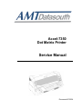
Accel-7350
Dot Matrix Printer
Service Manual
Document #130034
1
This Manual is to help qualified service engineers repair or adjust your AMT ACCEL7350 Printer.
Please read the manual carefully before repairing and adjusting your AMT ACCEL-7350
Printer.
The warranty will not cover any trouble with or damage to the printer resulting from
repair or modification by unqualified persons.
WARNING: Be sure to turn off the printer and disconnect the power
cord from the AC outlet before removing the top
enclosure. Failure to disconnect the power could result
in an electric shock
1. No part of this manual may be reproduced in any form.
2. This manual is subject to change without notice.
3. This manual was prepared with the greatest care. If you should find any unclear
points, mistakes, or omissions, please contact us.
4. We will not bear any responsibility for unsatisfactory results from the use this printer
despite item 3 above.
* EPSON is a registered trademark of S.Epson Corporation.
* LQ-2550 is a registered trademark of S.Epson Corporation.
* IBM is a registered trademark of International Business Machines Corporation.
* IBM 2391 is a registered trademark of International Business Machines
Corporation.
• Windows is a registered trademark of Microsoft Corporation.
1
TABLE OF CONTENTS
Printer Specifications
4
Parallel Interface Specifications
11
Serial Interface Specifications
13
Print Head Adjust Label
16
Printer Features
17
Hexadecimal Dump Function
18
Self Test Function
18
Safety Auto Stop Function
19
Print Head Gap Adjustment
19
Print Position Adjustment
20
Paper Feed Position Adjustment
22
Wiring Diagram
23
Control Diagram
24
Troubleshooting
25
Control ROM and PCB Replacement
25
Troubleshooting Guide
26
Error Message Remedies
27
Trouble Symptoms
31
Repair Flow Charts
33
Mechanical Replacement
49
Print Head and FFC Cable Replacement
51
Ribbon Guide Assembly Replacement
52
Carriage Motor Assembly Replacement
53
Carriage Timing Belt Replacement
54
Line Feed Motor Assembly Replacement
55
Platen Replacement
56
Friction Mechanism Replacement
56
Ribbon Motor Assembly Replacement
58
HA Motor Replacement
59
Paper Edge Sensor Replacement
60
Carriage Replacement
61
2
TABLE OF CONTENTS
Replacement of Sensors
63
Parallelism Adjustment
67
Lubrication
68
Electronic Repairs
70
HA Motor Driver Circuitry
78
Ribbon Motor Driver Circuitry
79
MC Motor Driver Circuitry
80
LF/HC Motor Driver Circuitry
81
Print Pin Driver Circuitry
85
Detecting Circuitry
87
Power Supply PCB
90
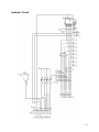
Indicator Circuit
93
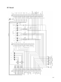
I/F Circuit
94
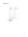
Slide SW Circuit
95
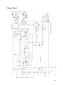
Power Circuit
96
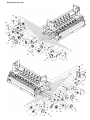
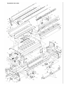
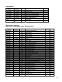
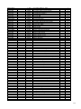
Exploded Drawings and Part Numbers
97
3
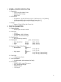
1. GENERAL PRINTER SPECIFICATION
1.1. Description
o 24 pin Serial Dot Matrix Printer
o Flat bed, Wide Carriage
o Beige Color
1.2. Dimensions:
o At Operation - (W) 25” [635 mm] x (D) 18.3” [465 mm] x (H) 11.6” [294mm]
o At Storage (without paper tractor and paper support) –
(W) 25” [635 mm] x (D) 13.2” [335 mm] x (H) 11.6” [294mm]
1.3. Weight:
o Approx. 52 lbs (23.5 kg) with Tractor Unit
2. PRINTING PARAMETERS
2.1. Printing Method
o Serial impact dot matrix method
2.2. Print Head
o 24 pins
o Pin Diameter: .010” (0.25 mm)
o Head life: 300 million stroke/pin
2.3. Print Direction
o Bi-directional logic seeking
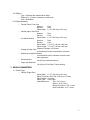
2.4. Print Speed
(pitch, dot structures)
o High Speed Draft
400 cps
(10 cpi, 24 x 9)
o Draft
300 cps
(10 cpi, 24 x 12)
o LQ
150 cps
(10 cpi, 24 x 36)
2.5. Number Of Copy & Print Speed
o Normal Mode
Original + 5
Draft
10 cpi, 300 cps
LQ
10 cpi, 150 cps
o High Impact
Original + 7
Draft
10 cpi, 200 cps (1 pass printing)
LQ
10 cpi, 100 cps (1 pass printing)
2.6. Print Width
o 136 columns (10 cpi)
2.7. Line Feed Speed
o 6 inch/seconds (with continuous line feed)
2.8. Throughput
o ISO/IEC 10561, Letter-Performance
o High Speed draft 340 pph
o DRAFT 290 pph
o LQ 200 pph
4
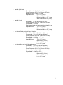
2.9. Ribbon
o Type - Cassette with endless fabric ribbon
o Ribbon Life -15 million characters in draft mode
o Color - Real Black
2.10. Paper Handling
o Fanfold Paper, Front Push
Insertion:
Front
Ejection:
Rear
Paper Width: 8 ~15” (203.2 mm–381 mm)
o Fanfold paper, Rear Push
Insertion:
Rear
Ejection:
Front
Paper Width: 8 ~15” (203.2 mm–381 mm)
o Cut Sheet, Manual
Insertion:
Rear
Ejection:
Front
Paper Width: 7.2~16.5” (182 mm–420 mm)
Paper Length: 7.2~16.5” (182 mm–420 mm)
Capacity of Hopper: 100 sheets
o Change of Paper Path:
Lever/electrical control, and software command
o Adjustment of paper thickness:
Lever/electrical control, software command, and
Auto adjustment
o Skew detection:
Yes (Only for Manual Insertion)
o Paper Jam Detection:
Yes (Only for Front/Rear Tractor feeding)
3. MEDIA PARAMETERS
3.1. Media Type
o Fanfold (Single-Part)
Paper Width: 8 ~15” (203.2 mm–381 mm)
Paper Thickness: .003~.005” (0.08 mm–0.12 mm)
Paper Weight: 16~24 lbs
Paper Type: Plain Paper
Unprintable Area:
Top: .012” (3 mm)
Bottom: .012” (3 mm)
Before Perforation: .012” (3 mm)
After Perforation: .012” (3 mm)
5
o
Fanfold (Multi-parts)
Paper Width: 8 ~15” (203.2 mm–381 mm)
Paper Thickness: .005~.02” (0.12 mm–0.52 mm)
Number of Copies: Original + 7 max
Unprintable Area:
Top: .012” (3 mm)
Bottom: .012” (3 mm)
Before Perforation: .012” (3 mm)
After Perforation: .012” (3 mm)
o
o
o
Fanfold (Label)
Paper Width: 8 ~15” (203.2 mm–381 mm)
Paper Thickness: .003~.007” (0.08 mm–0.18 mm)
Paper Weight: 16~36 lbs
Step between label and base sheet: Less than 0.12 mm
Unprintable Area:
Top: .012” (3 mm)
Bottom: .012” (3 mm)
Before Perforation: .012” (3 mm)
After Perforation: .012” (3 mm)
Cut Sheet (Single-part) with Manual Insertion
Paper Width: 7.2~16.9” (182 mm–430 mm)
Paper Length: 7.2~16.9” (182 mm–430 mm)
Paper Thickness: .003~.005” (0.08 mm–0.12 mm)
Paper Weight: 16~24 lbs
Paper Type: Plain Paper, Fine PPC
Unprintable Area:
Top: .012” (3 mm)
Bottom: .012” (3 mm)
Right: .012” (3 mm)
Left: .012” (3 mm)
Cut Sheet (Multi-part) with Manual Insertion
Paper Width: 7.2~16.9” (182 mm–430 mm)
Paper Length: 7.2~16.9” (182 mm–430 mm)
Paper Thickness: .005~.02” (0.12 mm–0.52 mm)
Number of Copies: Original + 7 max
Paper Weight: 16 lbs x (1+ 7P)
Unprintable Area:
Top: .012” (3 mm)
Bottom: .012” (3 mm)
Right: .012” (3 mm)
Left: .012” (3 mm)
6
o
o
Card with Manual Insertion
Paper Width: 7.2~16.9” (182 mm–430 mm)
Paper Length: 7.2~16.9” (182 mm–430 mm)
Paper Thickness: .003~.079” (0.08 mm–2.0 mm)
Paper Weight: 16~47 lbs
Paper Type: Plain Paper
Unprintable Area:
Top: .012” (3 mm)
Bottom: .012” (3 mm)
Right: .012” (3 mm)
Left: .012” (3 mm)
Cut Sheet (Single-part) with ASF
Paper Width: 7.2~16.9” (182 mm–430 mm)
Paper Length: 7.2~16.9” (182 mm–430 mm)
Paper Thickness: .003~.004” (0.08 mm–.11 mm)
Paper Weight: 16~20 lbs
Paper Type: Plain Paper, Fine PPC
Unprintable Area:
Top: .012” (3 mm)
Bottom: .012” (3 mm)
Right: .012” (3 mm)
Left: .012” (3 mm)
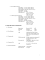
4. PRINT EMULATION & CHARACTER
4.1. Emulations
Epson Mode
IBM Mode
OKI
Epson LQ-2550
IBM 2391
OKI DATA 8480
ADP
OEM1
OEM2
ANK
High-Speed Draft, Draft, Roman,
Sans Serif, Courier, Prestige, Script,
Gothic, OCR-A, OCR-B, Orator and
Orator-S
EPSON mode ANK
EPSON character set, code page 437,
850, 860, 863, 865, 857, 858,
ISO-8859-1
code page 437, 850, 860, 863, 865,
857, 858, ISO-8859-1
4.2. Font Typeface
4.3. Character Set
IBM mode ANK
4.4. Character Pitch
ANK
10, 12, 15, 17.1, 20 and 24 cpi
Proportional
EPSON mode ANK
IBM mode ANK
128 characters
32 k bytes
4.5. Download Character
7
4.6. Barcode Symbology
Industrial 2 of 5Interleaved 2 of 5
Matrix 2 of 5
Codabar
Code 11
Code 39
Code 93
Code 128
EAN-8
EAN-13
UPC-A
UPC-E
Postnet
Element (created in elements)
4.7. Graphics Resolutions
360 x 180 dpi (HXV), Horizontal adjacent dots cannot be
printed
4.8. Printer Drivers
Windows 95/98/Me, NT 4.0, 2000/XP, Vista
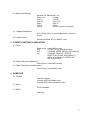
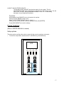
5. CONTROL SWITCHES & INDICATORS
5.1. Power
Power switch
LCD
LED
Key
located left front side
122 (W) x 32 (H) dots bitmap display
4 (ONLINE, SPEED, ERROR, HIGH IMPACT)
8 (ONLINE, TEAR OFF, SPEED &
RESET, EJECT/LOAD, HIGH IMPACT &
MENU, LF & MICRO LF, ENTER & ALT,
RLF & MICRO RLF)
5.2. Paper Path Lever Adjustment
Control Panel located left front side
5.3. Paper Thickness Lever Adjustment
Control Panel located left front side
6. INTERFACE
6.1. Parallel
Centronics Parallel
(Reverse: IEEE-1284 nibble mode)
(Forward: IEEE-1284 compatibility mode)
6.2. Serial
EIA-232 Standard
6.3. Buffer
64 K bytes
8
7. DETECTION & PROTECTION FUNCTION
7.1. Type
Paper Detection
Paper Jam Detection
Paper Skew Error Detection
Head Overheat Protection
Cover Open Detection
8. ACOUSTIC NOISE
8.1. Specification
Less than 58 dB(A) (LQ printing, fanfold, ISO 7779)
9. RELIABILITY & SAFETY
9.1. Print Head Life
300 million stroke / pin
9.2. Total Print Volume
12 million lines
9.3. Safety Standards
Equivalent to the following Standards
U.S.A. version UL60950, CSA 22.2 No.60950
Europe version: CE marking EN60950
9.4. EMI
Equivalent to the following Standards
U.S.A. version FCC class B
Europe version:CE marking
EN55022 class B
EN61000-3-2
EN61000-3-3
9.5. Immunity
Equivalent to the following Standards
EN55024 (CE marking)
9.6. MTBF
10000 hours
9.7. MTTR
30 minutes
9
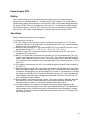
10. POWER
10.1. Power Supply
AC 220V -10%, AC 240V +10%, Frequency 50 Hz/60Hz
AC 100V -10%, AC 120V +10%, Frequency 50 Hz/60Hz
10.2. Power Consumption
LQ Self Printing: 140W
Draft Self Printing: 170W
Stand-by: 40W
Energy Star mode: 15W
11. OTHER
11.1. Temperature
At Operation
At Storage
41~104o Fahrenheit (5~40o Celsius)
-22~149o Fahrenheit (-30~65o Celsius)
At Operation
At Storage
20% RH–80% RH (No condensing)
10% RH–90% RH (No condensing)
At Operation
At Storage
(W) 25”(635 mm) x (D)18.3”(465 mm) x (H) 11.6” (294mm)
At Operation
Approx. 52 lbs (23.5 kg) with Tractor Unit
11.2. Humidity
11.3. Dimensions
(W) 25”(635 mm) x (D)13.2”(335 mm) x (H) 11.6” (294mm)
11.4. Weight
10
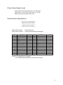
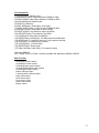
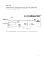
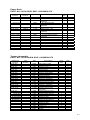
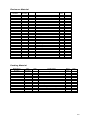
Parallel Interface Specifications
Cable Side Connector
Printer Side Connector
Cable type
PIN
1
2
3
4
5
6
7
8
9
10
11
12
13
14
15
16
17
18
Notes:
SIGNAL
STROBE*
DATA 1
DATA 2
DATA 3
DATA 4
DATA 5
DATA 6
DATA 7
DATA 8
ACK*
BUSY
PE
SELECT
AUTOFEED *
HIGH
LOW
CHASSIS GND
HIGH
DDK 36-pin 57-30360-D8 or equivalent
ELCO 36-pin 00834-6360020858 or equivalent
Twisted paired cable with ground line and maximum of 10 feet.
IN/OUT
IN
IN
IN
IN
IN
IN
IN
IN
IN
OUT
OUT
OUT
OUT
IN
OUT
OUT
OUT
PIN
19
20
21
22
23
24
25
26
27
28
29
30
31
32
33
34
35
36
SIGNAL
GND
GND
GND
GND
GND
GND
GND
GND
GND
GND
GND
HIGH
INITIAL*
ERROR*
HIGH
NC
HIGH
SELECT IN *
IN / OUT
OUT
IN
OUT
OUT
OUT
IN
(1) * is a negative logic.
(2) HIGH is pulled up to +5V by 2.2k ohms.
(3) NC stands for no connection.
(4) CHASSIS GND and GND are connected in the printer.
(5) LOW is pulled down to GND by 2.2k ohms.
11
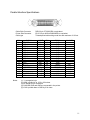
Printer Input Signals
DATA1-DATA8
8bit data signals with DATA 1 being the Least Significant Bit (LSB), and DATA 8
being the Most Significant (MSB).
STROBE*
A strobe signal for reading 8-bit data. When this signal goes "low", data is read.
The data is latched on the falling edge of STROBE*.
The next STROBE* pulse shall not occur until the trailing edge of the BUSY
signal from the previous data.
INITIAL*
A signal for initializing the printer (similar to turning power on). The signal goes
"low" to reset the printer, then when the signal returns "high" the printer will
initialize.
AUTO FEED*
This signal is ignored.
SELECT IN*
This signal is ignored.
Printer Output Signals
BUSY
A signal indicating that printer is busy. When this signal goes "high", the printer
does not accept data from the host. The printer causes the BUSY signal to go
"high" in the following cases.
(1) When the initializing operation is being executed;
(2) When data is input with the STROBE* signal;
(3) When the self test print is executed;
(4) When the printer is in the offline state;
(5) When the printer cover is opened;
(6) When a paper out condition or other error takes place.
ACK*
A signal, which is output in synchronization with the transition of BUSY from
"high" to "low". ACK* indicates the printer is ready to accept the next data byte.
In the cases (4), (5), and (6) above, the ACK* signal is not output.
PE
When paper is not loaded, this signal goes "high". When paper is loaded, this
signal goes "low".
ERROR*
This signal goes "low" in the following cases;
(1) when the paper out or the paper error takes place;
(2) when one of the function errors takes place;
(3) when the printer cover is opened; or
(4) when the printer is in the offline state
However, this signal stays "high" in the IBM mode when the offline state is
entered from the control panel.
SELECT
This signal is always HIGH.
12
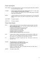
Printer Output Signal Levels
All the signals used in the printer are in the TTL levels.
"HIGH" level: +2.4 to 5.0 [V], "LOW" level: 0 to 0.4[V]
Measured at input terminals of the printer.
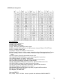
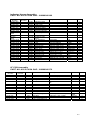
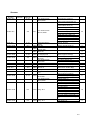
Serial Interface Specifications
Cable Side Connector
Printer Side Connector
PIN
1
2
3
4
5
6
7
8
9
10
11
12
13
SIGNAL
CHASSIS GND
TXD
RXD
RTS
CTS
NC
SIGNAL GND
NC
NC
NC
NC
NC
NC
25-pin (male type)
25-pin (D-sub connector (female type)
IN/OUT
OUT
IN
OUT
IN
PIN
14
15
16
17
18
19
20
21
22
23
24
25
SIGNAL
NC
NC
NC
NC
NC
NC
DTR
NC
NC
NC
NC
NC
IN / OUT
OUT
Notes:(1) NC stands for no connection.
(2) CHASSIS GND and GND are connected in the printer.
13
Printer Input Signals
RXD
Receive Data
A serial data line that consists of a start bit, data bits, (party bit), and stop bit. The
configuration of the data length (7 or 8 bits), parity and stop bit are set in the
setup mode from the control panel. RXD signal level is determined as "0" when
"high" and as "1" when "low".
CTS
Clear To Send
This signal is ignored.
Printer Output Signals
TXD
Transmit Data
A Serial output data line that sends XON, XOFF, ACK, and ID sequence. This signal
is sent regardless of whether CTS and DSR is "high" or "low". The format of the
data is the same as the received data.
TXD signal level is determined as "0" when "high" and as "1" when "low".
RTS
Request To Send
Always held in the ON ("space" or "high") state.
DTR
Data Terminal Ready
This signal represents the busy state of the printer. When signal is "low", it indicates
that the printer is busy and therefore data cannot be sent to the printer.
When this signal is "high", it indicates that the printer is ready and thereby data can
be sent to the printer. In the case of the XON/XOFF protocol, this signal is always
"high".
+3 through +15V
Signal Signals "HIGH" (ON, SPACE = Logic "0"):
"LOW" (OFF, MARK = Logic "1") :
-3 through -15V
Handshake Protocol
DTR (READY/BUSY) Protocol
A protocol that indicates the printer state with the signal line DTR (terminal
No.20). When the printer is in the ready state, the signal line is high (+12V).
When the printer is in the busy state or in the offline state, the signal line is low
(-12V). When the printer is in the busy state and in the offline state, the host
must not send data to the printer. However, the printer will accept data from the
host when busy is indicated until the buffer is filled.
Power ON state After the power is turned on and the initialization of the printer
is completed, DTR is set "high".
14
XON/XOFF Protocol
A protocol whereby the printer sends to the host XON (11h) and XOFF (13h)
codes to indicate the printer the printer's state.
The XOFF (13h) code is sent to the host to indicate not ready. In either the
busy or offline state, CTS is held "low".
When the power is turned on, the XON code is sent to the host.
In the following cases, the XOFF code is sent to the host.
(1) When the printer state changes from ready to busy.
(2) When the printer state changes from ready to offline.
(3) When printer receives 64 bytes to data after condition (1) or (2) occurs.
(However, when the remaining capacity of the buffer is smaller than 64
bytes, the XOFF is not sent to the host).
(4) When the buffer is full regardless of the online state or the offline state.
In the following cases, the XON code is sent to the host.
(1) When the printer state changes from busy to ready.
(2) When the printer state changes from offline to online.
(3) After the power is turned on, when the printer enters the online state.
Baud Rate
In the setup mode, one of the following baud rates can be selected: 300, 600,
1200, 2400, 4800, 9600, and 19200.
Serial Data Structure: data frame consists of, start bit (1) + data bits (7 or 8) +
parity bit (0 or 1) + stop bit (1 or 2).
15
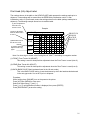
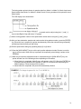
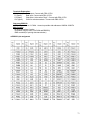
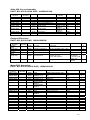
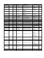
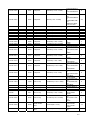
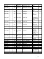
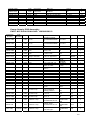
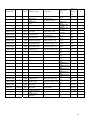
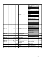
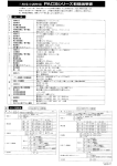
Print Head (HA) Adjust Label
The numbers shown in the table on the HEAD ADJUST label represent the settings made prior to
shipment. These settings will be erased from the EEPROM by initialization routine 3. After
initialization routine 3 is performed, restore the settings shown on the label (settings made prior to
shipment). The following example shows how to read the table.
(1) Auto 0 adjustment
when the Front
Tractor is used
(2) Auto 0 adjustment
when the Rear Tractor
is used
(3) Backward travel in
the HA auto mode
(4) Printing pressure
adjustment for copy
paper
Example
HA ADJUST
100
FRONT
10
1
100
REAR
10
1
10
BACK
1
10
MULT
-1
0
0
0
0
0
0
0
0
0
0
1
1
1
1
1
1
1
1
1
1
2
2
2
2
2
2
2
2
2
2
3
3
3
3
3
3
3
3
3
3
4
4
4
4
4
4
4
4
4
4
5
5
5
5
5
5
5
5
5
5
6
6
6
6
6
6
6
6
6
6
7
7
7
7
7
7
7
7
7
7
8
8
8
8
8
8
8
8
8
8
9
9
9
9
9
9
9
9
9
9
FRONT:120
REAR:90
BACK:50
FRONT:-2
Note: If a minus sign is shown in the first-digit line of “MULT,” the setting is a negative number.
(1) FRONT (Front Tractor HA ADJUST)
This setting is used for head position adjustment when the Front Tractor is used (Auto 0).
(2) REAR (Rear Tractor HA ADJUST)
This setting is used for head position adjustment when the Rear Tractor is used (Auto 0).
(3) BACK (BACK PULSE: Basic backward travel in the HA auto mode)
This is the BACK PULSE setting. It sets the distance by which the head travels backward
in the auto gap mode. It is set to 50 prior to shipment.
Procedure:
While holding down [ONLINE], turn on the power to the printer.
Press [ALT] then [MENU] to enter menu
Select HA Adjust using [←] and [→].
Press [↓] or [↑] until the desired number is displayed, then press [ENTER].
Press [HIGH IMPACT] to save the setting.
16
(4) MULT (HA MULTIPART ADJUST)
The HA MULTIPART ADJUST sets the print density for copy paper. The HA
MULTIPART ADJUST setting adjustment is enabled only in the HA auto mode. The HA
MULTIPART ADJUST setting is adjustable between -5 and +10. As the setting
decreases, the print darkness increases.
Procedure:
While holding down [ONLINE], turn on the power to the printer.
Press [ALT] then [MENU] to enter menu
Select HA MULTIPART ADJUST using [←] and [→].
Press [↓] or [↑] until the desired number is displayed, then press [ENTER].
Press [HIGH IMPACT] to save the settings.
Printer Features
(Refer to USER'S MANUAL for details)
Setup options
The setup options configure the printer to work with the current operating environment.
•
To enter the setup mode, depress the ALT and MENU keys simultaneously.
LCD
17
Hexadecimal Dump Function
The hexadecimal dump function produces an exact printout of the codes received by the printer.
To enter the hexadecimal dump mode, depress the SPEED key while turning on the printer's
power. Continue pressing key until the display reads “Hex Dump”.
Draft mode Hexadecimal Dump: Power ON + SPEED key
LQ mode Hexadecimal Dump: Power ON + SPEED key + ONLINE key
When the host sends output to the printer, all codes and data are printed in hexadecimal format.
The example below shows a BASIC program list and the resulting printout.
Program list:
10 LPRINT "STANDARD"; CHR$(10);
20 LPRINT CHR$(27);"E";
30 LPRINT "EMPHASIZED"; CHR$(10);
40 LPRINT CHR$(27);"F";
Printed sample:
(Standard printout)
STANDARD
EMPHASIZED
Hexadecimal Dump mode:
•
•
By comparing the characters printed in the right column with the hex codes, you can verify
exactly what codes are being sent to the printer. If the code sent is a printable character
(20h-7Eh), that character is printed in the right column. If the code sent is a non-printable
character, such as a control code, a dot is printed.
To exit from the hexadecimal dump mode, turn off the power switch or press the ALT then
RESET keys.
Self-Test Function
The self-test prints a continuous pattern of characters, either in draft or LQ. The font is determined
by the setup setting.
•
Select paper path and load paper.
•
To initiate the draft self test, depress the LF key while either turning on the power. Continue
pressing the LF key until the print test begins.
•
To initiate the LQ self test, depress both the LF and ONLINE keys while either turning on the
power.
•
To terminate or stop the self test function, either turn off the power or press the ONLINE key.
18
Safety Auto Stop Functions
•
Cover Open Sensor
When the front cover is open:
The printer stops printing (C motor is disabled, but front operation keys -LF, RLF, MICRO
LF, MICRO RLF - are operable).
"FRONT COVER OPEN" is displayed on LCD.
The ONLINE lamp blinks.
•
Overheat Sensor (in the print head)
When high temperature is detected in the print head, the printer automatically takes the
following actions:
Temperature > 115°C (Voltage at the test point TP 11 > 3.98 V)
Stop printing, and then moves the carrier in full printing width.
Temperature > 110°C (Voltage at the test point TP 11 > 3.85 V)
Reverse logic seek.
Head Gap Adjustment
This printer has a mechanism to automatically adjust the head gap after measuring the paper
thickness. As there is variance from printer to printer, the head gap of each printer is adjusted to the
optimum setting at the factory prior to shipment.
Operating Procedure
(1) Select the rear tractor paper path and feed a 15-inch wide sheet of paper.
(2) While simultaneously holding down the [LF] and [RLF] keys, turn on the printer. The printer will
enter the head gap adjustment mode.
(3) The LCD will have the display shown below. Select Front or Rear using the [←] key (SPEED) or
the [→] key (TEAR OFF).
The front head gap adjustment setting is used for front tractor feed and manual feed.
The rear head gap adjustment setting is used for rear tractor feed and cut-sheet feed
(CSF).
(4) Press the [↑] key (LF) to display the numeric gap setting. Press the [↓] key (RLF) to select the
current setting. NOTE: the current setting is indicated with an asterisk (*).
HA GAP
ADJ FRONT
HA GAP
ADJ REAR
(5) Press the [↓] key (RLF), and the printer will print out the gap adjustment pattern.
The figures to the left of the gap adjustment pattern represent the [gap settings].
The figures on the right represent the [number of pulses from home (top)].
After the printing is complete, the LCD displays the current gap adjustment setting, as
shown below.
160*
19
(6) Based on the gap adjustment pattern printout, select the gap adjustment settings that will provide
the optimum print density. Designate the selected gap adjustment setting on the LCD using the
[↓] and [↑] keys. Press the [ENTER] key and the printer will adjust the head gap using the
selected settings and print out the confirmation pattern.
(7) After you have adjusted the front and rear head gaps, press the [HIGH IMPACT] key.
The front and rear [gap adjustment settings] and the [number of pulses from home] will
be stored in the EEPROM, and the printer will initialize itself automatically.
Print Position Adjustment
This printer has two print position adjustment modes, “print start position adjustment mode (Mode
A)” and “bidirectional print position adjustment mode (Mode B),” in order to minimize the effects of
variance between individual printers and age-related deterioration. These modes enable fine
adjustment of the print position in accordance with its carrier speed.
The print start position adjustment mode (hereinafter referred to as Mode A) is used to align the print
start positions of the print modes with different print speeds. This mode sets the print start position
constant for any print speed.
The bi-directional print position adjustment mode (hereinafter referred to as Mode B) aligns the
characters in lines printed at the same speed in different directions. This mode sets the optimum
value for each speed.
A change in Mode A affects Mode B. If the Mode A setting has been edited, the Mode B setting will
also require adjustment. The printer, therefore, automatically moves to Mode B after it enters and
exits Mode A. When the Mode A setting has not been edited, you can adjust the print position in
Mode B only.
Operating Procedure
(1) Select the rear tractor paper path and feed a 15-inch wide sheet of paper.
(2) While simultaneously holding down the [ENTER] and [RLF] keys, turn on the power. The printer
will enter the print position adjustment mode.
(3) This screen will change to the Mode A menu in one second.
(4) Select Mode A or B using the [←] and [→] keys. The following steps are common in Modes A
and B.
(5) Press the [ENTER] key to start printing the timing pattern of Mode A (or B). The currently
selected timing number is marked with the “*” character.
20
The timing pattern printout shows six speed modes from Mode 1 to Mode 6 in Mode A and seven
Speed modes from Mode 0 to Mode 6 in Mode B, and 13 timing numbers will be printed for each
Speed mode.
The LCD display is as shown below.
(6) While referring to the pattern printout, select the speed mode to adjust using the [←] and [→]
keys to best align the top and bottom “H” pattern.
(7) Select a timing pattern number in the speed mode number above using the [↑] and [↓] keys.
(8) After you have selected a speed mode number and a timing pattern number, press the [ENTER]
key. When this key is pressed, the printer simultaneously stores the selected timing temporarily
and starts printing according to that timing.
(9) Edit the speed mode settings by repeating steps (6) to (8) above.
(10) Press the [HIGH IMPACT] key to exit the print position adjustment mode. Be sure to use this
key to exit the mode. When this key is pressed, the temporarily stored timing is written to the
EEPROM.
(11) When the print position adjustment mode is completed using the [HIGH IMPACT] key, the
printer will take one of the following actions depending on the modes.
a. When Mode A is completed, Mode B menu will appear on the LCD. When the [ENTER] key
is pressed after the Mode B menu appears on the LCD, the printer will start printing the
Mode B pattern. Follow the steps from (6) above.
b. When Mode B is completed, the printer will automatically initialize.
21
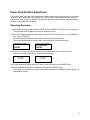
Paper Feed Position Adjustment
This printer detects the edge of the loaded paper with the edge sensor (reflection type) on the ribbon
guide of the print head and feeds the paper to the TOF position. If the feed position of a printer is
judged to be out of position by more than the specified distance, due to variance between individual
printers, it is adjusted before shipment.
Operating Procedure
(1) While simultaneously holding down the [TEAR OFF] and [EJECT/LOAD] keys, turn on the power.
The printer will enter the paper feed position adjustment mode.
(2) The LCD will have the display shown below. Select Front or Rear using the [←] key (SPEED) or
the [→] key (TEAR OFF).
The front adjustment setting is used for front tractor feed and manual feed.
The rear adjustment setting is used for rear tractor feed and cut-sheet feed (ASF).
TOF ADJUST
FRONT
TOF ADJUST
FRONT
(3) Press the [↑] key (LF), and the printer will enter the adjustment setting selection mode.
The current setting will appear on the LCD as shown below.
0/120*
0/120*
(4) Edit the adjustment setting using the [↑] and [↓] keys and then press the [ENTER] key.
(5) After the adjustment has been completed, press the [HIGH IMPACT] key.
The front and rear paper feed position settings will be stored in the EEPROM, and the printer will
automatically initialize.
22
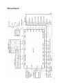
Wiring Diagram
23
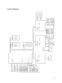
Control Diagram
24
Troubleshooting
Control ROM and PCB Replacement
When an EEPROM error or sensor problem arises, if there is no mechanical problem and if the
control ROM on the PCB is not the latest version, then replace the control ROM with the latest
version.
After you have replaced the control ROM, perform EEPROM initialization routines 1 and 2. After the
initialization routines, conduct a self-test to check print quality. If the problem is not solved by the
replacement of the control ROM, replace the control PCB and perform EEPROM initialization
routine 3.
Initialization of EEPROM
(1) Initialization Routine 1
Initializes the entire panel data settings stored in the EEPROM. To start the routine,
simultaneously hold down the [HIGH IMPACT] and [LF] keys and turn on the power.
(2) Initialization Routine 2
Learns the following sensor information and stores it in the EEPROM:
• Thresholds of the right/left edge sensors
• Threshold of the manual feed paper sensor
• Reference pulse for skew detection
When performing this routine, be sure to remove paper from the printing station and place 15
inch paper on the rear tractor (do not feed it in). To start the routine, simultaneously hold down
the [SPEED] and [TEAR OFF] keys and turn on the power.
(3) Initialization Routine 3
Initializes all of the data in the EEPROM. Routine 3 = Routine 1 + Routine 2 + Clearing of print
position adjustment data, head gap adjustment data, and paper feed position adjustment data.
When performing this routine, be sure to remove paper from the printing station and place 15
inch paper on the rear tractor (but do not feed it in). To start the routine, simultaneously hold
down the [ONLINE] and [EJECT/LOAD] keys and turn on the power. After you have performed
initialization routine 3, be sure to adjust the print position, the head gap, and the paper feed
position.
25
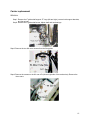
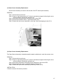
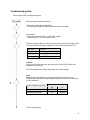
Troubleshooting Guide
Appearance Checks
Localize defective parts such as broken switches and levers, damaged FFC cable, loose
connections, burned components or blown fuses.
Functional checks
Define the defective functional block without disassembling the printer:
• Power-on initialization check (Checking printer power)
• Display indicator check (lamps operate abnormally)
• Checking on the error messages
• Performing self test check
• Sending printable characters from the host system to check the output (Head
Adjustment Lever)
• Checking function after Program ROM replacement
• Line feed control function check (Reverse line feeding stops after exceeding 22
inches)
Voltage check on the test points specified on Main PCB:
(Remove the top cover and lift the mechanism. Then inspect from the rear side.)
• +5V(Vcc)
No.32 pin of U8 (OPTION FONT) of the Main PCB.
• +40V
The left side lead wire of the resistor R209 of the Main PCB.
Note: When the interlock SW is OFF, the output of this point is open.
When the interlock SW is ON, the output of this point is 40V.
Components checks
• You can perform component level repairs using voltage/ampere meters,
Oscilloscope.
• You may be required to understand the electric component characteristics and the
operation principles, before you make any repairs. For the power supply PCB, many
details are provided for your troubleshooting aids.
26
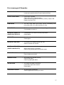
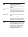
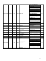
Error messages & Remedies
HEAD PROTECTION
•
Print head is overheated. The printer automatically resumes to its
normal print operation when the print head cools down.
FRONT COVER OPEN
•
Front Cover is opened.
Check if the cover is closed properly.
Check the cover open sensor connector (CN25) on Main PCB.
Replace the Main PCB.
RAM ERROR
•
The error lamp blinks and buzzer sounds immediately after
turning the power on or after the printer is reset.
PARK ERROR
•
Fanfold paper is not fed back to the packing position properly.
Cut the paper to remove it.
PAPER OUT FRONT TR
(PAPER OUT REAR TR)
•
Fanfold paper is not set on the front (rear) tractor.
Reload paper.
SET PAPER
•
A cut sheet is not loaded into the printer.
Reload paper.
PAPER OUT ASF (CSF)
•
A cut sheet is not loaded into the ASF unit.
Install cut sheets into the ASF.
PAPER JAM FRONT TR
(PAPER JAM REAR TR)
•
A paper jam occurs at the front (rear) tractor.
Adjust tractor tension if necessary.
Remove the jammed paper and reload a paper.
SET PAPER AGAIN
•
Fanfold paper is not fed properly.
Remove paper and reload.
REMOVE PAPER
•
A cut sheet is not ejected properly.
Remove the paper.
Check for paper path debris.
SKEW ERROR
•
A cut sheet is loaded on the skew.
If necessary adjust roller tension.
Reload paper.
JAM SENSOR ERROR
•
The jam sensor is defective.
Remove paper dust from the jam sensor.
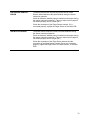
27
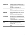
HAI SENSOR ERROR
•
The Head Adjust (hereinafter HA) Sensor detects an error when the
head is moved to the home position for HA.
Check to determine whether anything is obstructing the operation of
the HA Motor.
Check the connection of the HA Sensor harness. If it is connected
properly, replace the HA Sensor or the Main PCB.
HA SENSOR ERROR
•
The printer fails to detect the paper thickness during head
adjustment.
Check the connection of the HA Encoder harness. If it is connected
properly, replace the HA Encoder PCB or the Main PCB.
HOME SENSOR
ERROR
•
The printer fails to detect the print-head position. (Carriage Error)
Check to determine whether anything is obstructing the operation of
the HC Motor.
Check the connection of the Home Sensor harness. If it is
connected properly, replace the Home Sensor or the Main PCB.
FUNCTION MCMTR1
ERROR
•
The MC Sensor (Front Friction) detects an error when the printer is
initialized or when the front friction is adjusted.
Check to determine whether anything is obstructing the operation of
the Front Friction Motor.
Check the connection of the MC Sensor (Front Friction) harness. If
it is connected properly, replace the MC Sensor (Front Friction) or
the Main PCB.
FUNCTION MCMTR2
ERROR
•
The MC Sensor (Rear Tractor) detects an error when the printer is
initialized or when the paper feed path is changed.
Check to determine whether anything is obstructing the operation of
the Rear Tractor Motor.
Check the connection of the MC Sensor (Rear Tractor) harness. If it
is connected properly, replace the MC Sensor (Rear Tractor) or the
Main PCB.
28
FUNCTION MCMTR3
ERROR
•
The MC Sensor (Front Tractor) detects an error when the printer is
initialized or when the paper feed path is changed.
Check to determine whether anything is obstructing the operation of
the Front Tractor Motor.
Check the connection of the MC Sensor (Front Tractor) harness. If
it is connected properly, replace the MC Sensor (Front Tractor) or
the Main PCB.
FUNCTION MCMTR4
ERROR
•
The MC Sensor (Rear Friction) detects an error when the printer is
initialized or when the rear friction is adjusted.
Check to determine whether anything is obstructing the operation of
the Rear Friction Motor.
Check the connection of the MC Sensor (Rear Friction) harness. If
it is connected properly, replace the MC Sensor (Rear Friction) or
the Main PCB.
RIGHT EDGE SENSOR
ERROR
• The difference between the maximum and minimum Skew Sensor
values falls below the specified level during the sensor instruction
operation.
Check to determine whether paper is loaded into the printer during
the sensor instruction operation. (This error also occurs if paper is
not loaded properly due to a paper jam.)
Check to ensure that the Skew Sensor is mounted properly, the
Skew Sensor harness is connected properly, and the FFC harness
between the Main PCB and the Head Connecting PCB is
connected properly. If they are mounted or connected properly,
replace the Skew Sensor or the Main PCB.
LEFT EDGE SENSOR
ERROR
• The difference between the maximum and minimum Edge Sensor
values falls below the specified level during the sensor instruction
operation.
Check to determine whether paper is loaded into the printer during
the sensor instruction operation. (This error also occurs if paper is
not loaded properly due to a paper jam.)
Check to ensure that the Edge Sensor is mounted properly, the
Edge Sensor harness is connected properly, and the FFC harness
between the Main PCB and the Head Connecting PCB is
connected properly. If they are mounted or connected properly,
replace the Edge Sensor or the Main PCB.
29
PAPER EDGE SENSOR
ERROR
•
The difference between the maximum and minimum Paper
Sensor values falls below the specified level during the sensor
instruction operation.
Check to determine whether paper is loaded into the printer during
the sensor instruction operation. (This error also occurs if paper is
not loaded properly due to a paper jam.)
Check the connection of the Paper Sensor harness. If it is
connected properly, replace the Paper Sensor or the Main PCB.
SKEW PULSE ERROR
•
The printer fails to acquire the criteria for skew detection during
the sensor instruction operation.
Check to determine whether paper is loaded into the printer during
the sensor instruction operation. (This error also occurs if paper is
not loaded properly due to a paper jam.)
Check the connection of the Edge Sensor harness and the
connection of the Skew Sensor harness. If they are connected
properly, replace the Edge Sensor, the Skew Sensor, or the Main
PCB.
30
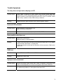
Trouble Symptoms
The lamp does not light and no display on LCD
Possible cause:
Power cable is defective or loose. Power lines from the power switch are
disconnected. Loose connection between the main PCB and indicator PCB.
Loose connection on the Main PCB and power PCB. Fuse (F1) is blown. Power
PCB circuitry is defective. Main PCB circuitry is defective.
Remedy:
Replace defective parts and refer to the "Electric Repairs" section.
Incorrect LCD indication
Possible cause:
Loose connector on the indicator PCB.
Main PCB circuitry is defective.
Remedy:
Reinstall the connector properly or replace the Main PCB.
Home position detection error
Possible cause:
Head carrier malfunctions.
Defective sensor or interlock switch.
Remedy:
• Check if the head carrier smoothly moves across its carrier bar. If not, replace
the print head, head carrier, or carriage bar.
• Check the interlock switch and the connection of the connectors, CN28 on the
Main PCB.
RAM error
Possible cause:
Internal RAM error in CPU or external RAM error.
Remedy:
Replace the control PCB.
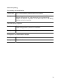
Improper carrier movement
Possible cause:
Remedy:
Carrier runs along a bent carrier bar.C motor is defective. Timing belt is too
loose. Print head position is too close to the platen. Main PCB is defective.
Readjust the head position, repair/replace defective components, check motor
for mechanical problems, or check pulses from Main PCB.
31
Abnormal printing
Dot is missing in horizontal direction.
Possible cause:
A pin in the printhead is defective. Main PCB is defective.
Remedy:
Replace the print head if a print pin is bent or broken and if 14 Ω of resistance
between GND and each pin is not measured on the print head terminal.
Replace the defective components on the Main PCB, such as the driving
transistor or fuse for missing pin.
Vertical dot spacing is improper.
Possible cause:
Print head is defective.
Paper holding pressure by tractor R/L is insufficient.
Remedy:
Replace the print head or the tractor spring.
Dot alignment in horizontal direction is improper.
Possible cause:
C motor is defective.
Remedy:
Replace the C motor.
32
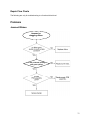
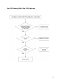
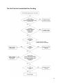
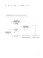
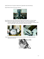
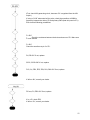
Repair Flow Charts
The following are only for troubleshooting to a functional block level.
Problems
Jammed Ribbon
Jammed or
dragging ribbon
Is the printhead printing
with good quality?
33
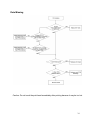
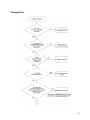
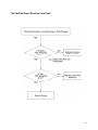
Dots Missing
Caution: Do not touch the print head immediately after printing because it may be too hot.
34
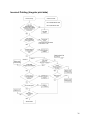
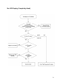
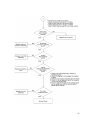
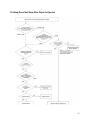
Extra Dot Printing (Improper character)
35
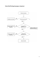
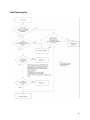
Incorrect Printing (Irregular print data)
36
No LCD Display (Half of the LCD lights up)
37
No LCD Display (Completely blank)
38
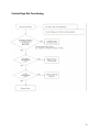
Control Keys Not Functioning
39
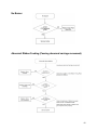
No Buzzer
Abnormal Ribbon Feeding (Causing abnormal carriage movement)
40
No Line Feed or Inconsistent Line Feeding
41
Carriage Error
42
43
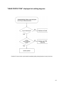
"HEAD PROTECTION" displayed but nothing happens
Caution: Do not touch the print head immediately after printing because it may be too hot.
44
Cover Open Error Will Not Cancel With Cover Closed
45
No Fanfold Paper Reverse Line Feed
46
Printing Does Not Stop After Paper Is Ejected
47
Not Powering Up
48
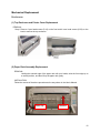
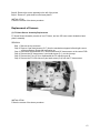
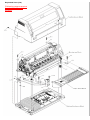
Mechanical Replacement
Enclosures
(1) Top Enclosure and Printer Cover Replacement
REMOVAL
Step 1. Remove 3 pan head screws (S-16) on the front and 4 truss head screws (S-22) on the
back to remove the top enclosure.
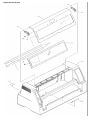
(2) Paper Rack Assembly Replacement
REMOVAL
Holding the external edge of the paper rack with your hands, raise the front edge up to
a vertical position, and then lift up the paper rack gently.
INSTALLATION
Follow the reverse of the above procedure as the way shown in the User's Manual.
Raise Up
Remove
49
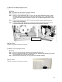
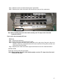
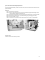
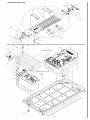
(3) Mechanical Block Replacement
REMOVAL
Step 1.The paper rack and cover L/R must be removed.
Step 2. The top enclosure must be removed.
Step 3. Remove 1-pan head screws (M4 x 32.6) on the right front mechanism holder B, rotate
the metal plate to the right. Remove 1-pan head screw (M4 x 32.6), 1-pan head screw
(S-18) on the left mechanism holder B. Remove the mechanism holders and the switch
holder.
Step 4. Remove 2 pan head screws (S-17) from the mechanism stoppers (left and right rear
corners of the mechanism).
Step 5. Lift up the back of the mechanism, and disconnect all the harnesses from the printed
circuit board assembly. Remove the mechanism from the bottom enclosure.
Right Side View
INSTALLATION
Follow the reverse of the above procedure.
(4) Bottom enclosure Replacement
REMOVAL
Step 1. The top enclosure and the mechanism must already be removed.
Step 2. Remove 2 flat head screws (S-21) on the power jack. Remove GND screws (S-14) (Note:
do not separate the screw from its GND wire.)
Step 3. Disconnect all the harnesses from the printed circuit board assembly.
INSTALLATION
Follow the reverse of the above procedure.
50
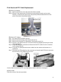
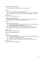
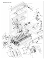
Print Head and FFC Cable Replacement
REMOVAL (Print Head)
Step 1. Open the printer front cover and remove the ribbon cassette.
Step 2. Remove 2 pan head screws (S-6) that are securing the print head onto the carrier.
Remove 1 screw from the carrier cover and pull the printhead toward the front of the
printer. Disconnect the printhead cables.
REMOVAL (FFC Cables)
Step 1. Print Head must be already removed.
Step 2. Remove the carrier motor, 4 pan head screws (S-16).
Step 3. Remove the rear guide FFC upper plate, 3 pan head screws (S-6).
Step 4. Remove 2 pan head screws (S-17) from the mechanism stoppers (left and right corners
of the mechanism).
Step 5. Lift up the back of the mechanism and disconnect the FFC cables from the connectors
on the control PCB unit.
Step 6. Lift up the FFC guide plate and remove cables from the retainers with tweezers or a
screwdriver.
Step 7. Disconnect the FFC cables from the connectors on the print head PCB unit in the carrier;
then remove the FFC cables from the carrier.
Caution: Make sure that three FFC cover clip retainers hold the cable but not damage it.
INSTALLATION
Follow the reverse of the above procedure.
51
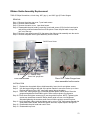
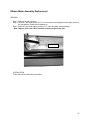
Ribbon Guide Assembly Replacement
TOOLS: Philips Screwdriver, six inch long .002” (qty-1), and .004” (qty-2) Feeler Gauges
REMOVAL
Step 1. Remove the printer top cover, 7-pan head screws.
Step 2. Remove ribbon cassette.
Step 3. Remove the carrier cover, 1-pan head screw.
Step 4. Disassemble the print head by removing 2-pan head screws (S-6) from the head carrier
and pull the printhead toward the front of the printer. Place the print head on top of the
unit, out of the way.
Step 5. Remove 2-pan head screws (S-6) that secure the ribbon guide assembly onto the carrier.
Step 6. Remove the plastic ribbon guide assembly from the carrier.
Carrier Cover Screw
Carrier Stop
Place .002” gauge here
Print Head Screws
Place .004” Feeler Gauges here
when assembled on the carrier
INSTALLATION
Step 7.
Step 8.
Replace the clear plastic ribbon shield assembly. Insert, but do not tighten screws.
Use the large white gear left side of the printer chassis to move the carrier up or down.
Position the Carrier Stop .002” (use feeler gauge) above the platen.
Step 9. Place .004” feeler gauges (qty-2) beneath the clear plastic ribbon shield. Place the
gauges alongside the metal ribbon guide. Refer to above picture for reference.
Step 10. Press down and tighten screws (qty-2) securing shield in place. NOTE: Tightening the
screws can sometimes cause the ribbon plastic guide to move out of alignment.
Alternate tightening the screws a small amount until the guide is secured in place.
Step 11. Verify the plastic ribbon guide and platen gap by using a .004” feeler gauge beneath the
clear plastic ribbon shield. Should the gap be incorrect, repeat steps #7 through #11.
Step 12. Reassemble the print head and carrier cover.
Step 13. Reassemble top cover.
52
Carriage (C) Motor Assembly Replacement
TOOL: Screwdriver
REMOVAL
Step 1. The top enclosure must be removed.
Step 2. Remove 2 pan head screws (S-17) from the mechanism stoppers left and right corners of
the printer chassis.
Step 3. Lift up the back of the mechanism and disconnect the C motor harness from the
connector on the control PCB unit. Cut and remove tie wrap from tie plate.
Step 4. Remove 4 pan head screws (S-16) from the C motor.
Step 5. Remove the screw from the return pulley bracket, pull and remove the timing belt from
the return pulley.
Step 6. Remove the C motor.
INSTALLATION
Follow the reverse of the above procedure.
Note: Place the harness back in it's original position. Secure the wire harness with a tie
wrap.
53
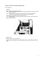
Carriage Timing belt replacement
REMOVAL
Step 1: Remove 4 captive screws securing the C motor to the motor plate, and then remove the
timing belt from the motor pulley.
Step 2: Remove the timing belt from the idler pulley assembly by simply dislocating the idler
pulley assembly from its holder.
Step 3: Remove 2 screws to separate the timing belt from the carrier assembly.
INSTALLATION
Follow the reverse of the procedure.
NOTE: When installing the timing belt on the carrier assembly, fix the teeth of the timing belt on
the teeth of the belt stopper.
54
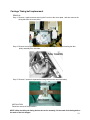
Line Feed (LF) Motor Assembly Replacement
REMOVAL
Step 1. Remove the top enclosure.
Step 2. Remove 2 pan head screws (S-17) from the mechanism stoppers left and right corners of
the mechanism. Rotate the mechanism up.
Step 3. Disconnect the LF motor harness from its connector in the control PCB unit.
Step 4. Remove LF motor timing belt.
Step 5. Remove 2 pan head screws (S-16) from the LF motor to remove the assembly.
INSTALLATION
Follow the reverse of the above procedure.
Note: Secure the wire harness with a tie wrap. Place the harness back in its original
position.
55
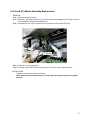
Platen Replacement
REMOVAL
Caution: avoid getting grease on the platen.
Step 1. Remove top enclosure.
Step 2. Remove 2 pan head screws (S-17) from the mechanism stoppers left and right corners of
the printer chassis. Rotate the mechanism up.
Step 3. Detach the plastic gear on the left side of the platen shaft by removing1 pan head
screw (S-16).
Step 4. Remove the E-rings (E-6) on either end of the platen shaft.
Step 5. Slide the platen to the left and then right out of the mechanism.
INSTALLATION
Follow the reverse of the above procedure.
Note: When installing the platen shaft on the mechanical block, be sure to locate the
plastic bearing with the shaft opening on top.
Friction Mechanism Replacement
This mechanism consists of pinch roller driver assembly and pinch roller driver assembly B.
Pinch roller driver Assembly
REMOVAL
Step 1. Remove top enclosure.
Step 2. Unhook the friction springs (qty-7) from the FC shaft B.
Step 3. Detach the paper feed intermediate gear on the left side of the pinch roller drive
shaft by removing 1 pan head screw (S-6); then remove the E-ring (E4) on either end of
the pinch roller drive shaft.
56
Step 4. Slide the carrier to extreme left along the F guide shaft.
Step 5. Slide the pinch roller drive shaft to the left and then right out of the mechanism.
INSTALLATION
FC Shaft
Follow the reverse of the above procedure.
Note: When installing the pinch roller shaft assembly, the "D" shape side of the shaft
is placed to the left.
Pinch roller driver Assembly B (Front)
REMOVAL
Step 1. Remove top enclosure.
Step 2. Unhook the friction spring from the FC shaft.
Step 3.Detach the paper feed shaft intermediate gear on the right side of the pinch roller drive
shaft B by removing 1 pan head screw (S-6); then remove the E-ring (E4) on either end
of the pinch roller drive shaft.
Step 4. Slide the pinch roller drive shaft to right the and then left out of the mechanical block.
INSTALLATION
Follow the reverse of the above procedure.
Note: When installing the pinch roller shaft assembly, note the "D" shape side of the shaft
is placed to the right.
57
Ribbon Motor Assembly Replacement
REMOVAL
Step 1. Remove the top enclosure.
Step 2. Remove 2 pan head screws (S-17) from the mechanism stoppers left and right corners of
the mechanism. Rotate the mechanism up.
Step 3. Remove 2 pan head tapping screws (S-11) from the ribbon motor assembly.
Note: Replace motor with cable connector located on right lower side.
Connector
INSTALLATION
Follow the reverse of the above procedure.
58
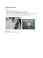
HA Motor Replacement
REMOVAL
Step 1. Remove the top enclosure.
Step 2. Remove control panel support bracket 2 pan head screws.
Step 3. Remove HA sensor-fixing plate, 1 pan head screw (S-4).
Step 4. Remove 4 pan head tapping screws (S-11) to disassemble the HA motor Fixing Plate.
Step 5. Remove the HA motor Assembly, 2 pan head tapping screws (S-11).
INSTALLATION
Follow the reverse of the above procedure.
59
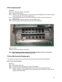
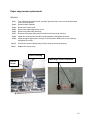
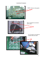
Paper edge sensor replacement
REMOVAL
Step1:
Step2:
Step4:
Step5:
Step6:
Step7:
Step8:
Step9:
Turn off the printer power switch, and then open the printer cover, move the print head
to the left of the printer.
Remove ribbon cassette.
Remove the carrier cover.
Remove the paper edge sensor cover.
Remove the paper edge sensor(s).
Disconnect the paper edge sensor connector from the carrier housing.
Install new sensor(s) into the ribbon guide assembly, and tighten the screw.
Install the paper edge sensor cover(s), route the sensor cable into the cover opening
and tighten the screw.
Step10:
Connect the sensor cable(s) plug into the socket on the carrier housing.
Step11:
Replace the carrier cover.
Carrier Housing
Paper Edge Cover & Sensors
Carrier
Cover
60
Carrier replacement
REMOVAL
Step1: Remove the F guide shaft support “E” rings (left and right), remove both support brackets,
and the springs.
Step2: Remove the F guide shaft screw, Adjust shaft and two bearings.
Step3: Remove the two HA motor screws from the fixing plate.
Step4: Remove the screws on the HA cam L/R (left and right side of the mechanism). Remove the
three cams.
61
Step5: Remove the “E” rings from inside of the F guide shaft, remove the bearings.
Step6: Remove carrier cover screws, and cover.
Step7: Remove the two print head screws and detach the print head FFC- A, B and C cables.
Step8: Remove the 4 captive screws that are holding the C motor to the fixing plate, then
remove the timing belt from the C motor pulley. Remove the screws that are holding the rear
guide to the base plate L and the base plate R. Remove the rear guide.
Step9: Remove the timing belt from the idler pulley assembly by dislocating the idler pulley
assembly from its holder.
62
Step10: Remove the carrier assembly to the left of the printer.
Step11: Remove F guide shaft from the base plate R.
INSTALLATION
Follow the reverse of the above procedure
Replacement of Sensors
(1) FC Home Sensor Assembly Replacement
FC Home Sensor Assembly consists of one FC home, and one OP home sensor located on base
plate L assembly.
REMOVAL
Step 1. Remove the top enclosure.
Step 2. Remove 2 pan head screws (S-17) from the mechanism stoppers left and right corners
of the mechanism. Rotate the mechanism up.
Step 3. Disconnect the harnesses of FC home sensor and OP home sensor on the control PCB.
Step 4. Remove the OP home sensor 2 pan head screws (S-1), cut the tie wrap.
Step 5. Remove the E-ring (E-4) to disassemble the FC reduction gear B.
Step 6. Remove the FC home sensor 2 pan head screws (S-4) from the FC home sensor.
INSTALLATION
Follow the reverse of the above procedure.
63
(2) FC Home Sensor B Assembly Replacement
FC Home Sensor B Assembly consists of one FC home, and one OP home sensor located on base
plate R assembly.
REMOVAL
Step 1. Remove the top enclosure.
Step 2. Remove 2 pan head screws (S-17) from the mechanism stoppers left and right corners
of the mechanism. Rotate the mechanism up.
Step 3. Disconnect the harnesses of FC home sensor and OP home sensor on the control PCB.
Step 4. Remove the OP home sensor, 2 pan head screws (S-1) and cutting the tie wrap.
Step 5. Remove tie plate, 4 screws.
Step 6. Remove the FC home sensor 2 pan head screws (S-4) from the FC home sensor.
INSTALLATION
Follow the reverse of the above procedure.
64
(3) Home Sensor Assembly Replacement
Home Sensor Assembly is located on the left side of the FFC bottom plate assembly.
REMOVAL
Step 1. Remove the top enclosure.
Step 2. Remove 2 pan head screws (S-17) from the mechanism stoppers left and right corners
of the mechanism. Rotate the mechanism up.
Step 3. Disconnect the home sensor harnesses on the control PCB.
Step 4. Remove the cassette holder L, 2 pan head screws (S-6).
Step 5. Detach the home sensor assembly by removing 2 pan head tapping screws (S-12).
(4) Paper Sensor Assembly Replacement
The Paper Sensor Assembly is located beneath the plastic molded metric scale (front printer view).
REMOVAL
Step 1. Remove the top enclosure.
Step 2. Remove 2 pan head screws (S-17) from the mechanism stoppers left and right corners
of the mechanism. Rotate the mechanism up.
Step 3. Disconnect the harness of the paper sensor assembly on the control PCB.
Step 4. Remove the metric scale, 4 pan head tapping screws (S-12).
Step 5. Detach the Paper sensor assembly by removing 1 screw (S-13).
INSTALLATION
Follow the reverse of the above procedure.
65
(5) Paper Edge Sensor Replacement
The Paper Edge Sensor is located on the ribbon guide assembly.
REMOVAL
Step 1. Remove the carrier cover, 1 pan head screw (S-6).
Step 2. Disconnect the harnesses of the paper edge sensor from the head connecting PWB.
Step 3. Open the paper edge sensor cover by removing 1 pan head tapping screw (S-19).
INSTALLATION
Follow the reverse of the above procedure.
(6) Sensor Harness A Replacement
The Sensor Harness A Assembly is located beneath the plastic molded metric scale (front
printer view). The sensor is functional when the cover is opened.
REMOVAL
Step 1. Remove the top enclosure.
Step 2. Remove 2 pan head screws (S-17) from the mechanism stoppers left and right corners
of the mechanism. Rotate the mechanism up.
Step 3. Remove the paper cutter cover, 4 pan head tapping screws (S-12).
Step 4. Disconnect the connector for the sensor harness A assembly on the control PCB.
Step 5. Detach the sensor harness A assembly by removing the retaining screw (S-13).
INSTALLATION
Follow the reverse of the above procedure.
(7) HA Sensor Assembly Replacement
REMOVAL
Step 1. Remove the top enclosure.
Step 2. Remove 2 pan head screws (S-17) from the mechanism stoppers left and right corners
of the mechanism. Rotate the mechanism up.
Step 3. Disconnect the HA sensor assembly harness on the control PCB.
Step 4. Detach the HA sensor assembly by removing 2 pan head tapping screws (S-3).
INSTALLATION
Follow the reverse of the above procedure.
66
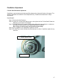
Parallelism Adjustment
F Guide Shaft Parallelism Adjustment
Parallelism is required when print darkness differs between the right and left sides of the paper. The
following adjustment is intended for minor adjustment only. Contact the manufacturer for major
adjustments.
PROCEDURE:
Step 1: Remove the Top Enclosure.
Step 2: Loosen the F Guide Shaft Adjust screw on the right end of the F Guide Shaft. Rotate the
Shaft nut no more than 1/8” clockwise.
Step 3: Print Self-Test to verify contrast. When printing without the top enclosure on, make sure
the Interlock Switch and the Cover Open/Close Switch are closed.
Note: Keep your hands away from the head during printing.
Step 4: Upon completion of the adjustment, tighten the screw.
Step 5: Run Self-Test to check whether the print darkness is uniform. If satisfied, replace the top
enclosure.
F Guide Adjust Shaft
Adjust Screw
67
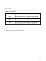
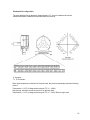
Lubrication
The manufacture specified lubricants should be used. Their usage and applicable areas are
specified in the Exploded View.
Part Numbers
Description
EM60L
Apply between plastic parts, such as gears and pinch roller holder.
SFP-6
Apply between the metal and plastic parts such as a gear and lever
axle (metal stud).
HV#22
This lubricant (oil) is durable in temperature and is used for the
carriage assembly. Main shaft and carriage felt washers.
*Refer to the next page for lubrication examples.
68
Lubrication Examples
??????
G52
G39
G51
EM60L, between mating gears.
G50
G38
G43
G37
G36
G40
SFP-6, between the metal and
plastic parts.
HV-22, applied to carriage felt
washers and main shaft.
69
Electronic Repairs
Introduction
This section will limit the explanation to the operational principles of the circuitry.
The Cable Connection table below shows the interface of the electronic assembly with the
mechanical assembly. You may be able to check the possibility of the connection faults or the
mechanical defects at this point.
Main PCB
Main PCB
Name of PCB: FP6000K-01VB
PCBA parts
CPU MB90705H(25 MHz), QFP, 120pin
EEPROM(2k bits), SOP, 8pin
Gate array BBG010(12.5MHz), QFP, 120pin
Gate array BBG020(12.5MHz), QFP, 100pin
Gate array BBG030(12.5MHz), QFP, 100pin
Reset circuit
MC motor drive circuit (4 circuit)
Head Adjust motor drive circuit
Ribbon motor drive circuit
C motor drive circuit
LF motor drive circuit (2 circuit)
Pin drive circuit
Detector
CPU MB90705H
QFP,120 pin, Acts with 12.5 MHz(input oscillation frequency is 25 MHz), Data bus width is 8 bit
and uses addresses A0-A22.
Main Function
Controlling indicator
Controlling and observing sensors
Data transmitting and receiving of serial interface
Analyzing data
DRAM control
Controlling LF motor rotation
70
Port Explanation
(1) X0,X1(Input): Terminal for oscillator (25 MHz)
(2) XRESET(Input): Reset signal input.
(3) A0-A22(Output): Address bus.
(4) D0-D7(I/O): Data bus.
(5) XRD, XWR(Output): Read signal, write signal.
(6) A19/A18, A17/A16(Output): Address for DRAM.
(7) XRAS, XCAS(Output): Signal for DRAM control.
(8) SYSCLK (Output):12.5 MHz (Original oscillation frequency of 25 MHz is divided into 2).
(9) HRQ(Input), XHAK(Output): DMA request, hold acknowledge. Refer to DMA item for details.
(10) Interrupt input(All input)
INT0: HA encoder input
INT1: Home sensor input
INT2: HA encoder input
INT3: Sensor interrupt input (For detection by tractor sensor, home sensor and cover open)
DRE0: Power cutoff input
DRE1: Centronics interface initial interrupt input
DRE2: Centronics interface data receiving interrupt input
DRE3: C motor position interrupt input
(11) XCS03(Output): Chip select output to gate array BBG030
(12) SCK0(Input): Basic clock input for serial transmitting and receiving signal
(13) SIN0(Input): SOUT0(Output): Data input and output of serial data interface.
(14) PB0-PB3: connect with EEPROM. Refer to EEPROM item for details.
(15) Analog input
AN0: Detection of head temperature
AN1: Detection of Jam sensor (front/rear)
AN2: Detection of paper edge
AN3: Detection of paper sensor, skew sensor and slide volume
(16) P11-P17: LCD data bus.
(17) P50, P53, P61, P65: LCD control.
(18) TOUT0(Output): Clock output for LF motor drive
(19) TOUT1(Output): Clock for C motor drive
71
● MB90705H pin assignment
EEPROM CAT93C56J
EEPROM of serial I/O of SOP, 8 pin, 2k bits.
Main Function
Maintains printer setup data (information including number of print lines, margins, starting
position for printing and lateral alignment). Data is read when power is turned on, and data is
written at setup and when power is turned off.
72
Terminals Explanation:
D0 (Output):
Data output. Connect with PB3 of CPU.
D1 (Input):
Data input. Connect with PB1 of CPU.
CS (Input):
Chip select. Active when "High". Connect with PB2 of CPU.
CLK (Input):
Clock for write/access data. Connect with PB0 of CPU.
Gate array BBG010
QFP, 120 pin. Acts at 12.5 MHz. Access is possible with addresses 100000h-10003Fh.
Main function
Pin Drive Waveform Creation
Chip select output(Control, font ROM and BBG020)
DMA controller(For printing data transmission)
● BBG010 pin assignment
73
Port Explanation
(1) AL0-AL5(Input): Address input.
(2) AM8-AM15(3 state): Output address to DRAM for DMA.
(3) DRA8, DRA9(3 state) Output address to DRAM for DMA.
(4) AH18-AH22(Input) Address input.
(5) D0-D7(I/O): Data bus.
(6) XRD, XWR(Input): Read signal, write signal.
(7) XRAS, XCAS(3 state): Control access to DRAM of DMA.
(8) XRCONT(Output): Chip select for control ROM.
(9) XROPT(Output): Chip select for Option font ROM.
(10) XRFONT(Output): Chip select for font ROM.
(11) XGA2(Output): Chip select for BBG020.
(12) HREQ(Output): XHAK(Input): For DMA request and DMA start.
(13) INTHC(Input): To inhibit pin action at C motor position interrupt.
(14) SYNC(Input): For start timing of printing.
(15) SYSCLK(Input): 12.5 MHz clock.
(16) XRESET(Input): Reset signal.
(17) PINA1-24(Output, open drain): Pin waveform output.
Gate array BBG020
QFP, 100pin. Acts at 12.5 MHz. Access is possible with addresses 140000h-14003Fh.
Main Function
Controlling C motor rotation
Controlling LF motor rotation
Controlling ribbon motor rotation
Controlling head adjust motor rotation
Controlling MC motor rotation
Sensor interrupt output
C motor position interrupt output
Paper sensor input
Home sensor input
Cover open A input
Sensor input control
Buzzer control
74
● BBG020 pin assignment
Port Explanation
(1) A0-A5 (Input): Address bus.
(2) D0-D7 (I/O): Data bus.
(3) XCSIN (Input): Chip select.
(4) XRD, XWR (Input): Read signal, write signal.
(5) IREQ1 (Output): This signal turns to "High" at sensor interrupt. Refer to CPU INT3 item.
(6) DS1, 4, 5(Input): Sensor input.
(7) AUXO1-3 (Output): For setting LF motor current.
(8) SYNC0 (Input): Clock for C motor rotation, detects the edge of this signal and turns C motor.
(9) SYNC1 (Input): Clock for LF motor rotation. Detects the edge of this signal and turns LF
motor.
(10) BUZZ (Output): Signal for piezoelectric buzzer drive.
(11) HCA, HCB, HCXA, HCXB (Output, open-drain): Signal for C motor drive.
(12) HCDR0-4(Output): For setting C motor current.
(13) LFA, LFB, LFXA, LFXB (Output, open-drain): Signal for LF motor drive.
(14) LFDR0-LFDR2 (Output): For setting LF motor current.
(15) RBA, RBB, RBXA, RBXB (Output, open-drain): Signal for Ribbon motor drive.
(16) RBDR0-RBDR1 (Output): For setting ribbon motor current.
(17) HAA, HAB, HAXA, HAXB (Output, open-drain): Signal for HA motor drive.
(18) HADRO (Output): For setting HA motor current.
(19) MCA, MCB, MCXA, MCXB (Output, open-drain): Signal for MC motor drive.
(20) XRESET (Input): Reset signal.
(21) XIN(Input): 12.5 MHz clock.
Gate array BBG030
QFP, 100pin. Acts at 12.5 MHz. Access is possible with addresses 0000C0h-0000FFh.
75
Main Function
Controls centronics I/F
Controls serial I/F
Port Explanation
(1) A0-A5(Input): Address bus.
(2) D0-D7(I/O): Data bus.
(3) XCSIN(Input): Chip select.
(4) XRD, XWR(Input): Read signal, write signal.
(5) INTREQ(Output): "High" for centronics I/F initial input.
(6) DTXREQ(Output): "High" for centronics I/F data input.
(7) SYNC0(Input): 12.5 MHz clock.
(8) SYNC2(Output): Clock for serial I/F baud setting.
(9) CDATA0-7(Input): Centronics I/F data input.
(10) XACK, BUSY, POUT, XERR, SLCTOUT(Output): Centronics I/F signal.
(11) XSTB, XATFD, XINIT, XSLCTIN(Input): Centronics I/F signal.
(12) DTR(Output): Serial I/F signal.
(13) CTS(Input): Serial I/F signal.
(14) SWCLK, SWLTCH(Output): For detection of Panel key.
(15) SWIN(Input): For detection of Panel key.
(16) ENCODE2-3(Input): For detection of HA encoder.
76
● BBG030 pin assignment
Regarding DMA
BBG010 transfers printing data to BBG010 directly by DMA from DRAM without going
through the CPU in order to transmit data developed in DRAM to BBG010 from DRAM at
high speed (DMA: Direct Memory Access). The following is an explanation of this process.
1. The CPU gives the first address of pin cycle, pin drive time, printing direction and pin
buffer and moves the C motor for the head to reach printing position. When the LFCK
signal is turned 0 → 1 → 0 or 1 → 0 → 1 (one of these will be selected according to
printing direction), printing starts.
2. Dot timing of the leading pin starts at the first edge of LFCK and dot timing of the next
successive pin starts at next edge. This dot timing refers to the time that it takes the
carriage head to move 1/720 inch.
3. DMA is operated according to the dot timing of each successive pin.
3.1 HRQ of BBG010 becomes "High".
3.2 When the CPU acknowledges hold (bus is released), XHAK becomes "High".
3.3 BBG010 transfers printing data to the printing buffer in BBG010 from 6 bytes of
DRAM.
3.4 After transferring data, BBG010 turns HRQ to "Low".
3.5 The CPU operates and XHAK becomes "High".
4. DMA repeats dot timing cycle until printing is completed.
77
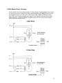
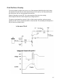
HA Motor Driver Circuitry
The HA motor is a 4-phase stepper motor, driven by double-phase, and controlled by BBG020.
During standby, transistor Q7 is turned OFF and the HA motor is supplied with standby current
from the 40 V power line through R209. This standby current is necessary to stop the HA motor
smoothly.
When the HADR0 signal (U24/28) goes HIGH, current is supplied to the HA motor through Q7.
Thereafter, each phase is turned ON or OFF, in turn, to revolve the HA motor.
78
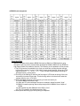
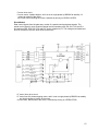
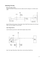
Ribbon Motor Driver Circuitry
The ribbon motor is a 4-phase stepper motor, driven by double-phase, and controlled by
BBG020.
During standby, transistor Q5 is turned OFF and Q6 is turned ON so that the ribbon motor is
supplied with standby current from the 40 V power line through R205 and R207. This standby
current is necessary to stop the ribbon motor smoothly.
When the RBDR0 signal(U24/24) goes HIGH, current is supplied to the ribbon motor through
Q5. Thereafter, each phase is turned ON or OFF, in turn, to revolve the ribbon motor.
79
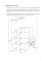
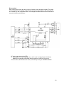
MC Motor Driver Circuitry
The MC motors are 4-phase stepper motors, driven by double-phase, and controlled by
BBG020.
There are four MC motors: MC1 to MC4. To select a motor to operate, set the motor’s
corresponding signal of MCON1 through MCON4 to HIGH. Only one motor may be operated at
a single time; it is impossible to simultaneously run two or more motors.
80
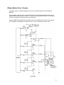
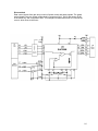
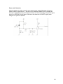
LF/HC Motor Driver Circuitry
The line feed (LF) motor and head carriage (C) motor are both a 4-phase stepper motor, driven
by 1/2 phase (C motor) or 2-phase (LF Motor), and controlled by U24 (BBG020) and U1(CPU).
The signals (LF motor: LFA, LFB, XLFA, XLFB, LFBA, LFBB, LFBXA, LFBXB and C motor.
HCA, HCB, XHCA, XHCB) are phase drive signals, which controls the direction and the step
width of the motor. LFDR0-2, LFBDR0-2, HCDR0-4, and HCST are current control signals,
which controls the speed of motor.
81
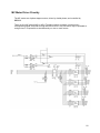
C motor drive circuit
C motor uses a 4-phase stepper, and it is set in single phase by BBG020 at standby 1/2phase at rotation of the motor.
The current value reaching the motor is decided by turning on HCDR0–HCDR4.
Drive Method
Data control signals from the gate array consist of a speed control and phase signals. The
speed control signal is set at a certain voltage level by transistors Q8, Q9, Q10, Q12 and Q11
and resistors R58, R59, R60, R76 and R61, and is supplied to P2. This voltage level determines
how P2 controls the current, which flows to the motor.
LF motor (front) drive circuit
LF motor uses a 4-phase stepping motor, and it is set in single phase by BBG020 at standby
and double phase at rotation of the motor.
Current value, which flows to the motor, is decided by turning on LFDR0-LFDR2.
82
Drive method
Data control signals from gate array consist of speed control and phase signals. The speed
control signal is set at a certain voltage level by transistors QA10, QA11 and resistor R167,
R172 and R179, and is supplied to U22. This voltage level determines how U22 controls the
current, which flows to the motor.
LF motor (rear) drive circuit (LFB)
LF motor uses a 4-phase stepping motor, and it is set in single-phase excitation by
MB90705H at standby and double phase excitation at rotation of the motor.
Current value, which flows to the motor, is decided by turning on LFBDR0-LFBDR2.
83
Drive method
Data control signals from gate array consist of speed control and phase signals. The speed
control signal is set at a certain voltage level by transistors QA11, QA12 and resistor R180,
R182 and R183, and is supplied to U23. This voltage level determines how U23 controls the
current, which flows to the motor.
84
Print Pin Driver Circuitry
The control signal from Gate Array turns on or off the transistors SMA5106 (QA1-QA6). When
the transistor is turned ON, the current starts flowing out of the print pin coil and producing the
pin striking force due to a electromagnetic phenomenon.
When the transistor is turned OFF, the current persists to flow due to the existing
electromagnetic field and creates negative high voltage at point A.
The print pin is activated for a period of 120µ to 128µ seconds, and then continues several
repetition of OFF for 3.2µ seconds and ON for 19.2µ seconds. The activated period depends on
the print density (multipart mode).
85
Printhead Pin Configuration
The print head has 32 pin terminals. Approximately 14.7 ohms of resistance should be
measured between COMMON terminal and each pin terminal.
C: Common
T1, T2:Thermistor
When high temperature is detected in the print head, the printer automatically takes the following
actions:
Temperature > 115°C (Voltage at the test point TP 11 > 3.98V)
Stop printing, and then moves the carrier in full printing width.
Temperature > 110°C (Voltage at the test point TP 11 > 3.85V) Reverse logic seek
86
Detecting Circuitry
MC sensor (Rear tractor)
When the rear tractor is selected, the micro switch turns ON, causing No. 12 of U20 to set to
LOW.
Note: MC Sensor (Front tractor), Tractor Paper Sensor (Rear/Front) belong to this circuit type.
Refer to the circuit diagram for those details.
Paper Empty Detector
A photo-reflector type sensor is used to detect a paper empty condition.
Note: Circuit type: Edge Sensor ,Skew Sensor and Jam Sensor (Rear/Front)
87
Power cutoff detection
When the power of the CPU is cutoff or 40 V system power voltage falls below 30 V due to
trouble, PWOFF signal turns to "1" and the CPU is interrupted. When the CPU accepts this
interrupt, it finishes all printing and mechanical action and writes necessary data (present paper
position) to EEPROM. During approx. 500 msec. after detection of PWOFF signal, power
voltage of 5 V system is assured.
88
Home Sensor
A photo-interrupter type sensor is used to detect a carrier position. If the voltage level at HS
(U24/ 70) is LOW, the printer detects the carrier at home position. If the carrier is out of the
home position, the voltage level is HIGH.
Note: Circuit type: Head Adjust Sensor, Cover Open Sensor and Mc Sensor (front/rear friction)
89
Power Supply PCB
Outline
This is a self-oscillating, RCC type switching power supply circuit. The output voltage is
controlled by the switching frequency. The rated input is 120V, 60Hz for U.S.A. and 100V for
JAPAN setting (adding to the Jumper at CN2) and 230V, 50Hz for European setting (Removing
the Jumper at CN2). The output voltages are +40V, and +5V. To stabilize the output voltages,
the switching frequency of the HIC (P1) in the primary circuitry is controlled by the signal feed
back from the +40V output voltage detection circuitry through the photo-coupler (PC2).
Operations
See the voltage waveform and circuit diagrams.
(1) Power switch is turned on.
(2) The DC voltage Vin is converted through the rectifying circuitry (DB1, L2, C7, C8) and is
supplied to the HIC (P1) through initial one-time flow resistor (R5). The P1 starts oscillating
when the 4 pin of P1 reaches 16V.
(3) Initiated by the oscillation of P1, the Power MOSFET (in P1) is turned ON, then the current
starts flowing through C7 (+) → TR1 (5→2) → P1 (4→2) → R2 → C8 (-).
(4) The drain current at P1 increases in proportion to the ON time interval of P1 due to the
transformer (TR1) inductance.
(5) When P1 is ON and the current flows in the primary coil (5-2) of the transformer (TR1), the
voltage is generated on the control coil (6-7) of the TR1. The voltage is rectified through D2
and C11 and is supplied to the Vcc of the P1 at approximately 20V to sustain the oscillation
in P1. At that time, the voltages for 40V is also generated in the secondary coil (12,13-15,16)
of the TR1.
(6) The voltage in the secondary coil (12,13) is rectified through the diode D7 and smoothed by
C16 and C17.
(7) When the voltage exceeds +40V in the output and reaches over the rated value of the Zener
diode (ZD5) at the voltage level divided down by the ratio of R19 and R20, the transistorQ1)
is turned on. Simultaneously, the photo-couplerPC2) is turned on. Consequently it increases
the voltage on OCP/FB1 pin) of P1 and the switching frequency of P1, and it decreases the
output voltages. When the output voltages decrease below 40V the PC2 is turned off. It in
turn, increases the output voltages.
(8) By the repetition of the process at step 7 above, +40V output voltage is stabilized. Because
the current flow in the PC2 responds linearly and inversely proportional to the load, the
switching frequency of the P1 is controlled to stabilize at the +40V output.
(9) +5V output voltage is also leveled to a constant value by the chopper operation in the
regulator IC (P2) and smoothing circuit. +40V output voltage flows into P2 and generates a
square waveform with a different duty ratio by the switching on and off operation (chopper
operation). These square waves are flattened and smoothed out to be in 5V voltage level in
the rectifying circuitry
90
Troubleshooting flow
Power Supply PCB Troubleshooting flow.
When the power switch is turned on.
Is AC power cord properly attached?
• Turn the power switch off then reinstall the power cord again.
Fuse blown?
• Check the jumper of CN2 (for 100V/120V model).
• Check fuses (F1, F2) on the power PCB.
Check the output voltage on the secondary circuit on the Power Supply PCB.
• Test points for those output voltage are located near the Capacitor C16.
Test Point
Ground
Location
Heat sink panel of D7
+40V
+5V
Lead of FB2
Lead of FB3
Caution:
Do not cross the test point with the ground line on the PCB. A short may
damage the component.
Check the appearance of the components for any abnormality.
Note:
Basically when troubleshooting the target device, the device must be
isolated from other device. User the proper loads for the device to obtain the
correct measures.
Load in condition of printer
Standby
"K" character printing
Current Consumption
40V
5V
0.5A
3A
600mA
600mA
Current Consumption
91
(First, check 40V-generating circuit, because +5V is regulated from the 40V
output.)
If using a “X100” attenuator built-in probe, check the waveform at 200KHz
frequency between the drain of P1 and primary GND (heat sink panel of P1).
Else check all following possibilities.
P1 OK?
•
Check the resistance between the drain and source of P1. Make sure
it is not shorted.
P1 OK?
Check the waveform at pin 3 of P1.
R4, R5 OK? If not, replace.
SCR1, SCR2 OK? If not, replace.
PC2, Q1, ZD2, ZD5, ZD4, R19, R20 OK? If not, replace.
If still no 40V, consult your dealer.
F2 fuse, P2, ZD3 OK? If not, replace
If no +5V, check FB3.
If still no +5V, consult your dealer.
92
Indicator Circuit
93
I/F Circuit
94
Slide SW Circuit
95
Power Circuit
96
Exploded View (1/6)
Following pages require
Legal size paper for
printing.
97
Exploded View (2/6)
98
Exploded View (3/6)
99
Exploded View (4/6)
100
Exploded View (5/6)
101
Exploded View (6/6)
102
Assemblies
Reference
Number
N104-4000
N104-205U
N104-6040A
95150-239A
N104-263A
95150-093A
95150
95150-5001A
N104-5014A
95150
95150
Part
Number
130407
130414
130403
130413
130404
130418
SAP
1~177
1~178
1~179
1~162
1~172
1~164
1~168
1~121
1~112
Parts Name
Mechanism
Paper Rack
Tractor Unit
Indicator House Assembly
I/F PCB Assembly
Slide SW Cover Assembly
External Electric
Main PCB Assembly
Power Supply PCB Assembly
Enclosure
Packing
QTY
1
1
1
1
1
1
1
1
1
1
1
Mechanism Material
PART NO.: N104-4000 SAP: 100000000177
Reference
Number
N104-001A
N104-002A
N104-003
N104-004
N104-005
N104-006A
N104-026
N104-027
N104-029
N104-030
N104-032
N104-033
N104-034
N104-036
N104-037
N104-037B
N104-038
N104-039
N104-040
N104-042
N104-043
N104-044
N104-045
N104-046
N104-047
N104-048
N104-049
N104-050
N104-051
N104-052
N104-053
N104-054
N104-055
N104-056
N104-057
N104-058
N104-059
N104-060
N104-061
N104-062
N104-063
N104-064
N104-065A
N104-066A
Part
Number
130456
130457
130402
130464
SAP
4615
4724
4787
4800
4802
4671
4806
4832
4804
4808
4847
4850
4851
4842
4856
4844
4858
4857
4841
4859
4846
4814
4825
4831
4833
4820
4838
4855
4854
4853
4816
4809
4811
4823
4818
4687
4690
4861
4862
4863
4864
4883
4865
4884
Parts Name
Base Plate R Assembly
Base Plate L Assembly
Paper Guide
Paper Guide B
Paper Guide C
LF Motor Assembly
NMB
Platen Bearing
Bearing 6
Platen
Paper Feed Shaft
Platen Gear
Platen Intermediate Gear
Platen Reduction Gear
Reduction Gear B
Intermediate Gear C
Compression Spring
OP Reduction Gear
OP Gear
OP Switching Cam
Gear Cover
Intermediate Gear
Pinch Roller Drive Shaft
Pinch Roller Drive Shaft B
Cam Shaft
Cam Shaft B
FC Shaft
FC Shaft B
Paper Feed Shaft Gear
Paper Feed Shaft Intermediate Gear B
Paper Feed Shaft Intermediate Gear
Pinch Roller Transmitting Gear
Pinch Roller
Pinch Roller Holder
Pinch Roller Holder B
Pinch Roller Bearing
FC Shaft Guide
FC Shaft Guide B
FC Reduction Gear
FC Reduction Gear B
FC Intermediate Gear
FC Cam L
FC Cam R
FC Arm L Assy
FC Arm R Assy
QTY/
Assy
QTY
1
1
1
1
1
2
2
4
1
2
1
1
1
2
2
2
2
2
2
1
2
1
1
1
1
1
1
2
2
2
14
14
7
7
4
2
2
1
1
1
1
1
1
1
111
N104-067A
N104-067BA
N104-068
N104-069
N104-070
N104-071
N104-072
N104-073
N104-074A
N104-075A
N104-077
N104-078
N104-079
N104-080
N104-082
N104-082B
N104-088A
N104-088BA
N104-090
N104-091
N104-094
N104-096A
N104-099
N104-100
N104-101
N104-102A
N104-103
N104-104
N104-105
N104-107
N104-108
N104-110
N104-112A
N104-114
N104-117A
N104-116
N104-124
N104-118
N104-119
N104-120
N104-121
N104-122
N104-123
N104-124B
N104-124C
N104-125A
N104-126
N104-127
N104-130
N104-131
N104-132A
N104-133
N104-134A
N104-136A
N104-137
N104-140
N104-141
N104-142
N104-143
N104-144
N104-145A
N104-147
N104-148A
N104-149
N104-151
N104-152
N104-153B
N104-156A
130408
130428
130436
130435
130410
130411
130419
130454
130421
130437
130429
130440
1~180
1~181
4860
4812
4887
4888
4890
4868
4891
4869
4882
4830
4685
4894
4785
4718
4793
4640
4613
4607
4604
1~182
5533
4681
4900
4914
4895
4906
4907
4905
4896
4897
1~183
4898
1~184
4502
4696
4521
4491
4902
4901
4903
4899
4735
7322
4461
4904
4458
4525
4528
4931
4941
4677
1~185
4940
4445
4929
4449
4454
4928
4944
4441
4909
4908
4913
4912
6544
4919
FC Home Sensor Assy
FC Home Sensor B Assy
FC Home Sensor Fixing Plate
Friction Spring 2
FC Reduction Gear C
FC Intermediate Gear B
FC Cam BR
FC Cam BL
FC Arm BR Assy
FC Arm BL Assy
FC Home Sensor B Fixing Plate
Friction Spring B
Plug Fixing Plate
ROM Cover
Edge Guard
Edge Guard B
Sensor Harness Assembly
Sensor Harness B Assembly
Paper Cutter Cover
Paper Cutter
Paper Sensor Cover
Paper Sensor Assembly
Carrier Damper
Carrier Stopper Spacer
Rear Guide
Carrier Assembly
F Guide Shaft
HA Cam L
HA Cam R
HA Cam Shaft
F Guide Shaft Bearing
Bearing L-1280ZZ (NMB)
HA Motor Assembly
Bearing 608ZZ (NMB)
HA Sensor Assembly
HA Sensor /GP1A13R(SHARP)
HA Home Sensor /GP1S51V(SHARP)
HA Sensor Fixing Plate
HA Motor Fixing Plate
F Guide Shaft Support R
F Guide Shaft Support L
F Guide Spring
F Guide Shaft Adjust Shaft
Wave washer 8
F Guide Spacer
HA Home Sensor Fixing Plate Assembly
HA Cam Bearing
Indicator Stand
Cassette Holder R
Cassette Holder L
FFC Bottom Plate Assembly
Ribbon Shaft Plate
Ribbon Motor Assembly
NMB
Ribbon Drive Driving Shaft Assembly
Ribbon Drive Gear
C Motor
Belt Stopper
C Motor Pulley
C Motor Fixing Plate
Timing Belt
Pulley Assembly
Pulley Shaft
Pulley Shaft Fixing Plate Assembly
Pulley Receive Plate
RT Spring
Spring Support Plate
Rear Guide Slider
Carrier Support Plate Assembly
1
1
1
7
1
1
1
1
1
1
1
1
2
1
1
2
1
1
1
1
1
1
2
1
1
1
1
1
2
1
2
2
1
2
1
1
1
1
1
1
1
2
1
1
1
1
2
1
1
1
1
1
5
1
1
1
1
1
1
1
1
1
1
1
1
1
2
1
112
N104-156B
N104-157
N104-158A
N104-159
N104-160A
N104-160
N104-162
N104-161
N104-163A
N104-163
N104-163B
N104-165
N104-165B
N104-166
N104-167
N104-168
N104-170
N104-171
130438
130459
4867
4923
1~186
4927
1~187
4653
4654
4679
1~188
4396
4789
4674
4678
4629
4584
4573
4930
4569
N104-172
130425
4544
N104-173
130426
4550
N104-174
130427
4555
N104-175
N104-176A
N104-177
N104-178
N104-179
N104-180B
N104-180
N104-181
N104-187
N104-188
N104-189
N104-197A
N104-197BA
N104-198
N104-217A
N104-217
N104-218A
N104-221A
N104-220
N104-221
N104-222
N104-223
N104-232A
N104-224
N104-225
N104-250
N104-251
N104-257
N104-270
N104-271
N104-272
N104-274
N104-275
N104-276
N104-281
N104-282
N104-8000
N104-803
84500-5409
130458
4559
1~189
4576
4580
4566
4926
4925
4624
4626
4619
4617
4754
4658
4668
1~190
4691
4694
1~191
4714
4717
4719
4721
1~192
4650
4648
4633
4637
6542
5378
5379
4456
5841
6292
6293
6983
6984
4620
6541
6403
6404
130409
130401
130463
130434
130406
130453
130465
130433
130424
130423
130412
130400
Rear Guide Roller Spacer
Carrier Sprint
Home Sensor Assembly
Home Sensor Cutoff Plate
Ribbon Guide Assembly
Ribbon Guide
Ribbon Mask
Carrier Stopper
Paper Edge Sensor Assembly
Paper Edge Sensor / GP2S40(SHARP)
Paper Guide Seal
Paper Edge Sensor Cover
Paper Edge Sensor Cover B
Flap Spring
Carrier Cover
FFC Holder B
FFC Guide Plate
FFC Cover
Head FFC-C/TW-VFM-80.035,0.8(FUJIKURA)
Head FFC-B/TW-VFM-170.035,0.8(FUJIKURA)
Head FFC-A/TW-VFM-150.035,0.8(FUJIKURA)
FFC Holder
Head Connecting PWB Assembly
FFC Upper Plate
Tie Plate
FFC Safety Sheet
Felt Cover
Ring Felt
Flap C
Flap Shaft
Flap B
Flap
RU Lock Plate L Assembly
RU Lock Plate R Assembly
RU Lock Spring
I Base Plate Assembly
I Base Plate
Interlock Harness A Assembly
Change Lever Assembly
C Base Plate
Change Lever
C Cover
Spring A
Sensor Harness A Assembly
Rubber A
Rubber B
Side Plate R
Side Plate L
HA Adjust Label
Ground spring
Ground plate
Ground spring B
Ground spring C
Ground spring D
Shield cover
Sound-absorbing Sheet C
Sound-absorbing Sheet D
Print Head
Head Cover
Binder
Binder
1
1
1
1
1
1
1
1
2
2
2
1
1
2
1
2
1
1
1
1
1
1
1
1
1
1
2
2
1
1
1
3
1
1
2
1
1
1
1
1
1
1
1
1
2
2
1
1
1
1
1
1
2
2
3
1
1
1
1
8
11
113
Paper Rack
PART NO.: N104-205U SAP: 100000000178
Reference
Number
N104-193
N104-199U
N104-190BA
Part
Number
130415
N104-191
N104-192BA
N104-199
N104-200U
N104-190A
SAP
5376
1~193
4537
4558
4549
130416
4535
1~194
4564
N104-191
N104-192A
4558
4579
N104-200
N104-205A
N104-205
N104-206
N104-207
N104-208
N104-258
N104-259
4563
1~195
4597
4601
4605
4608
6534
6535
Parts Name
QTY/
Assy
RU Removable Lever
Rack Cover R Unit
RU Holding Plate R
Assembly
RU Support Plate
Tractor Support Plate R
Assembly
Rack Cover R
Rack Cover L Unit
RU Holding Plate L
Assembly
RU Support Plate
Tractor Support Plate L
Assembly
Rack Cover L
Paper Rack Assembly
Paper Rack
Sheet Guide
Sheet Guide B
Paper Support
Remove Label
Remove Label B
QTY
1
1
1
1
1
1
1
1
1
1
1
1
1
1
1
2
1
1
Tractor Assembly
PART NO.: N104-6040A SAP: 100000000179
Reference
Number
N104-255
N104-256
N104-301
N104-302
N104-303
N104-304
N104-305
N104-306
N104-307
N104-308
N104-309A
N104-310
N104-311
N104-312
N104-312A
N104-314
N104-314A
N104-315
N104-322
N104-324
N104K-M02
N104K-M08
N104K-M10
N104K-M11
N104K-M12
Part
Number
130455
SAP
6538
6537
4424
4425
4364
4367
4373
4426
4421
4422
1~198
4385
4402
4388
1~199
4394
1~200
4406
6506
4398
4379
4386
4408
4413
4414
4382
4383
4390
4391
6404
Parts Name
TR Caution Label
TR Position Label
Tractor Cover L
Tractor Cover R
Tractor plate
Tractor shaft
Tractor Guide Shaft
Tractor Guide B
Tractor Bearing
Tractor Gear
Tractor R Assembly
Tractor Sub Frame L
Tractor sensor Frame
Tractor Lid L R
Tractor L Assembly
Tractor sensor PCB
Tractor sensor PCB
Assembly
Tractor sensor Cover
Tractor PCB Cover
Tractor Paper Sensor
Tractor Main Frame L
Tractor Knob L
Tractor Main Frame R
Tractor Sub Frame R
Tractor Knob R
Tractor Pulley
Tractor Driving Belt
Tractor Pin
Tractor Spring
Binder
QTY/
Assy
QTY
1
2
1
1
2
1
2
2
2
1
1
1
1
2
1
1
1
1
1
1
1
1
1
1
1
2
2
4
2
1
114
Indicator House Assembly
PART NO.:95150-239A SAP: 100000000162
Reference
Number
N104P-252
N104P-239
N104P-238
N104P-4722
N104P-127
N104P-4749
N104P-1953
N104P236A
N104P-4757
N104P262A
N104P-4776
84090-7233
N104P-4779
N104P-4781
N104P-3049
N104P-4786
N104P-2831
N104P-4790
N104P-4792
N104P-4794
N104P-4796
84092-4611
N104P-4798
N104P-4799
Part
Number
SAP
Parts Name
4726
4731
4744
4722
4747
4749
1953
1~173
Indicator Plate
Indicator House
LCD Cover
Screw
Indicator Stand
Screw
Hexagon Nut M2
LCD Ass'y
4757
1~174
LCD Module
Indicator PCB
Ass’y
74LS166A(IC)
Transistor
LED
LED
Carbon Res.
Carbon Res.
Res. Array
Res. Array
Ceramic Cap.
Ceramic Cap.
Ceramic Cap.
Switch
Connector
Buzzer
4776
4778
4779
4781
3049
4786
2831
4790
4792
4794
4796
4797
4798
4799
Specification/Model
Location
QTY
1
1
1
4
1
2
2
1
P.H.T. Screw(BT)3*12
P.H.T. Screw M2*10
KONXX-3001-G
LCD
1
1
74LS166A
DTC114ES TP
573AD(AWBER)
573GD(GREEN)
470ohm,1/6W,+/-5%
2.2kohm,1/6W,+/-5%
100ohm,1/8W,+/-5%
2.2kohm,1/8W,+/-5%
100pF,50V,+/-10%
1000pF,50V,+/-10%
0.1uF,16V,+/-10%
SOA-212HS
XX6216 012 110 808
KBS-20DB-4P-0
U1
Q1
LED1
LED2,3,4
R1
R2
RA2,RA3
RA1
C10,C11
C2~C9
C1
SW1~SW8
CN1
BZ1
1
1
1
3
1
1
2
1
2
8
1
8
1
1
I/F PCB Assembly
PART NO.:95150-263A SAP: 100000000172
Reference
Number
N104P-4803
84092-20001
N104P-4059
N104P-4060
84092-0089
Part
Number
SAP
Parts Name
4803
4056
4059
4060
4055
Connector
Connector
Lack Screw
Spring Washer
Connector
N104-230A
N104P-4807
N104P-4810
N104P-4532
N104P-4758
N104P-7000
N104P-4622
1~175
4807
4810
4532
4758
7000
4622
Input Panel Ass’y
Input Panel
Holding Pillar B
Screw
Zener diodes
Shottky diode
Chip Res. Array
N104P-487
N104P-278
N104P-4971
487
6669
4971
Chip Res.
Ground Spring E
P.H.T. Screw(ST)3*5
Specification/Model
XX 6216 034 120 808 34Pin
SDBB-25S(05)
Serial I/F
MDS-P6-40 (inch screw)
M2.6
008346360020858 Parallel
I/F
P.H. Screw M3*6, SW
RLZ 5.6B
BAT54A
2.2kohm(+/-5% 1/16W)
2.2kohm(+/-5% 1/16W)
Location
CN1
CN2
(CN2)
(CN2)
CN3
QTY
1
1
2
2
1
ZD1-ZD9
D1-D12
RP1RP5
R1-R3
115
1
1
2
4
9
12
5
3
1
2
Slide SW Cover Assembly
PART NO.:95150-093A SAP: 100000000164
Reference
Number
N104P-183
N104P-93
N104P-253
N104P-92
N104P-4722
N104-264A
N104P-4826
Part
Number
SAP
Parts Name
Specification
/Model
4815
4817
4819
4821
4722
1~176
4826
Slide SW Fixing Plate
Slide SW Cover
Knob
Click Seal
P.H.T. Screw(BT)3*12
Volume PCB Ass’y
Slide Switch
N104P-4829
4829
Slide Switch
N104P-4016
N104-182
4016
4834
Connector
Connector Harness Ass’y
RS25111-9C
10Kohm
RS25111-5C
10Kohm
B 6B-EH
Location
QTY
R1
1
1
2
1
4
1
1
R2
1
CN1
1
1
External Electrical
PART NO.:95150 SAP: 100000000168
Reference
Number
N104P1329
N104-237
N104-231
N104P4848
Part
Number
130432
SAP
Parts Name
Specification/Model
Location
QTY
1329
AC Cord
Approved
1
4843
4845
Indicator Harness A
I/F Cable A
12 Pins UL2896 80C 30V
34 Pins UL2896 80C 30V
1
1
1
4848
Power Switch
R-22 250V 16A
N104-242
4849
AC Harness A
Length:19.6”±.4”,
Color: Black/White
AC Switch
→Power PCB
1
N104-241
4852
Inlet Harness A
Length:15.7”±.4”
Inlet→ AC
Switch
1
Main PCB Assembly
PART NO.:95150-5001A SAP: 100000000121
Reference
Number
84091-0154
Part
Number
SAP
Parts Name
3968
CPU
84090-5530
3969
Custom Lsi A
84090-5531
84090-5532
N104P-4482
3970
3971
4482
Custom Lsi B
Custom Lsi C
DRAM
Programmed
ROM A
Programmed
ROM A
130006
4484
130036
4484
130025
84092-9913
3966
3964
N104P-4493
4493
N104P-3966
84092-9913
84091-5012
N104P-4512
N104P-5491
N104P-4520
N104P-4522
N104P-4524
N104P-4527
N104P-4529
3966
3964
764
4512
5491
4520
4522
4524
4527
4529
EPROM
Seal
Programmed
ROM B
EPROM
Seal
IC Socket
EEPROM
Reset IC
TTL IC
TTL IC
TTL IC
IC
IC
Specification/Model
Location
QTY
MB90705H(CMOS,16bit)
BBG010(KL9H035006CF
P)
BBG020
BBG030
MSM514800E-60/70
U1
1
U4
4
U24
U25
U9
1
1
1
STANDARD Firmware
U6
1
F & I Firmware
U6
1
W27E040-12
DAT-45-619-10
(U6)
(U6)
1
1
ARYA011
U7
1
MX27C4000DC-90
DAT-45-619-10
DILB32P-8J 32Pin
CAT93C56J
M51957BFP
SN74LS14DR
SN74LS07DR
SN74LS166ANSR
SN74HC4066DR
SP232ECN
(U7)
(U7)
U6,U7,U8
U27
U3
U14
U15,U16,U32
U20
U21
U13
1
1
3
1
1
1
3
1
1
1
116
84091-0654
258
SLA7026M
U19,U22,U23
3
25.00M Pitch: .2”
X1
1
3917
HIC
Ceramic
Oscillator
Transistor Array
N104P-4534
4534
84090-7408
SMA5106(4A 100V)
6
84090-7407
4543
Transistor Array
MP4021(100V 2A)
QA1-QA6
QA15QA18,QA20,
QA21
84090-7431
4546
Transistor
FMG8A-T148(100mA
50V)
Dual NPN
QA7-QA12
6
84090-7432
4548
Transistor
FMG9A-T148(50mA 50V)
Dual NPN
QA13,QA14,QA
19,
QA22,QA23
5
N104P-4551
4551
Transistor
QA24,QA25
2
84090-7909
3982
Transistor
Q1-Q7
7
N104P-3979
3979
Transistor
Q8,Q11,Q16
3
84090-7948
3981
Transistor
Q15,Q17
2
N104P-4553
84091-1301
N104P-5492
N104P-4557
4553
4553
5492
4557
D1,D2,D3
D1,D2,D3
ZD1-ZD12
ZD1-ZD12
3
3
12
12
84091-2604
4560
HZM5.1NB1(200mW)
ZD13
1
N104P-4562
N104P-4565
N104P-4621
4562
4565
4621
Shottky Diode
Shottky Diode
Zenner Diode
Zenner Diode
Chip Zenner
Diode
Chip Res.
Chip Res.
Chip Res.
10ohm(+/-5% 1/8W)
360ohm(+/-5% 1/8W)
150ohm(+/-5% 1/10W)
1
1
2
N104P-4568
4568
Chip Res.
33ohm(+/-5% 1/10W)
N104P-3404
3404
Chip Res.
100ohm(+/-5% 1/10W)
N104P-4570
4570
Chip Res.
220ohm(+/-5% 1/10W)
N104P-4572
4572
Chip Res.
1kohm(+/-5% 1/10W)
N104P-487
487
Chip Res.
2.2kohm(+/-5% 1/10W)
N104P-3393
3393
Chip Res.
2.4kohm(+/-5% 1/10W)
N104P-4575
4575
Chip Res.
2.7kohm(+/-5% 1/10W)
N104P-4578
4578
Chip Res.
4.7kohm(+/-5% 1/10W)
N104P-4581
4581
Chip Res.
10kohm(+/-5% 1/10W)
N104P-4583
4583
Chip Res.
22kohm(+/-5% 1/10W)
N104P-4589
N104P-4586
4589
4586
Chip Res.
Chip Res.
27kohm(+/-5% 1/10W)
33kohm(+/-5% 1/10W)
RA2
RA1
RA3,RA4
R16,R19,R20,R
21
R56,R75
R222,R223,R22
5,
R226
R240,R241
R67,R73,R76,R
77,
R289R294,R17,
R18,R296,R23,
R275,
R284R287,R266,
RA293,R281
R159,R160,R17
7,
R178,R192,R19
3,R22
R220
R259,R263,R26
7,
R268,R276R278,
R283,R15,R217,
RA12,R24
R215
R198,R199,R20
2,
R203,R206,R20
8,
R210
R219
R140
FMG11A-T148(100mA
50V)
Dual NPN
2SB1316-TL(2A 100V)
DTC114WKAT146(100mA 50V)
DTA143XKAT146(100mA 50V)
FSQ10A06B(10A 60V)
RKF10KQ60B(10A 60V)
1N5369B(51V 5W)
3Z51(51V 3W)
6
117
4
2
4
2
22
7
1
12
1
7
1
1
N104P-3397
3397
Chip Res.
47kohm(+/-5% 1/10W)
N104P-4587
4587
Chip Res.
0ohm(+/-5% 1/10W)
N104P-4590
4590
Chip Res.
22ohm(+/-5% 1/10W)
N104P-4596
N104P-4490
N104P-4599
N104P-4592
N104P-4595
N104P-2708
N104P-4600
4596
4490
4599
4592
4595
2708
4600
Chip Res.
Chip Res.
Chip Res.
Chip Res.
Chip Res.
Chip Res.
Chip Res.
30ohm(+/-5% 1/10W)
68ohm(+/-5% 1/10W)
82ohm(+/-5% 1/10W)
91ohm(+/-5% 1/10W)
100ohm(+/-5% 1/10W)
300ohm(+/-5% 1/10W)
470ohm(+/-5% 1/10W)
N104P-4602
4602
Chip Res.
510ohm(+/-5% 1/10W)
N104P-4603
N104P-4606
4603
4606
Chip Res.
Chip Res.
1.2kohm(+/-5% 1/10W)
220ohm(+/-5% 1/10W)
N104P-4610
4610
Chip Res.
10kohm(+/-5% 1/10W)
N104P-4611
4611
Chip Res.
22kohm(+/-5% 1/10W)
N104P-4612
4612
Chip Res.
150ohm(+/-5% 1/8W)
N104P-4614
4614
Chip Res.
200kohm(+/-5% 1/8W)
N104P-4616
4616
Chip Res.
15kohm(+/-5% 1/4W)
N104P-826
826
Res. Array
10kohm(+/-5% 1/16W)
N104P-1820
1820
Res. Array
100kohm(+/-5% 1/16W)
N104P-4622
4622
Res. Array
2.2kohm(+/-5% 1/16W)
N104P-4627
N104P-4630
4627
4630
Res. Array
Res. Array
470ohm(+/-5% 1/16W)
510ohm(+/-5% 1/16W)
N104P-
661
Res. Array
100ohm(+/-5% 1/16W)
N104P-4632
4632
Res. Array
4.7kohm(+/-5% 1/16W)
N104P-4635
4635
Metal Oxide
Res.
15ohm(2W +/-5%)
N104P-4638
4638
Metal Oxide
Res.
56ohm(3W +/-5%)
R155,R156,R17
3,
R174,R189,R19
0
R39,R40,R48,R
49,
R55,R248,RA25
3,
RA60,RB51,RB
53,
RB54,R41,R58,
R70,J15-J22
R154,R167,R18
0
R195,R181
R163
R164
R157
R182,R172
R161
R183,R176
R162,R179,R19
4,
RB22
RA22
R165
R236,R244,R25
2,
R254,R257,R26
1,
R262
R235,R239,R24
3,
R249
R233,R242,R24
6,
R250,R253
R234,R237,R23
8,
R247,R255,R25
6,
R258,R260
R149,R166,R18
4,
R214,R221,R22
1A
RP1-RP4,
RPX5-RPX8
RP13,RP15,RP
16,
RP18,RP20,RP
28
RP7-RP9,
RPX10-RPX12
RPX18-RPX21
RPX13
RP22RP27,RP29,
RP30
RPX2,RP11,RP
12,
RP14,RP17,RP
19,
RP21
R150R153,R168R171,R185R188
R205,R207,RA2
09
118
6
22
3
2
1
1
1
2
1
2
4
1
1
7
4
5
8
6
8
6
6
4
1
8
7
12
3
1kohm(3W +/-5%)
R209
1
5537
Metal Oxide
Res.
Cement Res.
50mohm(3W +/-5%)
1
N104P-4642
4642
Cement Res.
0.33ohm(3W +/-5%) 2Pin
R212
RA158,RB158,R
A175,
RB175,RA191,R
B191
N104P-4647
4647
Chip Ceramic
Cap
5pF,50V,+/-5%,CH
C13,C14
2
N104P-4006
4006
Chip Ceramic
Cap
100pF,50V
N104P-4651
4651
Chip Ceramic
Cap
470pF,50V
N104P-4008
4008
Chip Ceramic
Cap
1000pF,50V
N104P-4655
4655
Chip Ceramic
Cap
2200pF,50V
N104P-4657
4657
Chip Ceramic
Cap
0.01uF,50V
N104P-4009
4009
Chip Ceramic
Cap
0.022uF,50V
N104P-4641
4641
N104P-5537
N104P-4660
4660
Chip Ceramic
Cap
0.1uF,50V
N104P-4664
4664
Chip Ceramic
Cap
1uF,50V
N104P-4666
4666
Chip Ceramic
Cap
4700p,50V
N104P-533
533
AI.Elec. Cap
100uF, 16V 85deg
N104P-4669
4669
AI.Elec. Cap
1000uF, 50V 85deg
N104P-4672
4672
AI.Elec. Cap
10uF, 16V 85deg
84093-0438
4027
Femite Beads
HB-H2012B601T
84093-0439
N104P-4676
N104P-4683
N104P-4688
N104P-4692
N104P-4695
84092-2101
4026
4676
4683
4688
4692
4695
4697
Femite Beads
Connector
Connector
Connector
Connector
Connector
Connector
HB-H2012A
00 6216 134 820 808
00 6216 017 000 808
00 6216 015 000 808
00 6216 012 000 808
00 6216 008 000 808
5045-06A
84092-2704
4016
Connector
B6B-EH
N104P-4700
N104P-4703
4700
4703
Connector
Connector
B10B-EH
B5B-EH
C117133,C147,C139,
C140,CB3
C59,C60,C79,C
80,
C100,C101
C2C5,C11,CA3,CA
4,
CC3,CD3,CE3,
C36,
C42,C136,C137,
C138,
C141-C146,R59
C74,C94,C95,C
53,
C54,C73
C49-C52,C63C67,
C69-C72,C83C88,
C90-C93,C114
C6
6
21
6
22
6
24
1
C1,C7,C9,C12,
C15C25,C29C34,CA104,
C45,C102C108,C134,
C135,CA43,CA3
9,CA40,
C10,C148
C44,C47,C48,C
62,
C68,C82,C89,C
113
C55-C58,C75C78,
C96-C99
C8,C109
C43,C46,C61,C
81,C111
C37-C41
B1-B4,B6B14,B16-B33
B5
CN1
CN3
CN2
CN16
CN17
CN4,CN5,CN6
CN7CN12,CN19,CN
16,
CN24,CN26
CN18,CN16
CN20,CN22
119
37
8
12
2
5
5
31
1
1
1
1
1
1
3
10
2
2
N104P-4706
4706
Connector
B5P-VH
84092-2702
4708
Connector
B4B-EH
84092-1410
N104P-4711
N104P-4713
N104P-450
N104P-4716
N104P-5493
84093-3201
N104P-4720
892
4711
4713
450
4716
5493
4029
4720
Connector
Fuse
Heat Sink
B2P3-VH
ICP-S1.0(1.0A 50V)
1.7” * 1.4” * .4”
Pan Head Screw M3*8
42 Pin
SN74LS125AD
XJ8A-0211
XJ8C-0211
IC Socket
TTL IC
Contact
Connector
CN13
CN21,CN23,CN
25
CN28
F1-F24
U19,U22,U23
(U19,U22,U23)
U12
U17,U18
J12
J6,J12,J26
1
3
1
24
3
6
1
2
1
3
Power Supply PCB Assembly
PART NO.:N104-5014A SAP: 100000000112
Reference
Number
Part
Number
SAP
Parts Name
Specification
5A,250V,Timelag,
UL/CSA/SEMKO/ME
TI
1A,250V,Timelag,
UL/CSA/SEMKO/ME
TI
10A
N104P-4362
4362
Fuse
N104P-4365
4365
Fuse
N104P-4366
N104P-4368
4366
4368
Fuse Holder
Pulse Transformer
N104P-4369
4369
Coil
22mH,1.8A
N104P-4370
4370
Coil
8.3mH,1.95A
84091-1709
3835
Suger Absorber
470V,UL Approved
84093-0425
3828
Ferrite Beads
EXC-ELDR35V
N104P-4371
4371
HIC
800V,Pout=230W
N104P-4372
4372
HIC
84090-7530
4837
Photo Coupler(IC)
N104P-3831
3831
Transistor
N104P-4374
84091-1398
84091-1388
N104P-4378
84091-1138
N104P-4380
84090-7700
84090-7708
84091-2470
N104P-4384
4374
4376
3837
4378
1466
4380
4381
3834
3845
4384
Diode Bridge
F.R. Diode
F.R. Diode
F.R. Diode
Diode
Shottky Diode
Thyristor
Thyristor
Zenner Diode
Zenner Diode
N104P-4387
4387
AL.Elec.Cap
N104P-4389
4389
AL.Elec.Cap
N104P-4393
4393
AL.Elec.Cap
N104P-4395
4395
AL.Elec.Cap
5.0V,1.0A,with coil
CTR:100300%,UL/VDE
150mA,50V,HFE
rank=Y
4A,600V
10A,200V,trr=25ns
0.5A,1000V,trr=50ns
1A,200V,trr=35ns
100V,150MA
2A,30V,VF=0.36V
3.0A,400V
10A,400V
6.2V,500mW
47V,500mW
390uF,250V 85deg,
22x30
2200uF,50V
Low impedance
105deg,18x35.5
100uF,35V 85deg,
6.3x11.2
1000uF,6.3V 85deg,
80x11.5
N104P-4033
4033
Ceramic. Cap
4700pF,250V,
UL/CSA/VDE,X1,Y2
N104P-348
348
Ceramic. Cap
2200pF,250V,
UL/CSA/VDE,X1,Y2
4397
Ceramic. Cap
3300pF,1kV,
Low loss type
N104-4397
130430
Model
Location
QTY
219 005
F1
1
219 001
F2
1
HF-004/N
PT06A
ELF24V018
A
ETQR36T00
4A
ERZV14D47
1
(F1,F2)
TR1
4
1
L1
1
L2
1
ZENR1
1
FB1,2,3
3
STRF6668B
SI-8301L
TLP421F(D4
-GR)
P1
1
P2
1
PC1,2
2
2SC1815Y
Q1
1
RBV-406
FMX-G22S
EG01C
AL01Z
IN4148
RA13
CR3PM-8
SF10G41A
MTZJ6.2C
RD47E
EETUQ2E3
91H
DB1
D7
D5
D2
D3,4,6
D1
SCR1
SCR2
ZD1,3,5
ZD2,4
1
1
1
1
3
1
1
1
3
2
C7,8
2
C16,17
2
C11
1
C21
1
C3,4
2
C5,6
2
C10
1
EEUFC1H2
22
ECA1VM10
1B
ECA0JM102
B
DE1307486E472MKH
DE1007486E222MKH
DE1105979R332K1
K
120
N104P-4401
4401
Ceramic. Cap
0.1uF,50V
Pitch: 0.2
inch
N104P-4403
4403
Ceramic. Cap
0.01uF,50V
Pitch: 0.1
inch
C12,C1
8,
C19,C2
0,
C22
C15,C2
3
84090-2060
3848
0.47uF,257V,
UL/CSA/VDE,X2
RE474-C3.5
C1,2
2
N104P-4409
4409
Metal Film
Cap.
Metal Film
Cap.
C14
1
N104P-4412
4412
Film Cap.
0.01uF,50V,+/-5%
C24
1
N104P-4415
4415
Film Cap.
2200pF,50V,+/-5%
C13
1
N104P-4417
4417
Film Cap.
470pF,50V,+/-5%
C9
1
N104P-4419
4419
Cement Res.
0.1ohm,3W,+/-5%,
Non-inductive
R2
1
N104P-5536
5536
Cement Res.
47kohm,5W,+/-5%
R15
1
N104P-4423
4423
Metal Oxide Res.
68kohm,3W,+/-5%
R5
1
N104P-4427
4427
Metal Film Res.
1.3kohm,1/4W,+/-1%
R20
1
N104P-4429
4429
Metal Film Res.
6.2kohm,1/4W,+/-1%
R19
1
N104P-4431
4431
Carbon Res.
390kohm,1/2W,+/-5%
R1
1
N104P-4433
4433
Carbon Res.
22ohm,1/4W,+/-5%
R6
1
N104P-4436
4436
Carbon Res.
470ohm,1/4W,+/-5%
R11,21
2
N104P-4437
4437
Carbon Res.
680ohm,1/4W,+/-5%
R3
1
N104P-4439
4439
Carbon Res.
1kohm,1/4W,+/-5%
R12,16,
17
3
N104P-4440
4440
Carbon Res.
1.5kohm,1/4W,+/-5%
R9
1
N104P-4442
4442
Carbon Res.
2kohm,1/4W,+/-5%
R10
1
N104P-4443
4443
Carbon Res.
3.3kohm,1/4W,+/-5%
R13
1
N104P-4444
4444
Carbon Res.
4.7kohm,1/4W,+/-5%
R18
1
N104P-4446
4446
Carbon Res.
6.2kohm,1/4W,+/-5%
R4
1
N104P-4448
4448
Carbon Res.
20kohm,1/4W,+/-5%
R8
1
N104P-4451
4451
Carbon Res.
560kohm,1/4W,+/-5%
R7
1
N104P-4452
4452
Heat Sink
AL
(P1,D7)
2
(P1,D7)
2
CN1,2
T1,2,3,4
,5
2
PE1
1
N104-451
130439
451
N104P-892
892
N104P-4460
4460
N104P-4463
4463
P.H.Screw
M3*10,S
Connector
Power Harness
Assy
Power GND
Harness
0.022uF,630V,+/-10%
Pitch: 0.4
inch
ECQB1H10
3JFAS
ECQB1H22
2JFAS
ECQB1H47
1JFAS
Pitch: 1.0
inch
Pitch: 1.2
inch
Pitch: 1.0
inch
ERO25CHF
1301
ERO25CHF
6201
ERDS1TJ39
4T
ERDS2TJ22
0T
ERDS2TJ47
1T
ERDS2TJ68
1T
ERDS2TJ10
2T
ERDS2TJ15
2T
ERDS2TJ20
2T
ERDS2TJ33
2T
ERDS2TJ47
2T
ERDS2TJ62
2T
ERDS2TJ20
3T
ERDS2TJ56
4T
PUSH36,L=
40
M3*10,SPW
2Pins
5Pins
1 Pin
B2P3-VH
5
2
1
121
Enclosure Material
Reference
Number
N104-210
N104-211A
N104-113
N104-211
N104-219
N104-227
N104-249
N104-212A
N104-212
N104-213
N104-214
N104-247
N104-280
N104-215
N104-216
N104-226
N104-228
N104-240
N104-243
N104-244
N104-246
N104-248
N104-252
N104-277
N104-601
84009-1120
84500-5409
Part
Number
130405
130420
94740-2611
SAP
Parts Name
4447
1~196
4477
4469
4471
4475
4472
1~197
4453
4455
4457
4459
6982
4462
4464
4486
4488
4497
4480
4492
4483
4495
4628
6294
4631
6402
6403
6404
4507
Top Enclosure
Bottom Enclosure Ass'y
Mech Stopper Support Plate
Bottom Enclosure
Rubber
Mechanism Holder B
Sound-absorbing Sheet
Printer Cover Ass'y
Printer Cover
Cover B
Crimp A
Name Plate
Sound-absorbing Sheet B
Holding Pillar A
Cover Stop Board
Mechanism Holder
Mechanism Stopper
Rating Plate
Switch Holder
Insulating sheet B
Separating Plate
Insulating sheet C
Indicator plate
SW Holder Plate
Ribbon exchange label
Mount Base
Binder
Binder
ES Label
QTY/
Assy
QTY
1
1
1
1
4
2
1
1
1
1
10
1
2
2
2
2
2
1
1
1
1
1
1
1
1
1
1
1
1
Packing Material
Reference
Number
N104-1310A
N104-6178
N104-801B
PK-001
PK-002
PK-003
PK-004
PK-005
PK-006
PK-007
PK-008
PK-009
PK-010
95150-6160
Part
Number
130447
130448
130449
130450
130451
130452
SAP
Parts Name
4623
4503
4435
4508
4510
4513
4515
4517
4519
4523
4526
4530
4967
3805
Ribbon Cartridge
Hand Book
Caution seal
Pad Set P1
Pad Set R
Pad Set L
Pad Set U
Pad Set P2
Packing Box
Plastic Bag (for machine)
Plastic Bag ( Tractor & paper Rack)
Plastic Bag ( Hand Book, CD, Rack U)
Small Pad Set
Driver CD
QTY/
Assy
QTY
1
1
1
1
1
1
4
1
1
1
2
1
2
1
122
Screws
Reference
Number
N104P-450
Part
Number
Exploded
View No.
S-24
SAP
450
Parts Name
Pan Head Screw
M3x8,SPW
Location
QTY
Mechanism Holder B
2
Paper Feed Shaft Gear (2)
Paper Feed Shaft
Intermediate Gear (2)
FC Cam R (1)
FC Cam BL (1)
451
Pan Head Screw
M3x10,SPW
N104P-451
S-6
N104-991
S-21
N104P-2784
N104P-3728
N-2
S-27
N104P-3907
S-22
N104P-3909
S-29
3909
N104P-3910
S-9
3910
N104P-3912
S-1
3912
N104P-4430
N104P-4432
W-4
W-5
4430
4432
N104-254
254
4450
N104-214
N104P-4500
214
W-2
4457
N104P-4509
S-14
4509
Pan Head Screw
M4x6,SW
N104P-4514
S-15
4514
Pan Head Screw
M4x8,SPW
N104P-4728
E-2
4728
Ring JE-2
N104P-4729
E-3
4729
Ring JE-3
991
2784
3728
3907
4500
Flat Head Screw
M3x8
Nut M3
Pan Head Screw
M3x25,SW
Truss Head Screw
M4*8 Cr
Pan head Tapping
screw(BT)4x10
Pan Head Tapping Screw
(BT)3x8
Pan Head Screw
M2x8,SW
Plane Washer M3
Spring Washer M3
Mech Lock Screw
M4x32.6
Crimp A
Toothed Lock Washer M4
(IT)
Indicator PCB (2)
Indicator Stand (2)
Slide SW Fixing Plate (4)
Ribbon Guide Assembly (2)
Carrier Stopper (1)
Belt Stopper (2)
Spring Support Plate (1)
Power Jack (2)
20
Tractor Guide Shaft (4)
F Guide Shaft Adjust Shaft (1)
4
2
Back of the Top Enclosure(4)
Rack Support Plate(5)
1
4
5
Cover Stop Board (2)
Tractor Main Frame (2)
FC Home Sensor (2)
FC Home Sensor B (2)
TR GUIDE SHAFT(4)
TR GUIDE SHAFT(4)
Mechanism Holder B(2)
Mechanism Holder B(2)
Cover B (10)
Gnd Wire (2)
4
4
4
4
3
10
2
Fixing Carrier Guide(2)
C Motor Fixing Plate (4)
Gnd Wire(2)
I Base Plate (1)
Pulley Receive Plate (2)
FC Cam L(1)
FC Cam R(1)
FC Cam BR(1)
FC Cam BL(1)
FC Arm L(1)
FC Arm R(1)
FC Arm BL(1)
FC Arm BR(1)
RU Lock Plate L Assembly (1)
RU Lock Plate R Assembly
(1)
Pulley Shaft (2)
Flap Shaft (2)
123
8
3
10
4
N104P-4730
130460
E-4
4730
Ring JE-4
N104P-4733
130462
E-6
4733
Ring JE-6
N104P-4735
130461
E-5
4737
Ring JE-5
N104P-4739
E-7
4739
N104P-4741
S-17
4741
Pan Head Screw
M4x25,SPW
Cap Screw
M3x6
N104P-4742
S-13
4742
N104P-4743
S-18
4743
N104P-4749
N104P-4772
S-2
S-23
4749
N104P-4773
W-3
4773
N104P-4774
S-19
4774
N104P-4943
S-4
4943
N104P-4970
S-3
4772
4970
Ring JE-7
Pan Head screw
M4x35,SPW
Pan Head Screw M2x10
Pan Head Screw
M3x6,SPW
Poly slider Washer
Pan Head Tapping Screw
(BT)2x4
Pan Head Screw
M3x5,SPW
Pan Head Tapping Screw
(ST)2.6x5
Pinch Roller Bearing(8)
FC Shaft Guide (4)
Cam Shaft (2)
OP Gear (2)
OP Reduction Gear (2)
Reduction Gear B (2)
Intermediate Gear C (2)
FC Reduction Gear C (1)
FC Intermediate Gear (1)
Plate Intermediate Gear (1)
Plate Reduction Gear (1)
Intermediate Gear (2)
FC Reduction Gear B (1)
FC Intermediate Gear (1)
FC Reduction Gear (1)
FC Cam BR (1)
FC Cam L (1)
Cam Shaft B (2)
F Guide Shaft Support R (1)
F Guide Shaft Support L (1)
Bearing R-1350ZZR (2)
Carrier Spring (1)
Tractor Guide Shaft (1)
Platen Bearing (2)
F Guide Shaft (1)
Carrier
Support
Plate
Assembly (1)
Pinch Roller Holder (14)
Pinch Roller Holder B (14)
Mechanism Holder (2)
Power PCB (6)
Change Base Plate (1)
Control PCB(6)
Mechanism holder(1)
43
3
1
28
2
13
1
Indicator House Assembly (2)
Tractor Gear (1)
Tractor Shaft (2)
Paper Edge Sensor Assembly
(4)
FC Home Sensor (2)
FC Home Sensor B (2)
Carrier Assembly (2)
Head Connecting PWB
Assembly (3) Print Head (2)
Carrier Cover (1)
Home Sensor Cutoff Plate (1)
FFC Upper Plate (4)
Ribbon Guide Assembly (2)
HA Sensor (2)
124
2
1
2
4
19
2
N104P-4971
S-11
4971
Pan Head Tapping Screw
(ST)3x5
N104P-4972
S-12
4972
Pan Head Tapping Screw
(ST)3x6
N104P-4975
S-26
4975
Pan Head Screw
M3x12,SPW
N104P-4976
S-5
4976
N104P-4979
S-16
4979
N104P-4981
S-20
N104P-5534
S-7
N104P-6295
S-28
N104P-6385
S-31
N104P-6536
S-30
N104P-6703
S-25
4981
5534
6295
6385
6536
6703
Pan Head Screw
M3x6,SW
Pan Head Screw
M4x10,SPW
Hexagon Hole Screw
M4x5
Pan Head Screw
M3x15,SPW
Pan Head Screw
M4x8,SW
Hexagon Hole
ScrewM3x4
Pan Head Tapping Screw
(BT)2x6
Pan head screw
M3x11,PW
Plug Fixing Plate locating at
Base Plate R(2)
Ribbon Motor locating at Base
Plate R/L(8)
FC Home Sensor Fixing
Plate(1)
FC Home Sensor B Fixing
Plate (1)
Plug Fixing Plate locating at
Paper Guide (2)
Paper Guide B (4)
Paper Guide C (4)
Paper Cutter (2)
Ribbon Motor on FFC Bottom
Plate (2)
Ribbon Shaft Plate (2)
I/F PCB Assembly (2)
HA Motor Assembly (2)
HA Motor Fixing Plate (3)
Cassette Holder R (2)
FFC Bottom Plate Assembly
(4)
Base Plate R (9)
Base Plate L (9)
Indicator Stand (2)
Slide SW Fixing Plate (2)
Ground Spring(17)
Edge Guard (1)
Home Sensor (2)
Cassette Holder L (1)
Tie Plate (4)
HA Sensor (1)
Paper Cutter Cover (4)
Gear Cover (2)
Side Plate R (1)
Side Plate L (1)
ROM Cover (1)
Paper Sensor (1)
Interlock Harness A Assembly
(2)
LF Motor (4)
Separating Plate (4)
Platen Gear (1)
Front of Top Enclosure (3)
C Motor Pulley (4)
HA Cam L (1)
HA Cam R (1)
Carrier Motor (4)
80
18
3
8
3
4
2
4
Carrier Shaft
1
1
Tractor PCB Cover(1)
1
Paper Sensor (1)
125
126