1
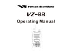
INSTALLATION AND SERVICE
AND PARTS MANUAL FOR
SNORKEL GAS CONVECTION
OVEN MODELS: SG-2, SG-10,
VULCAN-HART CORPORATION, 3600 NORTH POINT BOULEVARD, BALTIMORE, MARYLAND 21222, TEL. (301)284-0660
IMPORTANT
OPERATING, INSTALLING AND SERVICE PERSONNEL
Operating information for this equipment has been prepared for use by qualified and/authorized
operating personnel.
All installation and service on this equipment is to be performed by qualified, certified, licensed and/
authorized installation or service personnel, with the exception of any part marked with a ? in front of
the part number.
Service may be obtained by contacting the Factory Service Department, Factory Representative or
Local Service Agency.
DEFINITIONS
QUALIFIED AND/OR AUTHORIZED OPERATING PERSONNEL
Qualified or authorized operating personnel are those who have carefully read the information in this
manual and are familiar with the equipment's functions or have had previous experience with the
operation of the equipment covered in this manual.
QUALIFIED INSTALLATION PERSONNEL
Qualified installation personnel are individuals, a firm, corporation or company which either in person
or through a representative are engaged in, and are responsible for:
1. The installation of gas piping from the outlet side of the gas meter, or the service regulator when
the meter is not provided, and the connection and installation of the gas appliance. Qualified
installation personnel must be experienced in such work, be familiar with all precautions required,
and have complied with all requirements of state or local authorities having jurisdiction.
Reference in the United States of America - National Fuel Gas Code ANSI Z223.1 (Latest
Edition). In Canada - Canadian Standard CAN/CGA-B149.1 NAT. GAS (Latest Edition) or
CAN/CGA-B-149.2 PROPANE GAS (Latest Edition).
2. The installation of electrical wiring from the electric meter, main control box or service outlet to
the electric appliance. Qualified installation personnel must be experienced in such work, be
familiar with all precautions required, and have complied with all requirements of state or local
authorities having jurisdiction. Reference: In the United States of America - National Electrical
Code ANSI NFPA No. 70 (Latest Edition). In Canada - Canadian Electric Code Part 1 CSA-C22.1
(Latest Edition).
3. The installation of steam piping from the source of supply to the service inlet of the appliance.
Qualified installation personnel must be experienced in such work, be familiar with all precautions
required, and have complied with all requirements of state or local authorities having jurisdiction.
QUALIFIED SERVICE PERSONNEL
Qualified service personnel are those who are familiar with Vulcan equipment who have been
endorsed by the Vulcan-Hart Corporation. All authorized service personnel are required to be
equipped with a complete set of service and parts manuals and stock a minimum amount of parts for
Vulcan equipment.
IMPORTANT NOTES FOR ALL VULCAN APPLIANCES_____________
1. These units are produced with the best possible workmanship and material. Proper installation is vital if best
performance and appearance are to be achieved. Installer must follow the installation instructions carefully.
2. Information on the construction and installation of ventilating hoods may be obtained from the "Standard for the
installation of equipment for the removal of smoke and grease laden vapors from commercial cooking equipment,"
NFPA No. 96 (latest edition) available from the National Fire Protection Association, Battery March Park, Quincy
MA 02269.
3. For an appliance equipped with a flexible electric supply cord, the cord is equipped with a three prong (grounding)
plug. This grounding plug is for your protection against shock hazard and should be plugged directly into a properly
grounded three-prong receptacle. Do not cut or remove the grounding prong from this plug. If the appliance is not
equipped with a grounding plug, and electric supply is needed, ground the appliance by using the ground lug
provided (refer to the wiring diagram).
(FOR GAS APPLIANCES ONLY)
4. Do not obstruct the air flow into and around the appliance. This air flow is necessary for proper combustion of gases
and for ventilation of the appliance. Provisions for ventilation of incoming air supply for the equipment in the room
must be in accordance with National Fuel Gas Code ANSI Z223.1 (latest edition).
5. Do not obstruct the flow of flue gases from the flue duct (when so equipped) located on the rear (or sides) of the
appliance. It is recommended that the flue gases be ventilated to the outside of the building through a ventilation
system installed by qualified personnel.
6. For an appliance equipped with casters, (1) the installation shall be made with a connector that complies with the
Standard for Connectors for Movable Gas Appliances, ANSI Z21.69 (latest edition), and Addenda, Z21.69a (latest
edition), and a quick-disconnect device that complies with the Standard for Quick-Disconnect Devices for Use With
Gas Fuel, ANSI Z21.41 (latest edition), and Addenda, Z21.41a (latest edition) and Z21.41b (latest edition), and (2)
adequate means must be provided to limit the movement of the appliance without depending on the connector and
the quick-disconnect device or its associated piping to limit the appliance movement. If disconnection of the
restraint is necessary, reconnect this restraint after the appliance has been returned to its originally installed
position.
7. The appliance and its individual shutoff valve must be disconnected from the gas supply piping system during any
pressure testing of that system at test pressures in excess of 1/2 psig (3.45 k Pa).
8. The appliance must be isolated from the gas supply system by closing its individual manual shutoff valve during any
pressure testing of the gas supply system at test pressures equal to or less than 1/2 psig (3.45 k Pa).
CAUTIONS
FOR YOUR SAFETY
DO NOT STORE OR USE GASOLINE OR OTHER FLAMMABLE VAPORS AND LIQUIDS
IN THE VICINITY OF THIS EQUIPMENT OR ANY OTHER APPLIANCE.
1. KEEP THE APPLIANCE FREE AND CLEAR FROM ALL COMBUSTIBLE SUBSTANCES.
2. IN THE EVENT A GAS ODOR IS DETECTED, SHUT UNIT(S) DOWN AT THE MAIN
SHUTOFF VALVE AND CONTACT THE LOCAL GAS COMPANY OR GAS SUPPLIER
FOR SERVICE.
3. POST IN A PROMINENT LOCATION, INSTRUCTIONS TO BE FOLLOWED IN THE
EVENT THE SMELL OF GAS IS DETECTED. THIS INFORMATION MAY BE OBTAINED
FROM A LOCAL GAS SUPPLIER.
CAUTIONS (Continued)
CLEARANCE:
FROM THE TERMINATION OF THE APPLIANCE FLUE VENT TO THE FILTERS OF THE HOOD VENTING
SYSTEM, AN 18 INCH MINIMUM CLEARANCE MUST BE MAINTAINED.
REFERENCE: ANSI/NFPA 96-1980 4-1.2.2.2 OF THE NATIONAL FIRE PROTECTION ASSOCIATION, INC.,
BATTERYMARCH PART, QUINCY, MASS. 02269. AND NATIONAL BUILDING CODE 1976 SEC. 1015.7b (2) OF
THE AMERICAN INSURANCE ASSOCIATION, ENGINEERING AND SAFETY SERVICE, 85 JOHN STREET, NEW
YORK, N.Y. 10038.
LOADING:
BEFORE LOADING THE OVEN SET THE LOAD CONTROL DIAL TO THE PROPER SETTING FOR THE
PRODUCT AND THE COOKING LOAD (SEE SEPARATE COOKING CHART).
OPENING OVEN DOORS:
BEFORE OPENING THE OVEN DOORS, PUSH THE AUXILIARY FAN SWITCH TO THE "OFF" POSITION.
OPENING THE OVEN DOORS WILL AUTOMATICALLY CUT "OFF" THE FAN AND THE HEATING ELEMENTS,
BUT IF THE FAN SWITCH IS NOT PUSHED TO THE "OFF" POSITION, HOT AIR GATHERED WITHIN THE OVEN
CAVITY MAY BE PUSHED OUT WHEN THE DOORS ARE OPENED.
CAUTION: DO NOT STAND DIRECTLY IN FRONT OF THE OVEN WHILE OPENING
DOORS.
WHEN OPENING THE DOORS, THE OPERATOR SHOULD PULL THE DOOR HANDLES OPEN WHILE
SIMULTANEOUSLY STEPPING BACK AWAY FROM THE FRONT OF THE UNIT.
LOAD THE OVEN AS QUICKLY AS POSSIBLE TO CONSERVE HEAT. CENTER PANS ON THE RACKS.
HI LIMIT:
THE HI LIMIT IS A PROTECTION DEVICE WHICH SENSES THE TEMPERATURE OF THE UNIT TO PREVENT
APPLIANCE OVERHEATING.
THE HI LIMIT OPERATES INDEPENDENTLY AND WILL AUTOMATICALLY CAUSE UNIT SHUTDOWN SHOULD
THE PRIMARY CONTROL FAIL.
IF THIS SITUATION OCCURS., DO NOT ATTEMPT TO BYPASS THE HI LIMIT. SHUT THE UNIT DOWN AND
CONTACT A SERVICE AGENCY.
2
2A
SNORKEL™ GAS CONVECTION OVEN
INSTALLATION AND SERVICE MANUAL—
Your Vulcan Snorkel gas convection oven is produced
with the best possible workmanship and material. Proper
usage and maintenance will result in many years of
satisfactory performance.
The manufacturer suggests that you thoroughly read this
entire manual and carefully follow all of the instructions
provided.
DESCRIPTION
PAGE
DEFINITIONS OF PERSONNEL (Operation, Installation & Service)
and SHIPPING DAMAGE CLAIM PROCEDURES
CAUTIONS
INDEX
(Inside Front
Cover)
1-2-2A
INDEX
3
GENERAL THEORY OF OPERATION
4
INSTALLATION INSTRUCTIONS
5-6-6A
TROUBLE SHOOTING - SERVICE
7-8
SERVICE REPLACEMENT
COOKING CHART
REPLACEMENT PARTS
REVISION SHEET
Snorkel ranges are supplied with a 7 foot 3 wire supply
cord. Appliances are equipped with a three prong
(grounding) plug for your protection against shock
hazard and should be plugged directly into a properly
grounded three prong receptacle. DO NOT cut or
remove the grounding prong from this plug.
This appliance is to be installed with a six inch
clearance at the sides and rear adjacent to combustible construction.
9-12
13-14
15-15A, 16-16A-24
(Inside Back
Cover)
A rating plate is located on the lower panel stating the
model number, type gas, serial number, voltage and
amperage.
A complete set of wiring diagrams are packed
separately in this unit.
A wiring decal may be found located inside the control
panel compartment.
3
GENERAL THEORY OF OPERATION
GENERAL THEORY OF OPERATION
Figure 1 shows the air distribution and the path of the flue
products in the Vulcan Snorkel oven. There are two
tubular sheet metal burners which operate in an insulated
combustion chamber with minimum air requirements. The
flame chamber collects the heat generated by the burners
and directs it through the heat exchanger tubes which are
within the cooking compartment. The heated flue
products are collected in a box above the oven
compartment and directed to the blower inlet through the
Snorkel tube. The oven compartment is heated indirectly
via the heat exchanger tubes and directly with the flue
products drawn into the oven by the Snorkel tube. A
circulating fan also distributes heat throughout the oven
evenly. The two vents in the top of the oven compartment
evacuate moisture and also vent the oven flue products.
The blower and solenoid operate independently of each
other. The blower operates as long as the doors are
closed or the Aux. Fan Switch is actuated. The solenoid
is controlled by the thermostat and the Load Control. The
thermostat must be On and the Load Control set to an
operating position for the
4
Solenoid to come On and supply heat to the oven. Either
the Thermostat or the Load Control Switch in Off position
will shut off the Solenoid.
In order to provide protection against a pilot outage
hazard, a safety valve controls the main flow of gas to the
burner. As long as a pilot flame is present, the valve will
remain open. In the absence of pilot heat, the valve
closes, eliminating gas to the burner. Each burner has its
own valve which allows them to operate independently of
each other. A snap acting door switch, mechanically
linked with the right hand door, shuts off both the heat
and the blower when the door is opened and will automatically reset when the door is closed.
In ovens equipped with optional Aux. Fan Switch, the
door interlock can be over-ridden by depressing the "Aux.
Fan Switch." The over-ride affects the blower only (not
the heat) and is intended for rapid cooling of the oven
interior.
Under "Component Description and Replacement"
section the detailed function of each component is
explained.
INSTALLATION INSTRUCTIONS
This appliance when installed must be electrically
grounded in accordance with National Electrical Code
ANSI C1-1981.
Vulcan ovens are produced with the best possible
workmanship and material. Proper installation is vital if
best performance and appearance is to be achieved.
Please follow these instructions carefully.
1. Remove crating with care. Remove all wood blocking,
packing material and accessories.
2. Each unit is factory equipped and electrically connected
for use with type of gas and electric supply indicated on
rating plate behind the lower panel. Check type of gas and
electric supply available.
3. Secure oven to stand with two bolts at front (refer
to Detail A).
Position unit as near to final location as possible.
4. Pipe Joint compounds used when connecting appliances to gas should be resistant to the action of
L.P. Gases.
SECTION 1
5. Pipe Joints should be tested for leaks with a soap and
water solution before operating the unit.
6. Connect oven to gas supply through shut-off valve and
gas pressure regulator provided.
Units for use on natural gas are equipped with a regulator
with a preset outlet pressure of 3.7" water column. Units
for use on propane gas have a regulator with a preset
outlet pressure of 10.0" water column. Regulator must be
mounted horizontally to provide the preset outlet pressure.
If regulator is mounted in any other position, the outlet
pressure must be reset.
Note: Do not obstruct leak limiter on gas pressure
regulator.
7. Connect oven to electric supply. 115 volts ovens single
phase units are equipped with a 7 ft. 3 wire (including
ground) supply cord. 115 volt appliances are equipped
with a three prong (grounding) plug for your protection
against shock hazard and should be plugged directly into
a properly grounded three prong receptacle. Do not cut or
remove the grounding prong from this plug. 208/240 volt
units with a single or three phase motor are provided with
a terminal block. 208/240 volt units must be electrically
grounded at time of installation.
8. Install draft diverter if required. Either a draft diverter or
low profile deflector is shipped with every oven. Low
profile deflector is intended for use when oven is installed
under canopy type hoods. When the oven is directly
connected to a vent system, a down draft diverter must be
used.
9. When mobile carriers or basket dollies are to be used,
the standard oven racks and supports are left out. Mobile
carriers or basket dollies are for use in SG-10, SG-10SM,
only.
A. The cart used to transport mobile carriers and
basket dollies has a guide and locking device to
align runners on cart with runners on oven deck.
5
INSTALLATION INSTRUCTIONS (Cont'd)
B. When using 18 x 26 pans with single rack carrier, the
racks are not required. Engage 18 x 26 pan rim on rack
carrier runners.
The oven deck height should now be adjusted to align with
cart height.
pilot burner. If pilot does not light, turn gas off, wait 5
minutes and repeat steps 1 thru 5 of 12A. It is not
necessary to repeat pilot lighting everyday.
For units with electronic ignition, pilot lighting is not
necessary. The main burners are ignited by spark
when thermostat is turned on.
10. Using a carpenter level placed on a rack, adjust the
B. Units with electronic ignition:
feet on the bottom of each leg, so that oven is level from
front to back and side to side. This must be done with
either standard rack supports or optional extra mobile
carriers when used.
No pilot lighting is necessary. Main burners are ignited
by spark when thermostat is turned on.
13. To shut down unit, turn off master switch and turn
off gas at the service valve. To relight repeat step 12A
or 12B.
(NOTE: LEVEL OVEN WHEN IN PERMANENT
POSITON ONLY.)
11. Turn on gas. Purge gas line to remove air. Check for
leaks.
Caution: Use soap solution or similar means (do not check
with open flame).
12A. PILOT LIGHTING INSTRUCTIONS:
Units with Standing Pilots (Ref. to Detail "B").
1. If pilot light is out, turn master switch off, open doors,
then wait 5 minutes before relighting.
2. Light pilot with taper.
3. Turn Master Switch to On position.
4. Set thermostat control knob to desired temperature.
(See Cooking Chart for ref.).
5. Set load control to proper setting. (See Cooking Chart
for ref.)
6. For daily shutdown, turn master switch, thermostat knob,
and load control knob to "Off" position.
7. For seasonal shutdown, extinguish pilot, turn master
switch, thermostat knob and load control knob to "Off"
position.
NOTE: Pilot burner flames are preset at the factory before
shipping approximately 1/2" high. Flame should impinge on
sensing bulb located directly below each
Caution: Fan must rotate clockwise when vi ewed
through the oven door. On three phase motor units,
fan rotation can be reversed by interchanging any two
power supply leads. On single phase units with
incorrect fan rotation, contact factory.
FLUE CONNECTIONS
Good ventilation, which includes flue connections and
room drafts, is just as important for correct oven
operation as adequate gas supply.
Generally speaking, ovens should never be directly
flue connected, if a direct flue system can be avoided.
The ideal method of ventilating a Convection oven is
the use of a properly designed hood. Hood should
extend about 6" beyond all sides of the appliance. The
hood should be connected to an adequate exhaust
duct or system.
When ovens are installed in locations with low ceilings,
care must be taken to insure proper clearance for the
flue products. Lack of this clearance above outlet of
rear flue piping will interfere with heat circulation in the
oven and could create a fire hazard condition. Refer to
NFPA #96.
Do not permit fans to blow directly at the oven and
wherever possible, avoid open windows next to oven
sides or back and wall type fans which create air cross
currents within the room.
It is also necessary that sufficient room air should be
allowed to enter the room to compensate for the
amount of air removed by any ventilating system.
Otherwise, a subnormal atmosphere pressure will
occur, affecting oven operation adversely and causing
undesirable working conditions.
A properly designed and installed hood will act as the
heart of the ventilating system for the room or area in
which the oven is installed, and will leave the oven
independent of changing draft conditions.
6
INSTALLATION INSTRUCTIONS (Cont'd)
RECOMMENDED USE OF CONTROLS IN
DETAIL C
(FOR ROAST AND HOLD OVENS)
1. MOISTURE VENT DAMPER: (NOT SHOWN)
Pull damper knob out to open damper releasing excess
moisture generated while cooking products with high
moisture content. Close damper when dry products are
being cooked. Intermediate adjustments permit
selection for optimum performance.
2. MASTER SWITCH - ITEM 2
Main on-off switch which converts elec. supply to oven
controls.
3. THERMOSTAT SINGLE LIGHT - ITEM 3
Light "On" indicates that oven is preheating or has not
recovered in temperature to the dial setting during
cooking cycle.
4. THERMOSTAT - ITEM 4
The thermostat is a snap-acting on-off type control. The
thermostat regulates the oven temperature from 200°
thru 500°. Turn dial clockwise to increase temperature
and control counter-clockwise to decrease temperature.
NOTE: All heating elements are under supervision of
the thermostat.
5. LOAD CONTROL LIGHT - ITEM 5
Light "On" indicates load control is operating in the
range between the high and low settings.
6. LOAD CONTROL - ITEM 6
An infinite switch which permits variation of the heat
input between off and 100 percent of the input.
DIAL SETTING
HI
HlMED+
MED
MEDLO+
LO
OFF
PERCENT OF FULL INPUT
100%
83%
72%
60%
48%
37%
27%
0%
8. FUNCTION SWITCH - ROCKER SWITCH
ITEM 8
Puts oven in normal or roast & hold mode.
9. ROAST TIMER — 5 HOUR (OPTIONAL 12 HR.)
ITEM 9
Used to set the time interval for the roasting portion of
the roast & hold cycle. When timer times out to "H", the
timer switches the temperature control of the oven from
the adjustable thermostat (main) to the fixed (160°)
thermostat for the holding portion of the cycle.
10. OVEN LAMP SWITCH - (NOT SHOWN)
Rocker switch controls interior oven lights. Turn on
lights only when loading, unloading or checking product.
Continual burning of lights will result in short bulb life.
(Bulb replacement not covered under warranties).
12. AUXILIARY FAN SWITCH - (NOT SHOWN)
7. ONE HOUR TIMER - ITEM 7
Select for any time interval up to one hour. At the end of
selected interval, an electric buzzer will give a
continuous signal. Turn timer to hold position to stop
buzzer or when timer is not in use.
Controls operation of fan when doors are in open
position. This permits rapid cooling of oven. Use when
next load is to be cooked at a much lower temperature
than load just completed.
6A
TROUBLE SHOOTING — SERVICE
The following is intended to provide a guide for trouble
shooting procedure and covers some of the more
common problems with the equipment. The servicing
personnel, as with any other equipment, need to become
If no voltage, the Master Switch is defective.
If 115 volt, check for bad connection from the switch
terminal to the Thermostat and motor connections.
familiar enough with the circuit and the components in
order to be able to follow a logical sequence of trouble-
Step B — Only the door switch can disable the blower
and heat at the same time. While opening and closing the
right hand door listen for a click near the top of the right
shooting, and repair malfunctions not mentioned in the
following paragraphs.
hand door. If no click, the door switch requires
adjustment. If the switch does click but no heat or blower,
The instruments necessary for trouble-shooting would be:
A. A.C. Voltmeter to measure line voltages up to 480 volt.
the switch may be defective.
B. A.C. Amp-meter to measure line currents.
C. Accurate Thermometer to measure oven temperature
Problem: 2. The blower is "ON" (with aux. fan
switch de-energized) but no heat.
up to 500°F.
In the following paragraphs, the voltmeter is used to
measure the voltage between 2 phases on 208, 240, 480
volt and between one phase and neutral on 220/380 and
240/415 volt supplies. Do not measure the voltage with
respect to the chassis ground. For the sake of simplicity,
the measured voltage is referred to 115 volt, assuming
that the supply is 115 volt. When supply is 240 or 220, the
measured voltage should also be 240 or 220—it is also
assumed that the voltage rating of the oven matches
exactly (within the allowable supply tolerance) that of the
field supply. Refer to the appropriate wiring diagram at the
end of this booklet for reference.
With the main power and oven circuit breakers "ON", the
master switch turned to "ON" position and the oven door
closed:
Problem: 1. No blower, no heat
Procedure: Depress the Oven Light switch or turn timer
knob to "0" position. If the lights come On and the Buzzer
sounds, follow step B. If not, follow step A.
Step A—Measure voltage between leads 93 and 94 (The
supply side) of the Master Switch.
If no voltage check connection to Power Supply cord and
verify power at wall socket.
If 115 volt, measure voltage across 21 and 22.
7
Procedure: Turn thermostat knob to about 400°F.
position. If oven signal light is turned "ON," follow step A;
if not, follow step B.
Step A — Oven indicator light is "ON." This is an
indication that the door switch, and the thermostat are
functioning properly. The problem can then be related to
the load control switch or the solenoid.
Turn the load control knob to "HI" position.
Check the voltage between terminals L1 & L2 of the load
control switch.
If no voltage, check for bad connection or faulty lead to
the switch.
If 115 volt, check voltage across H1 & H2 terminals of the
switch.
If no voltage, the switch is defective.
If 115 volt, check for defective solenoid or faulty connection between the load control and the solenoid.
Step B — Oven Indicator Light does not come "On". This
is an indication that the door switch, load control or
thermostat could be defective. (Check for a bad
connection between the master switch and the
thermostat, defective thermostat or bad connection
between the normally open contact of the door switches
and leads going to the solenoids.
TROUBLE SHOOTING—SERVICE (Cont'd)
Problem: 3. The oven heats up properly when
Procedure: The internal thermal protector of the motor
empty, but as soon as the food is put in it, the
is sensing a high temperature which is caused by:
temperature drops and the oven never recovers.
A — Hi current. Check for clockwise rotation of shaft, for
any binding on the shaft or the blower wheel (the wheel
Procedure: Meals containing excessive moisture can
cause the temperature to drop. Also, a cause of
temperature drop is excess load.
should be rotated freely by a hand touch.) If none of the
above, the motor may be defective.
Refer to the Cooking Chart to insure that the load is of the
B—Hi ambient. Check for hot air leakage from inside the
oven to the back through the light or motor housings.
recommended capacity for the oven in use.
Check to see if hot air is blown to the motor from the
adjacent equipment.
Problem: 4. The oven temperature keeps
increasing beyond the setting of the thermostat.
Procedure: If the thermostat indicator light cycles on
and off, check for defective solenoid.
Check for proper ventilation in the area.
208-240 volt units note: Sometimes the over current
affects the circuit breaker (15 amp breaker) before it
does the thermal protector; and the circuit breaker keeps
tripping to the "OFF" position.
If the thermostat light remains "ON" check for defective
thermostat (contacts welding)
Problem: 5. The motor turns off and
automatically comes back "ON" after a few
minutes.
8
SERVICE REPLACEMENT
REPLACEMENT PARTS ORDERING
The following information must accompany a replacement parts order or it cannot be filled.
A. Model and Style or Serial Number.
B. Voltage and Phase.
C. Appliance Finish: Permafinish, Stainless Steel, etc. (If
applicable to part to be replaced.)
This information can be found on the instruction plate on
the unit.
Parts may be ordered from your dealer, service agency,
or the factory.
Orders to the factory should be addressed to: Vulcan-
Hart Corporation, 3600 North Point Boulevard,
Baltimore, MD 21222
Warning: Turn the Main Gas Valve and Power Disconnect Switch to OFF before servicing the equipment.
Reconnect the leads of the replacing components exactly
to the original position and reverse procedure for adding
the new component.
1. SWITCH PANEL
Pushing through the front face of the Switch Panel
until spring clips lock into place.
• Reconnect wires to proper terminals.
B. Replacement of Thermostat
• Remove Rear Body Top.
• Remove the Thermostat Bulb from its (2) retaining clips
located in the right rear corner of oven cavity.
• Push Bulb and Capillary Tube through Grommet in
cavity top.
• Push Bulb and Capillary through hole in Switch Panel
Compartment.
• Remove Silicone tubing from Capillary and save for
reinstallation.
• Disconnect wires from Thermostat. Remove control
knobs and mounting screws. Pull Thermostat off back of
panel.
• When reinstalling Thermostat, reverse procedure listed
above. Do not kink Capillary or place sharp bend in Bulb.
Thermostat Calibration Check
• Use a calibrated potentiometer with a thermocouple
located in the center of the fan guard assembly.
Remove two screws from rear flange of Switch Panel
louvered cover. Push cover back exposing Switch Panel
components.
• Set Thermostat Knob to a mid range temperature.
• Allow adequate time for the temperature to stabilize.
A. Replacing Rocker Switches and Indicator
Lights
• Remove knob from dial shaft B, Detail B.
• Turn screw A clockwise to decrease temperature and
counterclockwise to increase temperature. Note: 1/4 turn
of screw A represents a temperature shift of 35 degrees
F°.
• Remove all wire connections to component. Make a
note of terminal positions.
• Compress spring clips on top and bottom of component
while forcing it out the front of the Switch Panel.
Thermostat Calibration
• Replace component in the original position by
9
SERVICE REPLACEMENT (Cont'd)
C. Load Control. A D.P.S.T. cycling Switch varies,
according to its setting, the percent on-time of the output
as shown below:
To replace, remove the knob and the lock-nut—reinstall
same as Item C.
2. BLOWER MOTOR
The Blower Motor has internal thermal protection, and its
sealed bearings do not require any lubrication. The
Load (Element Contactor or Solenoid)
Valve)
Dial Setting
Percent On-Time
Hi
100
Hi-83
Med+
72
Med
60
Med-48
Lo+
37
Lo
27
Off
0
mounting of the Blower Assembly allows servicing from
inside the oven as follows:
Remove Fan cover.
Loosen set screw on airotor with allen wrench.
Pull airotor forward off of the Motor Shaft with wheel
puller.
Remove the (4) nuts holding the motor mounting plate.
Pull the motor assembly forward and rest on cavity
bottom.
INFINITE LOAD CONTROL SWITCH
The Load Control, as shown schematically, is connected
in series with the thermostat, thus providing variable rate
of temperature rise to reach the thermostat setting, as
well as maintaining at the final set temperature.
Therefore, with load control set at Lo, it will take much
longer to reach a desired temperature than with a setting
of Hi. The cooking chart shows the necessary dial setting
for different food products.
To replace, remove the knob and the lock nut. To
reinstall, make sure the dimples on the face of the switch
fall in the slot of the switch panel in order to prevent it
from rotating.
D. Timer (one or five-hour models). The normally open
and common contacts of the electric timer are connected
together, energizing the timer motor when the knob is set
to the desired position. Once the timer completes its set
interval (at zero mark) the common terminal disconnects
from timer motor (shuts the motor off) and connects with
the buzzer. The buzzer will continue to sound until the
knob is manually turned to 'Hold' position where all
contacts are opened (timer motor and buzzer turned off).
Remove the junction box cover and supply leads.
Rest the motor on its back. Remove the (4) flat head
screws, lockwashers, nuts and spacers used to fasten
the Motor Mounting Plate to the Motor.
To install new motor reverse above procedure.
Caution: The motor is suitable for connection to two
different voltage supplies. Check the connection instruction inside the Motor Junction Box Cover to assure
proper connection for the available voltage supply.
The direction of rotation is clockwise as viewed from
inside the Oven. The 1-phase Motors are internally
designed for C.W. rotation. On 3-phase Motors, interchange any two supply leads to convert C.C.W. to C.W.
rotation.
3. OVEN LIGHTS
The two 50 watt, 115 volt bulbs are connected in series
in the Electric and in parallel in the Gas Convection
Ovens.
10
SERVICE REPLACEMENT (Cont'd)
SHUT-OFF VALVE SERVICE
The gas shut off valve is located at the rear of the unit
and should be used to shut the unit down when service is
required to gas components. This valve should also be
used to turn all gas off to the unit when the unit is being
shut down for an extended period of time.
If the shut off valve requires service this may be
accomplished only by turning off the gas supply upstream
of the valve.
PRESSURE REGULATOR SERVICE
The pressure regulator is located at the rear of the unit
downstream of the shut off valve. If the pressure
regulator requires service, this may be accomplished by
turning off the gas supply upstream of the shut-off valve
and pressure regulator and then removing both of these
parts.
effort to correct problems traced to this component,
remove and clean the leak limiter.
PILOT BURNER ADJUSTMENT
Remove lower panel assembly (spring clip mounted) and
light both pilot burners.
Adjust pilot flame heights to approximately 1/2".
Flame should impinge on flame switch sensing bulbs
located directly above the pilot burner flames. See Detail
B on page 5 for location of pilot. Both pilot valves are
located in the front center of the burner compartment.
AIR ADJUSTMENT
Although main burner air is adjusted before shipment, it
should be checked at the time of installation. Excessive
air will cause flames to lift off a burner when cold or may
cause flash-back during normal cycling of unit,
particularly when propane gas is used.
Blockage of the pressure regulator leak limiter will result
in erratic burner operation and pilot outage.
Insufficient air will cause flames to burn with a yellow tip
and result in carbon accumulation in the flame chamber
and heat exchange tubes.
Note: Prior to replacing a pressure regulator, in an
FOR ALL UNITS MANUFACTURED AFTER OCTOBER 1, 1983
BURNER ORIFICE DATA
MODEL
MAXIMUM INPUT PER BURNER
PRESSURE REG. SETTING
ORIFICE DRILL SIZE
SG.2SM. SG.22, SG.2
30,000
6" W.C.
#38
GAS
NAT.
SG.2SM, SG.22. SG.2
30,000
10.0" W.C.
#1/16
PROPANE
SG.10SM,
35.000
6" W.C.
#35
NAT.
35,000
10.0" W.C.
#53
PROPANE
SG.1010, SG-10
SG-10SM
SG.1010. SG.10
FOR ALL UNITS MANUFACTURED BEFORE OCTOBER 1, 1983
BURNER ORIFICE DATA
MODEL
MAXIMUM INPUT PER BURNER
SG.2SM, SG 22
PRESSURE REG. SETTING
ORIFICE DRILL SIZE
30,000
3.7" W.C.
#36
GAS
NAT.
SG.2SM, SG 22
30,000
10.0" W.C.
#1/16
SG.10SM, SG.1010
35,000
3.7" W.C.
#33
NAT.
PROPANE
SG.10. SG.1010
35.000
10.0" W.C.
#53
PROPANE
REPLACEMENT OF SOLENOID VALVE, REGULATOR, OR SHUTOFF VALVE FOR MODELS SG-2, SG-10
• Turn off gas supply upstream of unit.
• Break gas connection at shut off valve.
• Break compression fittings at front manifold.
• Remove (4) bolts (inside center chamber) to rear
• Disconnect wires to solenoid at wire nuts.
• Pull manifold out back of unit.
• Remount manifold by reversing procedure listed
above.
manifold support.
REPLACEMENT PARTS ORDERING
THE FOLLOWING INFORMATION MUST ACCOMPANY A REPLACEMENT PARTS ORDER OR IT CANNOT BE FILLED.
A. MODEL AND STYLE NUMBER.
B. TYPE OF GAS.
C. APPLIANCE FINISH, BLACK OR STAINLESS STEEL, (IF APPLICABLE TO PART TO BE REPLACED.)
THIS INFORMATION CAN BE FOUND ON THE RATING PLATE LOCATED INSIDE THE LOWER FRONT PANEL OF THE
UNIT
PARTS MAY BE ORDERED FROM YOUR DEALER, SERVICE AGENCY, OR THE FACTORY.
ORDERS TO THE FACTORY SHOULD BE ADDRESSED TO VULCAN.HART CORP., 3600 NORTH POINT BLVD.
BALTIMORE, MD 21222.
12
COOKING CHART
IMPORTANT
Recommended temperatures, times, number of racks and
load control settings are intended as a guide only.
Adjustments must be made to compensate for variations
in recipes, ingredients, installation and personal
preference in product appearance.
RECOMMENDED TEMPERATURES, TIMES
AND LOADS FOR ROASTING
Meat roasting is most satisfactory at temperatures of 225°
to 325° F. for Beef, Lamb, Poultry and Ham; 325° to 350°
for fresh Pork as recommended by USDA and American
Meat Institute.
A pan of water (approximately 12" x 20" x 1") may be
placed in the oven bottom. This water supplies humidity
to reduce shrinkage. Water should be added if necessary
during roasting.
Roasting pans should be no deeper than necessary to
hold drippings, usually 2" to 2 1/2".
Cooking time and shrinkage may vary with roasting
temperature, cut and grade of meat and degree of
doneness. Smaller cuts will generally show greater time
savings than larger cuts at a given temperature.
ROASTING TEMPERATURE CHART
PRODUCT
TEMPERATURE
LOAD CONTROL
SETTING
Standing Rib Roasts—Oven Ready
250° F
HI
Rolled Rib Roasts—20 to 22 Lbs
Veal Roast—15 Lbs
Turkeys—15 to 20 Lbs
Meat Loaf—8 to 10 Lbs
275° F
300° F
300° F
350° F
HI
HI
HI
HI
APPROXIMATE TIMES
3 to 4 Hrs —Rare
4 to 4 1/2 Hrs.—Med.
4 Hrs.—Med.
3 Hrs —Med Well
3 Hrs.
45 to 60 Minutes
RECOMMENDEDTEMPERATURES, TIMES AND LOADS FOR BAKING (ALL SNORKEL MODELS)
PRODUCT
Cakes
Sheet Cakes 18 x 26 x 1"
Scaled 41/2 to 6 Lbs. Per Pan
Scaled 6 to 7 1/2 Lbs Per Pan
TEMPERATURE
TIME IN MINUTES NO. OF RACKS
325° to 360°F
335° to 350°F
20 to 23
22 to 25
5
4
4
Med+ to Med
Med to MedMed to Med-
300° to 325° F
25 to 35
3
Med-
300° to 325° F
15 to 20
4
Lo+
315° to 340° F
350° to 400°
350° to 375° F
20 to 30
6 to 12
30 to 45
Pumpkin or Custard Pies
300° to 350° F
30 to 45
3-4
4
4
3
4
3
Med-to Lo
Med to MedMed to MedMedMed to MedMed- to Lo+
Cobblers
12 x 18 x 2" or 12 x 20 x 2 1/2"
350° to 400° F
30 to 45
Sheet Cakes 18 x 26 x 2" Pan
Equals 2-12 x 18 x 2" Pans
Scaled 10 to 12 Lbs Per 18 x 26 x 2" Pan or
5 to 6 Lbs Per 12 x 18 x 2" Pan
Angel or Sponge Cakes
Sheet Pans 18 x 26 x 1" Scaled
5 to 6 Lbs Per
Loaf or Tube Pans
Cup Cakes
Frozen Fruit Pies
4
3
Meringue Pies
350° to 425° F
6 to 10
4
3
2
Fruit Turnovers
350° to 375° F
15 to 25
5
18 x 26 x 1" Pans
4
3
Cookies
350° to 400° F
6 to 12
5
Rolled or Pressed
4
3
Drop
350° to 400° F
6 to 15
5
4
3
Brownies
350° F
12 to 20
5
4
Rolls—1 Oz
350° to 400° F
5 to 10
4
3
Rolls—11/2 to 2 1/2 Ozs
350° to 400° F
8 to 15
4
3
Loaf Bread—1 Lb
325° to 375°F
20 to 40
3 (30 Pans)
2 (20 Pans)
NOTE: Pies and Cobblers; Fruit, Custard and Pumpkin Pies in tins, should be placed on 18 x 26 x 1" Pans for Baking
LOAD CONTROL
Med
MedMed to MedMed to MedMed to MedMed to MedMed to MedMed-to Lo+
Med to Lo+
Med-to Lo+
Lo+
Med to MedMed-to Lo+
Lo+
Med to MedMed-to Lo+
Med to MedMedMed to MedMed- to Lo+
MedLo*
NOTE: This chart is for models: SG-2SM, SG-22, SG-10SM & SG-1010.
13
COOKING CHART (Cont'd)
RECOMMENDED TEMPERATURES, TIMES AND LOADS FOR BAKING (ALL SNORKEL MODELS)
PRODUCT
Yeast Breads
Note: Yeast Breads should be fully proofed for best results
TEMPERATURE
TIME IN
MINUTES
NO. OF
RACKS
LOAD
CONTROL
4
3
4
3
Med to MedMed- to Lo+
6 to 18
4
3
MedMed- to Lo*
335° to 400° F
10 to 20
4
Med to Med-
8 to 20 Lbs. Per 18 x 26 x 2"
335° to 400° F
15 to 25
4
3
Med to MedMed- to Lo*
Corn Muffins
335° to 385° F
10 to 20
4
3
Med to MedMed to Lo*
Hamburger Patties
8 Per Lb Med Well Done
400° to 450° F
5 to 6
4 to 6
2&3
Hi- to Med*
Med* to Med
6 Per Lb
400° to 450° F
7 to 10
4 to 6
2&3
Hi to HiHi- to Med*
4 Per Lb
375° to 450° F
8 to 12
4 to 6
2&3
Hi
Hi- to Med*
Fish Sticks & Portion—Frozen Breaded 1 Oz
350° to 400°F
6 to 10
4
2&3
Hi- to Med
Med* to Med-
2 1/2 to 3 Ozs
350° to 375° F
8 to 15
4
2&3
Med* to Med
Med to Med-
Chicken Pieces—Broiler or Oven Fried 2 to 2 1/2 Lb Bird
375° to 425°F
8 to 15
4 to 5
2&3
Hi- to Med
Med* to Med-
2 1/2 to 3 Lb Bird
350° to 400° F
15 to 25
4
2&3
Med* to Med
Med to Med-
400° to 450°
8 to 14
2 to 4
Hi to Med
350° to 400° F
10 to 15
2 to 4
Hi- to Med
Frozen French Fries
400° to 450° F
6 to 8
4 2 to 3
Hi- to Med
Med* to Med-
Frozen Lunches (TV Dinners)
350° to 400° F
10 to12
4 to 5
2 to 3
Hi to Med
Med* to Med-
Frozen Entrees (3/4" to 1" Thick)
300° to 350° F
10 to 20
2 to 5
Hi to Med
Frozen Meals (8 Oz ) Foil Pkg
350° to 400° F
20 to 30
2 to 5
Hi
325° to 375° F
325° to 375° F
15 to 25
20 to 35
2 to 4
Med* to Med-
350° to 400° F
5 to 6
4 to 5
2 to 4
Hi to Med*
Med+ to Med
Sweet Rolls & Danish Pastries
325° to 375° F
5 to 15
Quick Breads Biscuits
Rolled 1/2" Thick
350° to 400° F
5 to 15
Muffins
325° to 375° F
Corn Bread
5 to 7 Lbs Per Pan Per 18 x 26 x 1" Pan
Med to Med+
Med- to Lo
OVEN BROILING OR FRYING
Lobsters—1 to 1 1/2" Lb.
Lobster Tails—Frozen 1/2 to 3/4 Lb
REHEATING PREPARED FOODS
CASSEROLES
Food Service Pans
2" to 3" Deep
3"to 4" Deep
Ramikins or Foil Pans
Up to 1 1/2" Deep
*(Frozen 10 to 15 Minutes)
RECOMMENDED TEMPERATURES, TIMES AND LOADS MISCELLANEOUS PRODUCTS
Baked Potatoes
120 Count Per 50 Lbs
100 Count Per 50 Lbs.
80 Count Per 50 Lbs
400° to 450° F
400° to 450° F
400° to 425° F
20 to 25
25 to 40
30 to 50
2 to 5
2 to 5
2 to 5
Hi- to Med
Med+ to Med
Med+ to Med-
Pizzas—Frozen or with Prebaked Crust
425° to 475° F
5 to 10
42&3
Hi- to Med
Med to Med-
Melted Cheese Sandwiches
400° to 425° F
8 to 10
4 2 &3
Hi- to Med
Med+ to Med-
NOTES ON SPECIAL PROCEDURES FOR BAKING
Yeast Bread: Cooking starts immediately in the convection oven. Yeast
Breads do not usually rise as much in the convection oven as in a
conventional oven. It is. therefore, usually necessary to allow fuller
proof. 2 1/2 to 3 times increase in volume for the best results,
Pies: When baking pies in your convection oven. 3 or 4 pies should be
put on an 18 x 26" sheet or bun pan. This procedure helps the bottom
crust to bake. makes handling easier and reduces the possibility of boil
over spoiling the appearance of the pies on the lower racks-
NOTE: This chart is for models: SG-2SM, SG-22, SG-10SM & SG-1010.
14
CONTROL PANEL & COMPARTMENT
120V TOP MOUNT
ITEM
NUMBER
1
2
3
4
5
6
7
8
10
11
12
14
19
DESCRIPTION
ROCKER SWITCH
SIGNAL LIGHT
THERMOSTAT
CONTROL KNOB
INFINITE SWITCH
TIMER 60 MIN.
TIMER 5 HOUR. (OPTIONAL) NS
5 HR. TIMER DECAL (OPTIONAL) NS
RELAY
BUZZER
SNORKEL NAMEPLATE
PORCELAIN BLOCK
MYLAR CONTROL PLATE
NS—NOT SHOWN
15
SG-2
111496-B1
111496-E4
111506-3
111242-1
111503-1
111690-1
111690-3
111693-1
111497-A1
111499-2
113632-1
414881-1
111903-7
QUANTITY
SG-2
3
2
1
3
1
1
1
1
1
1
1
2
1
SG-10
111496-B1
111496-E4
111506-3
111242-1
111503-1
111690-1
111690-3
111693-1
111497-A1
111499-2
113632-1
00081
111903-7
QUANTITY
SG-10
3
2
1
3
1
1
1
1
1
1
1
2
1
CONTROL PANEL & COMPARTMENT
ROAST & HOLD 115V
ITEM NO.
1
2
3
3A
4
5
6
7
10
11
12
13
19A
67
DESCRIPTION
PART NUMBER
SG-2 & SG-10
ROCKER SWITCH
SIGNAL LIGHT
THERMOSTAT
THERMOSTAT
CONTROL KNOB
INFINITE SWITCH
TIMER 60 MINUTE
TIMER 5 HOUR
RELAY
BUZZER
SNORKEL NAMEPLATE (NS)
PORCELAIN BLOCK
MYLAR CONTROL PLATE ROAST & HOLD
GROUND LUG
111496-B2
111496-E4
111506-3
113764-1
111242-1
111503-1
111690-1
111690-3
111497-A1
111499-2
113632-1
00081
113950-4
3.1500/06089
QUANTITY
4
2
1
1
4
1
1
1
3
1
1
1
1
1
NS = NOT SHOWN
15A
CONTROL PANEL & COMPARTMENT
208V & 240V TOP MOUNT
ITEM
NUMBER
DESCRIPTION
1
2
3
4
5
6
7
8
10
11
12
14
16
17
19
67
95
ROCKER SWITCH
SIGNAL LIGHT
THERMOSTAT
CONTROL KNOB
INFINITE SWITCH
TIMER 60 MIN.
TIMER 5 HR. (OPTIONAL) NS
DECAL FOR 5 HR. TIMER NS
RELAY
BUZZER
SNORKEL NAMEPLATE
PORCELAIN BLOCK
TRANSFORMER
TERMINAL BLOCK (3 POLE)
CONTROL PLATE MYLAR
GROUND LUG
BREAKER
NS—NOT SHOWN
16
SG-2
QUANTITY SG-2
SG-10
QUANTITY
SG-10
111496-B1
111496-E4
111506-3
111242-1
111503-1
111690-2
111690-4
111693-1
111497-A1
111499-1
113632-1
00081
111500-6
110472-8
111903-7
3.1500/06089
111501-5
3
2
1
3
1
1
1
1
1
1
1
1
1
1
1
1
2
111496-B1
111496-E4
111506-3
111242-1
111503-1
111690-2
111690-4
111693-1
111497-A1
111499-1
113632-1
00081
111500-6
110472-8
111903-7
3.1500/06089
111501-5
3
2
1
3
1
1
1
1
1
1
1
1
1
1
1
1
2
CONTROL PANEL & COMPARTMENT
240 VOLTS ROAST & HOLD
ITEM
NO.
1
2
3
3A
4
5
6
7
10
11
12
14
16
17
19A
67
95
DESCRIPTION
PART NUMBER
SG-2 & SG-10
ROCKER SWITCH
SIGNAL LIGHT
THERMOSTAT
THERMOSTAT
CONTROL KNOB
INFINITE SWITCH
TIMER 60 MINUTE
TIMER 5 HOUR
RELAY
BUZZER
SNORKEL NAMEPLATE
PORCELAIN BLOCK
TRANSFORMER
TERMINAL BLOCK
CONTROL PANEL MYLAR
GROUND LUG
BREAKER
111496-B2
111496-E4
111506-3
113764-1
111242-1
111503-1
111690-1
111690-3
111497-A1
111499-2
113632-1
00081
111500-6
110472-8
113950-4
3.1500/06089
111501-5
QUANTITY
4
2
1
1
4
1
1
1
3
1
1
1
1
1
1
1
1
16A
OVEN LAMP ASSEMBLY
ITEM
NUMBER
36
37
38
39
40
41
79
DESCRIPTION
SG-2
LAMP SOCKET
LIGHT BULB 155V 50W (FROSTED)
LAMP BOX HOUSING ASSEMBLY
LAMP BOX GASKET NS
LAMP BOX ASSEMBLY
LAMP WINDOW ASSEMBLY
REAR CLOSURE
21201-20
107793-2
111395-G1
111206-1
111394-G1
111175-G1
112827-1
NS—NOT SHOWN
17
QUANTITY SG-2
SG-10
QUANTITY
SG-10
2
2
2
2
2
2
2
21201-20
107793-2
111395-G1
111206-1
111394-G1
111175-G1
112827-1
2
2
2
2
2
2
2
MOTOR
ITEM
NUMBER
62
63
64
65
66
78
DESCRIPTION
MOTOR MOUNT
MOUNTING BOLT
MOTOR SPACER
LOCK NUT
MOTOR 120V OR 208/240 1 PH
Motor 480V 3 PH OR
208/240 3 PH OPTION
LOCKWASHER NS
SG-2
QUANTITY
SG-2
SG-10
QUANTITY
SG-10
112629-1
102085-20
112630-1
104084-9
111205-5
1
4
4
4
1
112629-1
102085-20
112630-1
104084-9
111205-5
1
4
4
4
1
111205-8
3.0201/102524
1
4
111205-8
3.0201/102524
1
4
NS—NOT SHOWN
18
ITEM NO.
42
43
44
45
46
47
48
49
50
50A
52
53
54
55
56
57
58
59
60
60A
61
62
DESCRIPTION
SOLENOID VALVE
DOUBLE PILOT VALVE
ELBOW 1/8M TO 1/4CC
OVEN SAFETY
BURNER NOZZLE
FITTING ELBOW
1/8FM x 1/4CC (NS)
3/4 CLOSE NIPPLE (NS)
SHUT-OFF VALVE (NS)
REGULATOR 3.7 RV43A
(NAT.) (NS)
REGULATOR 10 RV-43
(L.P.) (NS)
7/16CC TEE
COUPLING 3/4 x 3/8
3/8 CLOSED NIPPLE
MAIN GAS SUPPLY
7/16 TUBE (NS)
TUBING SOLENOID TO
ADJ. VALVE
RIGHT PILOT TUBE 3/16
LEFT PILOT TUBE 3/16
LT. & RT. NOZZLE TUBES 7/16
BURNER SPUD (NS)
BURNER SPUD (NS)
BURNER ASSEMBLY
REAR MANIFOLD ASSEMBLY
PART NUMBER
SG-2
QUANTITY
SG-2
PART NUMBER
SG-10
QUANTITY
SG-10
111497-F1
109557-4
13178
114613-1
104079-F
2
1
1
2
2
111497-F1
109557-4
13178
114613-1
104079-F
2
1
1
2
2
114678-2
113500-E11
111420-1
1
1
1
114678-2
113500-E11
111420-1
1
1
1
108279-1
1
108279-1
1
108279-3
114614-1
114782-3
113500-C6
1
1
1
2
108279-3
114614-1
114782-3
113500-C6
1
1
1
2
114624-1
1
114624-1
1
112722-2
114633-2
114633-1
114619-1
10901-36
10901-1/16
112709-G1
111872-G4
1
1
1
2
2
2
2
3
112722-2
114633-2
114633-1
114619-1
10901-33
10901-53
112709-G1
111892-G3
1
1
1
2
2
2
2
3
NS — NOT SHOWN IN PHOTOGRAPH
NOTE: PHOTO SHOWS ALTERNATE HARPER-WYMAN SAFETY CONSTRUCTION.
19
ITEM
NUMBER
97
98
99
52
100
DESCRIPTION
PART
NUMBER
SG-2
QUANTITY
SG-2
PART
NUMBER
SG-10
QUANTITY
SG-10
OVEN SAFETY
LEFT & RIGHT SUPPLY TUBE
MAIN GAS SUPPLY TUBE
TEE 7/16 CC
ELBOW 7/16 CC
114644-1
114635-1
114620-1
114614-1
103638-3
2
2
1
1
1
114644-1
114635-1
114620-1
114614-1
103638-3
2
2
1
1
1
FOR USE WITH ROBERTSHAW SAFETY SYSTEM
20
ITEM
NUMBER
DESCRIPTION
PART
NUMBER
SG-2
QUANTITY
SG-2
PART
NUMBER
SG-10
QUANTITY
SG-10
101
102
103
104
BURNER
OVEN PILOT
LEFT HAND PILOT TUBE
RIGHT HAND PILOT TUBE
114646-1
114645-1
114658-1
114658-2
2
2
1
1
114646-2
114645-1
114658-1
114658-2
2
2
1
1
FOR USE WITH ROBERTSHAW SAFETY SYSTEM
21
ITEM
NUMBER
DESCRIPTION
PART
NUMBER
SG-2
QUANTITY
SG-2
PART
NUMBER
SG-10
QUANTITY
SG-10
101
102
BURNER
OVEN PILOT
114646-1
114645-1
2
2
114646-2
114645-1
2
2
FOR USE WITH ROBERTSHAW SAFETY SYSTEM
22
DOOR ASSEMBLY & MECHANISM
ITEM
NUMBER
81
82
83
84
85
86
87
88
89
90
91
93
94
96
DESCRIPTION
DOOR STRIKE
DOOR CATCH PLATE
COMPRESSION SPRING
MICRO SWITCH
MICRO SWITCH SUPPORT
MICRO SWITCH INSULATION
(3"LONG)NS
DOOR ADJ. BRACKET
HINGE PIN BEARING
COLLAR HINGE PIN 1/2"
DOOR HANDLE ASSEMBLY
DOOR PANEL ASSEMBLY
DOOR WINDOW
PLUG BUTTON NS
DOOR CATCH
NS—NOT SHOWN
23
SG-2
QUANTITY
SG-2
SG-10
QUANTITY
SG-10
111170-1
111934-1
20707-23
111496-F1
110619-1
2
1
2
1
1
111170-1
111923-1
20707-23
111496-F1
110619-1
2
1
2
1
1
111365-1
111939-1
104629-2
3.0209-2
113030-G1
112606-G2
111294-2
3.0317-8
111794-1
2
4
4
1
2
2
2
4
2
111365-1
111939-1
104629-2
3.0209-2
113030-G1
112606-G2
111294-2
3.0317-8
111794-1
2
4
4
1
2
2
2
4
2
OVEN CAVITY
ITEM
NUMBER
19
19A
21
22
23
24
26
26A
27
28
29
30
31
32
33
34
35
DESCRIPTION
FAN COVER ASSEMBLY
FAN COVER ASSEMBLY (SS)
OVEN RACK
RIGHT HAND RACK SUPPORT
LEFT HAND RACK SUPPORT
DRIP TRAY GUIDE NS
DRIP TRAY NS
DRIP TRAY SS NS
RIGHT HAND SIDE LINING
LEFT HAND SIDE LINING
RIGHT HAND SIDE LINING SS
LEFT HAND SIDE LINING SS
DOOR GASKET
TOP & BOTTOM DOOR GASKET
SHIM NS
SIDE DOOR GASKET SHIM NS
AIROTOR 10"
SNORKEL TUBE ASSEMBLY
SG-2
QUANTITY
SG-2
SG-10
QUANTITY
SG-10
111136-G2
111136-G4
111265-2
111430-2
111430-1
112845-1
111429-1
111429-2
112697-1
112697-2
112697-3
112697-4
111688-1
1
1
6
1
1
2
1
1
1
1
1
1
1
111136-G2
111136-G4
111265-1
111430-3
111430-4
112845-2
111429-3
111429-4
112697-5
112697-6
112697-1
112697-8
111688-1
1
1
6
1
1
2
1
1
1
1
1
1
1
111339-1
111339-2
3.1300-3
114296-G1
2
2
1
1
111339-1
111339-2
3.1300-3
113585-G1
2
2
1
1
NS—NOT SHOWN
24