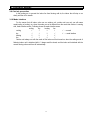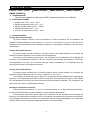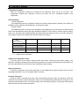
1
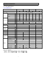
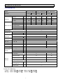
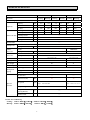
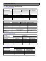
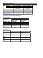
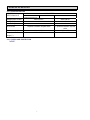
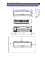
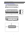
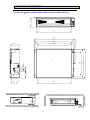
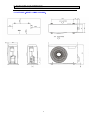
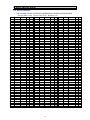
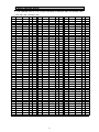
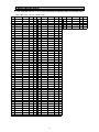
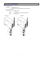
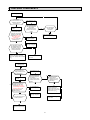
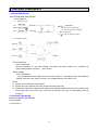
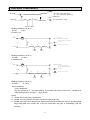
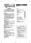
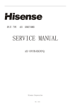
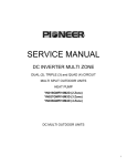
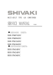
MULTI-SPLIT TYPE AIR CONDITONER
SERVICE MANUAL
●INDOOR
UNIT:
AMS-07UR4SNZA3
AMS-09UR4SNZA3
AMS-12UR4SNZA3
AMS-18UR4SPZA3
AMD-09UX4SJC
AMD-12UX4SJC
AMD-18UX4SJC
●OUTDOOR
AMW2-16U4SGC
AMW2-20U4SNC
AMW3-24U4SKC
AMW4-28U4SKC
UNIT:
Hisense Corporation
V: 3.0
Table of contents
Page
1.OPERATING RANGE
1
2.SPECIFICATION
2
2-1 Unit specifications
2
2-2 Major component specifications
5
2-3 Other component specifications
6
3.OUTLINES AND DIMENSIONS
8
3-1 INDOOR
8
3-2 OUTDOOR
12
4.REFRIGERANT FLOW DIAGRAM
14
4-1 Refrigerant flow diagram
14
4-2 Evacuation procedures
16
4-3 Evacuation direction
17
5.ELECTRICAL DATA
18
5-1 Electric wiring diagrams
18
5-2 Electric control
19
5-3 Sensor parameter
30
6.CONTROL MODE
31
6-1 Indoor control mode
31
6-2 Outdoor control mode
34
7.TROUBLESHOOTING
38
7-1 Error codes
39
8.CHECKING COMPONENTS
40
8-1 Check refrigerant system
40
8-2 Check parts unit
42
9.PARTS LIST
46
9-1 Indoor
46
9-2 Outdoor
51
1. OPERATING RANGE
COOLING
HEATING
Temperature
Indoor Air Intake Temp.
Outdoor Air Intake Temp
Maximum
32℃ D.B./23℃ W.B.
43 ℃ D.B./26℃ W.B.
Minimum
21℃ D.B./15℃ W.B.
21 ℃ D.B./15℃ W.B.
Maximum
27℃ D.B./18℃ W.B.
24℃ D.B./18℃ W.B.
Minimum
20℃ D.B/≤15℃ W.B
-7℃ D.B./-8℃ W.B.
1
2. SPECIFICATIONS
2-1. Unit specifications
2-1-1.OUTDOOR UNIT
Model
AMW4-28U4SKC
Function
Power
Cooling
Heating
AMW3-24U4SKC
Cooling
supply
Heating
a.c
AMW2-16U4SGC
Cooling
Cooling
Heating
Heating
220V~240V/50Hz
Capacity
kW
8.2
9.0
7.0
8.0
5.8
6.4
4.6
5.3
Dehumidification
l /h
----
----
----
----
----
----
----
----
----
----
----
----
----
----
----
----
Capacity
3
m/
Air flow
h
Rated current
A
10.7
11.1
9.7
10.1
7.7
8.0
6.1
5.7
Rated input
kW
2.4
2.49
2.18
2.21
1.7
1.75
1.4
1.3
Electrical data Auxiliary heater
A
------
Power factor
%
99.9%
99.9%
99.9%
99.9%
Max. current
A
15.0
15.0
14.5
14.5
ATL165SD-C9AU
DA130S1C-20FZ
DA130S1C-20FZ
0.590 (at75℃)
0.95(20℃)
0.95(20℃)
YDK70-6H-3
YDK55-6I-8
YDK29-6I-22
SEER/HSPF
Compressor
AMW2-20U4SNC
---Model
Ω
Winding resistance
Outdoor
Model
fan motor
Winding resistance (at20℃)
Ω
M:78;A:80
M:185;A:200
M:283.5;A:180
Net size
L×W×H
cm
109×41×84
98×35×64
80×26×57
Package size
L×W×H
cm
112×46×98
108×42×72
94×36×64
Net weight
kg
67
66
46.2
37.5
Gross weight
kg
77
72
52.5
41
Liquid pipe
mm
6.35×4
6.35×3
6.35×2
6.35×2
Gas pipe
mm
9.52×4
9.52×3
9.52×2
9.52×2
Flare
Flare
Refrigerant
piping
Connection method
Flare
Air direction
Special
remarks
----
----
----
----
Sound level (Hi)
dB
57
57
56
Fan speed (Hi)
rpm
840
840
900
3
3
1.4
1.0
EEV
EEV
Fan speed regulator
Refrigerant
capacity(R410a)
filling
3
kg
Throttle mode
NOTE :Test conditions:
Cooling : Indoor: DB27℃/ WB19℃
Heating: Indoor: DB20℃/ WB15℃
2.1
2.4
EEV
EEV
Outdoor: DB35℃/ WB24℃
Outdoor: DB7℃/ WB 6℃
2
2. SPECIFICATIONS
2-1-2.INDOOR UNIT
AMS-07UR4SNZA3
AMS-12UR4SNZA3 AMS-18R4SPZA3
AMS-09UR4SNZA3
Cooling Heating Cooling Heating Cooling Heating
Model
Function
Power
supply
Capacity
a.c
220V~240V/50Hz
Capacity
kW
2.6
3.0
3.2
3.8
4.8
5.5
Dehumidification
l /h
1.1
----
1.4
----
1.5
----
m3/h
420
520
450
560
700
800
A
0.18
0.18
0.18
0.18
0.2
0.18
kW
40
40
40
40
45
40
Air flow
Running current
Rated input
Electrical data Auxiliary heater
A
----
Power factor
%
----
Starting current
A
----
SEER/HSPF
Compressor
---Model
----
Winding resistance (at25℃) Ω
----
Indoor
fan motor
Model
YYW16-4-532
YYW28-4-2085B
Winding resistance (at20℃) Ω
M:364;A:400.5;
M:246.2;A:191;
Outdoor
fan motor
Model
----
Winding resistance (at20℃) Ω
----
Net size
L×W×H
cm
75×25×19
Package size
L×W×H
cm
84×31×27
96×40×34
Net weight
kg
8.0
12.0
Gross weight
kg
9.5
14.0
Refrigerant
piping
Liquid pipe
mm
6.35
Gas pipe
mm
9.52
Connection method
----
Air direction
Special
remarks
87×23×31
6
6
Sound level (Hi)
dB
37
49
Fan speed (Hi)
rpm
1200
1300
3
3
Fan speed regulator
Refrigerant
filling
capacity(R410a)
kg
----
Throttle mode
NOTE :Test conditions:
Cooling : Indoor: DB27℃/ WB19℃
Heating: Indoor: DB20℃/ WB15℃
----
Outdoor: DB35℃/ WB24℃
Outdoor: DB7℃/ WB 6℃
3
2. SPECIFICATIONS
Model
AMD-09UX4SJC
AMD-12UX4SJC
AMD-18UX4SJC
Function
Cooling
Cooling
Cooling
Power
Heating
supply
Capacity
a.c
Heating
220V~240V/50Hz
Capacity
kW
2.6
3.0
3.2
3.7
5.0
5.5
Dehumidification
l /h
1.5
----
1.5
----
1.9
----
m3/h
440
520
440
520
600
700
A
0.2
0.2
0.2
0.2
0.3
0.3
kW
44
44
44
44
66
66
Air flow
Running current
Rated input
Electrical data Auxiliary heater
A
----
Power factor
%
----
Starting current
A
----
SEER/HSPF
Compressor
Heating
---Model
----
Winding resistance (at25℃) Ω
---YSK25-4G
YSK40-4E
M:247;A:150
M:247;A:150
Indoor
fan motor
Model
Outdoor
fan motor
Model
----
Winding resistance (at20℃) Ω
----
Net size
L×W×H
mm
770×600×190
770×600×190
Package size
L×W×H
mm
946×692×236
946×692×236
Net weight
kg
20
21
Gross weight
kg
24
25
Refrigerant
piping
Winding resistance (at20℃) Ω
Liquid pipe
mm
6.35
Gas pipe
mm
9.52
Connection method
----
Air direction
Special
remarks
Sound level (Hi)
dB
Fan speed
rpm
Fan speed regulator
Refrigerant
filling
capacity(R410a)
----
----
35
37
10pa:980/850/700
10pa:1290/1150/1010
30pa:1150/1070/940
30pa:1400/1310/1150
6
kg
----
Throttle mode
NOTE :Test conditions:
Cooling : Indoor: DB27℃/ WB19℃
Heating: Indoor: DB20℃/ WB15℃
6
----
Outdoor: DB35℃/ WB24℃
Outdoor: DB7℃/ WB 6℃
4
2. SPECIFICATIONS
2-2. Major component specifications
2-2-1.INDOOR FAN MOTOR
ELECTRIC
PERFORMANCE
Motor model
PARAMETER
AMS-07UR4SNZA3
AMS-12UR4SNZA3
AMS-09UR4SNZA3
YYW16-4-532
Rated power source
220V
50Hz
AMS-18R4SPZA3
YYW28-4-2085B
220V
Phases/Poles
1/4
1/4
Rated load output(W)
16
28
Rated speed(r/min)
--
1250
-5℃~+43℃.
Ambient
temperature(℃)
ELECTRIC
PERFORMANCE
50Hz
-5℃~+43℃
PARAMETER
AMD-09UX4SJC
Motor model
AMD-12UX4SJC
YSK25-4G
Rated power source
220V
AMD-18UX4SJC
YSK40-4E
50Hz
220V
Phases/Poles
1/4
1/4
Rated load output(W)
25
44
Rated speed(r/min)
1150/1070/940(Red)
980/850/700(White)
1400/1310/1150(Red)
1290/1150/1010(White)
-5℃~+43℃.
Ambient
temperature(℃)
50Hz
-5℃~+43℃
2-2-2 OUTDOOR FAN MOTOR
ELECTRIC
PERFORMANCE
Motor model
Rated power source
PARAMETER
AMW3-24U4SKC
AMW4-28U4SKC
YDK70-6H-3
220V
50Hz
AMW2-20U4SNC
AMW2-16U4SGC
YDK55-6I-8
YDK29-6I-22
220V
220V
50Hz
50Hz
Phases /Poles
1/6
1/6
1/6
Rated load output(W)
65
47
28
-5℃~+43℃
-5℃~+43℃
Ambient
temperature(℃)
-5℃~+43℃
2-2-3. COMPRESSOR
ELECTRIC
PERFORMANCE
Compressor model
PARAMETER
AMW3-24U4SKC
AMW2-20U4SNC
AMW4-28U4SKC
AMW2-16U4SGC
ATL165SD-C9AU
DA130S1C-20FZ
Compressor type
Rotary
Rotary
Rated power
1550W
990W
10.7
4.97
Current (A)
5
2. SPECIFICATIONS
Motor
Motor type
DC brushless motor
DC brushless motor
DC Inverter
DC Inverter
0.59/0.59/0.59Ω(at 75℃)
U-V/V-W/W-U
0.95/0.95/0.95Ω(at 20℃)
U-V/V-W/W-U
2
2
α68HES-H or equivalent
ESTER OIL VG74
880
500
-5℃~+43℃.
-5℃~+43℃
Starting type
Winding resistance
Number of cylinder
Oil type
Oil charge (cc)
Ambient temperature(℃)
2-3. Other component specifications
2-3-1. INDUCTANCE
ELECTRIC
PERFORMANCE
Inductance model
PARAMETER
AMW3-24U4SKC
AMW2-20U4SNC
AMW4-28U4SKC
AMW2-16U4SGC
R2550HSA
R2050HSB
Rated power source
220V
Rated current(A)
25
20
Rated inductance
5.0(mH)±10%
5.2(mH)±10%
Ambient
temperature(℃)
-20℃~+70℃.
-20℃~+70℃.
50Hz
220V
50Hz
2-3-2. FILTER
ELECTRIC
PERFORMANCE
Filter model
RTNF-250T10X-3LF
AMW2-20U4SNC
AMW2-16U4SGC
RTNF250-25T068X-03LF
Rated current(A)
20
20
Rated
source
power
AC 220V—50Hz
AC 220V—50Hz
frequency
150K—30MHHz
150K—30MHHz
-25℃~+85℃.
-25℃~+85℃.
Filter
range
Temperature
range(℃)
AMW3-24U4SKC
AMW4-28U4SKC
6
2. SPECIFICATIONS
2-3-4. STEPPER MOTOR
ELECTRIC
PERFORMANCE
Stepper Motor model
PARAMETER
AMS-07UR4SNZA3
AMS-12UR4SNZA3 AMS-18UR4SPZA3
AMS-09UR4SNZA3
24BYJ48-CP
24BYJ48-B1
Voltage(DC)
12V
12V
4
4
1-2phase excitation unipolar drive
1-2phase excitation unipolar
drive
300Ω±7%
300Ω±7%
-10℃~+40℃
-10℃~+40℃
Number of phase
Drive mode
Resistance per phase
Temperature
range(℃)
2-3-5. OVERLOAD PROTECTION
NONE.
7
3. OUTLINES AND DIMENSIO
3-1. INDOOR(MODEL: AMS-07UR4SNZA3、AMS-09UR4SNZA3、AMS-12UR4SNZA3)
190mm
250mm
750mm
65mm
94mm
23mm
50mm
631mm
50mm
50mm
8
3. OUTLINES AND DIMENSIO
271
3-2. INDOOR(MODEL: AMS-18UR4SPZA3)
779
50mm
195
50mm
50mm
9
3. OUTLINES AND DIMENSIO
190
3-3. INDOOR(MODEL: AMD-09UX4SJC/AMD-12UX4SJC/AMD-18UX4SJC)
740
808
780
740
688
145.5
47
57
508
595
630.2
168.4
140
122
676
10
3. OUTLINES AND DIMENSIO
3-3.OUTDOOR(MODEL: AMW2-16U4SGC)
11
3. OUTLINES AND DIMENSIO
3-4.OUTDOOR(MODEL: AMW2-20U4SNC)
12
3. OUTLINES AND DIMENSIO
3-5.OUTDOOR(MODEL: AMW3-24U4SKC、AMW4-28U4SKC)
13
4. REFRIGERANT FLOW DIAGRAM
4-1.
Refrigerant flow diagram :
MODEL:AMW3-24U4SKC、AMW4-28U4SKC
A机
B机
C机
D机
D机
C机
B机
Filter
A机
Remark:
The part is only for AMW4-28U4SKC
COOLING CYCLE
HEATING CYCLE
14
4. REFRIGERANT FLOW DIAGRAM
MODEL:AMW2-20U4SNC
AMW2-16U4SGC
4-way valve
A机
B机
B机
EEV B Filter
A机
EEV A Filter
15
4. REFRIGERANT FLOW DIAGRAM
4-2.
Evacuation procedures:
EVACUATION PROCEDURES
Connect the refrigerant pipes (both the liquid and
gas pipes) between the indoor and the outdoor units.
Remove service port cap of the stop valve A and connect gage manifold valve and vacuum
pump to it.
Run the vacuum pump for more than 15 minutes and at this time confirm that the pressure
gage indicates -0.1Mpa(-76 cmHg).
Stop pump and keep the pressure for one or two minutes. Make sure the pressure is no
change(if the pressure is changed to high, there is some leakage for the pipe connection).
Remove gage manifold valve quickly from the service port of the stop valve A.
full open the stop valves A on gas and liquid pipe sides.
Repeat the steps above for other valves(B\C\D), be sure all refrigerant pipes are
connected and evacuated, and all valves are full opend.
Total pipe length is in the range:
No gas charge is needed
Total pipe length exceeding the limit:
Charge the prescribed amount of gas.
Tighten the cap to the service port to obtain the initial status.
Retighten the cap.
Leak test
16
4. REFRIGERANT FLOW DIAGRAM
4-3.
Evacuation direction:
MAX. Refrigerant pipe length and height difference:
AMW3-24U4SKC
AMW2-20U4SNC
AMW4-28U4SKC
AMW2-16U4SGC
Pipe length per. Indoor unit(a/b/c/d)
25m
20m
Total pipe length for multi-system (a+b+c+d)
60m
40m
Height difference (I.D ~ O.D)
15m
15m
Height difference (I.D ~ I.D)
7.5m
7.5m
Modle
*Do your best to reduce the pipe length. Long pipe may cause capacity of the indoor unit incline.
Outdoor unit precharged
Total refrigerant pipe length
0m~20m
AMW3-24U4SKC
2100g
0g
AMW4-28U4SKC
2400g
0g
Outdoor unit precharged
AMW2-20U4SNC
1400g
AMW2-16U4SGC
1300g
20m~60m
Xg = 15g / m × (Total pipe length(m) - 20)
Total refrigerant pipe length
0m~15m
15m~40m
0
Xg = 15g / m × (Total pipe length(m) - 15)
17
5. ELECTRICAL DATA
5-1.Electrical wiring diagrams
INDOOR:
1)AMS-07UR4SNZA3、AMS-09UR4SNZA3、AMS-12UR4SNZA3
2)AMS-18UR4SPZA3
1338610
18
5. ELECTRICAL DATA
2)AMD-09UX4SJC、AMD-12UX4SJC、AMD-18UX4SJC
ELECTRIC WIRING DIAGRAM
FAN CAP
TERMINAL PANEL
TO
OUTDOOR
UNIT
CN18(FAN_N)
1(L)
BROWN
CN01(L_IN)
2(N)
BLU
CN02(N_IN)
RED
CN03(SI)
BLU
WHT
3
(FAN_MOTO)
4(SI)
30Pa
FAN
MOTOR
RED
YLW/GRN
ACFN
10Pa
CN10(FAN_MOTO) WHT
TRANSFORMER
CN08(TRANCE)
YLW/GRN
CONTROL
BOARD
CN09(TRANCE)
HEAT
CN04(HEAT_L)
CN05(HEAT_N)
TEMPERATURE
SENSOR
DISPLAY
PANEL
CN11(FAN_PRO)
GRAY
CN13(FLAP)
STEP
MOTOR
CN14(FLAP)
STEP
MOTOR
CN15(FLAP)
STEP
MOTOR
CN16(FLAP)
STEP
MOTOR
CN17
CN23(DISPLAY)
CN12(PUMP)
CN24
CN21(LEVER SWITCH)
19
PUMP
WATER
INSPECT
5. ELECTRICAL DATA
OUTDOOR:
1)AMW4-28U4SKC
POWER
TERMINAL
PANEL
BLK
1(L)
ELECTRIC WIRING DIAGRAM 1354457.A
BLK
FUSE
FILTER
2(N)
COMPRESSOR
BLU
CM
)
4-WAY VALVE FAN MOTOR
YLW/GRN
AUXILIARY HEATER
FM
VA
CONNECTION
TERMINAL
PANEL D
WHT BLK
1(L)
RED WHT BLU
CAPACITOR
BRN
1 2
1 2
CN6 VA
BLK
BLU
2(N)
4(SI)
1 2 3 4
1 2 3 4
CN7 FM WHT
CN100 CN101 CN102
U
V
W
RED
WHT BLU
CN9 CN10
CN5
BLU
BRN
CONNECTION
YLW/GRN TERMINAL
POWER FILTER BOARD
CN3
PANEL C
CN8 WHT
1 2 3 4 5 6 7 8 9 10
1 2 3 4 5 6 7 8 9 10
CN2
1(L)
YLW/GRN
T1 T2 T3
2(N)
CN4
BRN
CN200 LIN
CN1
BLU
CN201 NIN
PRESSURE
BLU
T1 T2 T3
T1 T2 T3
ELECTROLYTIC
CAPACITOR
T04
1
1
T05
1
1
2(N)
T03
1
1
1(L)
T02
1
1
SI-D
WHT
SI-C ORG
SI-B
BLK
SI-A
RED
SI-N
BLU
1
1
BLU
BRN
CONNECTION
TERMINAL
PANEL B
T01
1 2
1 2
1 2
1 2
1 2
1 2
T-DISS T-GasD T-LiqD
CN201 CN205 CN206
WHT
YEL
RED
1 2
1 2
T-DEF
CN207
BLK
1 2 3 4 5 6
1 2 3 4 5 6
T-Gas-A -B -C
CN204 BLU
1 2 3 4 5 6
1 2 3 4 5 6
T-Liq-A -B -C
CN203 GRN
1 2 3 4 5 6
1 2 3 4 5 6
T-COIL T-SUC T-OUT
CN202 YEL
1 2 3 4 5 6 7 8 9 10
1 2 3 4 5 6 7 8 9 10
CN301 WHT
1 2
1 2
CN101
WHT
2 1
2 1
CN804
RED
INDUCTOR
YLW/GRN
CONTROL BOARD
CN208
CN404 A-EV RED
1 2 3 4 5 6
1 2 3 4 5 6
4(SI)
CN403 B-EV WHT
1 2 3 4 5 6
1 2 3 4 5 6
CN401 D-EV BLU
1 2 3 4 5 6
1 2 3 4 5 6
CN402 C-EV BLK
1 2 3 4 5 6
1 2 3 4 5 6
CN801 WHT
1 2 3 4 5
1 2 3 4 5
CN104 N
BLU
+
CN103 P
RED
RED
BRN
4(SI)
IPM BOARD
3(
CN204
YLW
CN202 L1
CN203 L2
ORG
CN302 WHT CN301 WHT
3 2 1
5 4 3 2 1
3 2 1
5 4 3 2 1
CN105 WHT
1 2 3
1 2 3
YLW/GRN
BLU
BRN
CONNECTION
TERMINAL
PANEL A
OVERLOAD
PROTECTOR
1(L)
2(N)
ELECTRONIC
EXPANSION VALVE A
4(SI)
ELECTRONIC
ELECTRONIC
ELECTRONIC
EXPANSION VALVE B EXPANSION VALVE C EXPANSION VALVE D
YLW/GRN
2)AMW3-24U4SKC:
ELECTRIC WIRING DIAGRAM 1354463.A
POWER
TERMINAL
PANEL
BLK
FUSE
BLK
FILTER
2(N)
COMPRESSOR
BLU
CM
)
4-WAY VALVE FAN MOTOR
YLW/GRN
AUXILIARY HEATER
WHT BLK
1(L)
BRN
2(N)
BLU
1 2
1 2
CN6 VA
BLK
1 2 3 4
1 2 3 4
CN7 FM WHT
CN100 CN101 CN102
U
V
W
RED
WHT BLU
CN9 CN10
CN5
BLU
BRN
CONNECTION
RED WHT BLU
CAPACITOR
4(SI)
YLW/GRN TERMINAL
FM
VA
CONNECTION
TERMINAL
PANEL C
POWER FILTER BOARD
CN3
PANEL B
CN8 WHT
1 2 3 4 5 6 7 8 9 10
1 2 3 4 5 6 7 8 9 10
CN2
1(L)
YLW/GRN
T1 T2 T3
2(N)
T1 T2 T3
CN4
BRN
CN200 LIN
CN1
BLU
CN201 NIN
PRESSURE
BLU
T1 T2 T3
ELECTROLYTIC
CAPACITOR
1 2
1 2
T-DISS
CN201
YEL
BLU
T03
1
1
T04
1
1
T05
1
1
SI-C ORG
SI-B
BLK
SI-A
RED
SI-N
BLU
1
1
2(N)
BRN
1(L)
RED
RED
BRN
4(SI)
YLW/GRN
CONNECTION
TERMINAL
PANEL A
BLU
+
T01
1 2
1 2
T-DEF
CN207
BLK
1 2 3 4 5 6
1 2 3 4 5 6
T-Gas-A -B -C
CN204 BLU
1 2 3 4 5 6
1 2 3 4 5 6
T-Liq-A -B -C
CN203 GRN
1 2 3 4 5 6
1 2 3 4 5 6
T-COIL T-SUC T-OUT
CN202 YEL
1 2 3 4 5 6 7 8 9 10
1 2 3 4 5 6 7 8 9 10
CN301 WHT
2 1
2 1
CN804
RED
1 2
1 2
CN101
WHT
CONTROL BOARD
CN208
CN404 A-EV RED
1 2 3 4 5 6
1 2 3 4 5 6
4(SI)
CN403 B-EV WHT
1 2 3 4 5 6
1 2 3 4 5 6
CN402 C-EV BLK
1 2 3 4 5 6
1 2 3 4 5 6
YLW/GRN
CONNECTION
TERMINAL
PANEL A
OVERLOAD
PROTECTOR
ELECTRONIC
EXPANSION VALVE A
ELECTRONIC
ELECTRONIC
EXPANSION VALVE B EXPANSION VALVE C
20
CN801 WHT
1 2 3 4 5
1 2 3 4 5
CN105 WHT
1 2 3
1 2 3
INDUCTOR
3(
YLW
ORG
CN104 N
CN103 P
CN204
IPM BOARD
1(L)
CN202 L1
CN203 L2
CN302 WHT CN301 WHT
3 2 1
5 4 3 2 1
3 2 1
5 4 3 2 1
5. ELECTRICAL DATA
3)AMW2-20U4SNC:
4)AMW2-16U4SGC:
21
5. ELECTRICAL DATA
5-2. Electric control
1. Control board for indoor unit
1) AMS-07UR4SNZA3、AMS-09UR4SNZA3、AMS-12UR4SNZA3
22
5. ELECTRICAL DATA
2)AMS-18UR4SPZA3
5V
GND
12V
FAN SPEED
FEEDBACK
ROOM COIL
ON/OFF TO DISPLAY
SENSOR SENSOR BUTTON BOARD
FAN MOTOR
DRVING
Step Motor
Drving
ac 220V Nin
ac 220V Lin
Communication
Signal
23
5. ELECTRICAL DATA
3) AMD-09UX4SJC、AMD-12UX4SJC、AMD-18UX4SJC
24
5. ELECTRICAL DATA
2. Control board for outdoor unit(AMW3-24U4SKC、AMW4-28U4SKC)
1)FILTER BOARD
3.15 /250
2)CONTROL BOARD
DC DC in
DC +
To IPM
IPM
POWER Board
To Filter
Board
Communication
Signal D
Communication
Signal N
Communication
Signal C
Communication
Signal B
Communication
Signal A
Overload
Protection
D Valve
Drving
C Valve B Valve
Drving Drving
A Valve
Drving
Gas
Outdoor/ Liquid
Defrose
Suction/ Pipe A/B/C A/B/C
Sensor
Liquid Pipe
Sensor
Condensor Sensor
D Sensor
Sensor
Compressor Discharge Sensor
Gas D Sensor
High Pressure Protection
25
5. ELECTRICAL DATA
3)IPM Board
To PFC
Inductor-1
To PFC
Inductor-2
To Electrolytic
Capacitor +
ac L in
ac N in
To Electrolytic
Capacitor IPM Power
To Compressor W
To Compressor V
To Compressor U
To Electrolytic
Capacitor +
To Main Control
Board
5V
GND
15V
26
5. ELECTRICAL DATA
3. Control board for outdoor unit(AMW2-16U4SGC
1)IPM Board
AMW2-20U4SNC)
To Electrolytic
Capacitor +
To PFC Inductor-2
ac L in
To PFC Inductor-1
To Electrolytic
Capacitor ac N in
IPM Power
To Compressor W
To Compressor V
To Compressor U
To Main Control
Board
To Electrolytic
Capacitor +
2)CONTROL BOARD
Fan Motor Drving
ac N out
ac L out
ac N in
Earth Wire
ac L in
4-Way Valve
Drving
To IPM Board
(Communication)
To IPM Board
(Power)
Overload
Protection
DCDC+
B VALVE
DRVING
27
Outdoor/Suction/
Condensor Sensor
Gas B Sensor
Compressor
Discharge Sensor
Liquid A/B &
B VALVE DRVING
Gas A Sensor
5. ELECTRICAL DATA
5-3. Sensor parameter
1. THE PARAMETER OF OUTDOOR COMPRESSOR TEMPERATURE SENSOR:
(R0=187.25K±6.3%;R100=3.77K±2.5K;B=3979±1%)
T(℃ ) R(KΩ )
-30
966.1
-29
910.3
-28
858
-27
809
-26
763.1
-25
720
-24
679.6
-23
641.7
-22
606.1
-21
572.7
-20
541.3
-19
511.7
-18
484
-17
457.9
-16
433.3
-15
410.2
-14
388.5
-13
368
-12
348.7
-11
330.5
-10
313.4
-9
297.2
-8
281.9
-7
267.5
-6
253.9
-5
241.1
-4
229
-3
217.6
-2
206.8
-1
196.6
0
186.9
1
177.8
2
169.2
3
161
4
153.3
5
146
6
139
7
132.5
8
126.3
9
120.4
10
114.8
11
109.5
12
104.4
13
99.66
14
95.13
15
90.82
16
86.74
17
82.85
18
79.16
19
75.65
20
72.32
21
69.15
22
66.13
23
63.27
24
60.54
25
57.94
V(v)
0.1014
0.1075
0.1139
0.1206
0.1277
0.1351
0.1429
0.1511
0.1597
0.1687
0.1782
0.1881
0.1984
0.2092
0.2206
0.2325
0.2448
0.2577
0.2712
0.2853
0.2999
0.3153
0.3312
0.3478
0.3651
0.3830
0.4016
0.4209
0.4409
0.4617
0.4833
0.5056
0.5285
0.5525
0.5770
0.6024
0.6289
0.6557
0.6835
0.7123
0.7418
0.7722
0.8039
0.8357
0.8686
0.9024
0.9369
0.9723
1.0085
1.0455
1.0832
1.1217
1.1610
1.2009
1.2416
1.2830
DEC HEX
5
5
5
5
6
6
6
6
7
7
7
7
7
7
8
8
8
8
9
9
9
9
A
10
A
10
B
11
B
11
C
12
C
12
D
13
E
14
F
15
F
15
16
10
17
11
18
12
19
13
20
14
20
14
21
15
22
16
24
17
25
18
26
19
1A
27
1B
28
1C
29
1E
31
1F
32
33
21
35
23
36
24
38
26
39
27
41
29
2B
43
44 2D
2C
46
2E
48
50
32
51
33
53
35
55
37
57
39
3B
59
61 3D
3F
63
65
41
T(℃ ) R(KΩ )
26
55.46
27
53.11
28
50.86
29
48.72
30
46.68
31
44.74
32
42.89
33
41.13
34
39.44
35
37.84
36
36.3
37
34.84
38
33.44
39
32.11
40
30.83
41
29.61
42
28.45
43
27.34
44
26.27
45
25.25
46
24.28
47
23.35
48
22.46
49
21.6
50
20.79
51
20.01
52
19.26
53
18.54
54
17.85
55
17.19
56
16.56
57
15.96
58
15.38
59
14.82
60
14.29
61
13.78
62
13.28
63
12.81
64
12.36
65
11.93
66
11.51
67
11.11
68
10.73
69
10.36
70
10
71
9.659
72
9.331
73
9.016
74
8.712
75
8.421
76
8.14
77
7.869
78
7.609
79
7.359
80
7.118
81
6.885
V(v)
1.3252
1.3678
1.4112
1.4552
1.4997
1.5446
1.5901
1.6359
1.6824
1.7289
1.7762
1.8235
1.8713
1.9190
1.9673
2.0157
2.0640
2.1124
2.1612
2.2099
2.2584
2.3068
2.3552
2.4038
2.4516
2.4994
2.5471
2.5947
2.6420
2.6889
2.7352
2.7809
2.8265
2.8719
2.9163
2.9603
3.0048
3.0479
3.0902
3.1319
3.1736
3.2144
3.2541
3.2938
3.3333
3.3717
3.4094
3.4464
3.4829
3.5185
3.5537
3.5882
3.6220
3.6551
3.6876
3.7195
28
DEC HEX
68
44
70
46
72
48
4A
74
4C
76
4F
79
81
51
83
53
86
56
88
58
5B
91
5E
93
5F
95
98
62
100
64
103
67
105
69
6C
108
6E
110
113
71
115
73
118
76
120
78
7B
123
125 7D
7F
127
130
82
132
84
135
87
137
89
8B
139
8E
142
144
90
146
92
149
95
151
97
153
99
9B
155
9E
158
A0
160
A2
162
A4
164
A6
166
A8
168
170 AA
172 AC
174 AE
B0
176
B2
178
B3
179
B5
181
B7
183
B9
185
186 BA
188 BC
190 BE
T(℃ ) R(KΩ )
82
6.662
83
6.446
84
6.239
85
6.039
86
5.846
87
5.661
88
5.482
89
5.309
90
5.143
91
4.982
92
4.827
93
4.678
94
4.534
95
4.395
96
4.261
97
4.132
98
4.007
99
3.886
100
3.77
101
3.658
102
3.549
103
3.444
104
3.343
105
3.15
106
3.059
107
2.97
108
2.884
109
2.802
110
2.721
111
2.721
112
2.644
113
2.569
114
2.496
115
2.426
116
2.358
117
2.292
118
2.228
119
2.167
120
2.107
121
2.049
122
2.049
123
1.994
124
1.887
125
1.836
126
1.787
127
1.739
128
1.693
129
1.649
130
1.605
V(v)
3.7507
3.7813
3.8111
3.8404
3.8691
3.8970
3.9243
3.9512
3.9773
4.0029
4.0279
4.0522
4.0760
4.0992
4.1218
4.1439
4.1655
4.1866
4.2070
4.2269
4.2465
4.2655
4.2839
4.3197
4.3367
4.3535
4.3699
4.3856
4.4012
4.4012
4.4162
4.4309
4.4452
4.4591
4.4727
4.4859
4.4988
4.5112
4.5235
4.5354
4.5354
4.5467
4.5689
4.5796
4.5899
4.6000
4.6098
4.6192
4.6286
DEC HEX
191 BF
C1
193
C2
194
C4
196
C5
197
C7
199
C8
200
202 CA
203 CB
204 CC
205 CD
207 CF
208 D0
209 D1
210 D2
211 D3
212 D4
214 D6
215 D7
216 D8
217 D9
218 DA
218 DA
220 DC
221 DD
222 DE
223 DF
E0
224
E0
224
E0
224
E1
225
E2
226
E3
227
E3
227
E4
228
E5
229
E5
229
E6
230
E7
231
E7
231
E7
231
E8
232
E9
233
234 EA
234 EA
235 EB
235 EB
236 EC
236 EC
5. ELECTRICAL DATA
2. THE PARAMETER OF THE OTHER SENSOR IN INDOOR AND OUTDOOR UNIT:
(R0=15K±2%;B=3450±2%)
T(℃)
R(KΩ)
DEC
HEX
T(℃)
R(KΩ)
V(v)
DEC
HEX
T(℃)
R(KΩ)
V(v)
DEC
HEX
-30
67.94
0.3235
V(v)
16
10
18
6.962
2.0151
103
67
66
1.297
3.9186
200
C8
-29
64.25
0.3408
17
11
19
6.688
2.0636
105
69
67
1.258
3.9443
201
C9
-28
60.79
0.3588
18
12
20
6.427
2.1120
108
6C
68
1.22
3.9696
202
CA
-27
57.53
0.3776
19
13
21
6.178
2.1603
110
6E
69
1.184
3.9939
204
CC
-26
54.48
0.3971
20
14
22
5.939
2.2089
113
71
70
1.149
4.0178
205
CD
-25
51.6
0.4174
21
15
23
5.712
2.2570
115
73
71
1.116
4.0406
206
CE
-24
48.9
0.4384
22
16
24
5.494
2.3053
118
76
72
1.083
4.0636
207
CF
-23
46.35
0.4603
23
17
25
5.286
2.3533
120
78
73
1.051
4.0862
208
D0
-22
43.96
0.4829
25
19
26
5.086
2.4014
122
7A
74
1.021
4.1077
209
D1
-21
41.7
0.5065
26
1A
27
4.896
2.4489
125
7D
75
0.9914
4.1290
211
D3
-20
39.58
0.5307
27
1B
28
4.714
2.4963
127
7F
76
0.963
4.1497
212
D4
-19
37.58
0.5558
28
1C
29
4.539
2.5436
130
82
77
0.9354
4.1701
213
D5
-18
35.69
0.5818
30
1E
30
4.372
2.5904
132
84
78
0.9088
4.1898
214
D6
-17
33.91
0.6087
31
1F
31
4.212
2.6369
134
86
79
0.8831
4.2091
215
D7
-16
32.23
0.6363
32
20
32
4.059
2.6830
137
89
80
0.8582
4.2280
216
D8
-15
30.65
0.6648
34
22
33
3.912
2.7288
139
8B
81
0.8342
4.2463
217
D9
-14
29.15
0.6942
35
23
34
3.772
2.7738
141
8D
82
0.8109
4.2643
217
D9
-13
27.74
0.7244
37
25
35
3.637
2.8188
144
90
83
0.7884
4.2818
218
DA
-12
26.4
0.7556
39
27
36
3.508
2.8631
146
92
84
0.7666
4.2988
219
DB
-11
25.14
0.7875
40
28
37
3.384
2.9070
148
94
85
0.7455
4.3155
220
DC
-10
23.95
0.8202
42
2A
38
3.265
2.9504
150
96
86
0.725
4.3318
221
DD
-9
22.82
0.8539
44
2C
39
3.151
2.9932
153
99
87
0.7053
4.3476
222
DE
-8
21.75
0.8885
45
2D
40
3.041
3.0358
155
9B
88
0.6861
4.3631
223
DF
-7
20.74
0.9237
47
2F
41
2.936
3.0775
157
9D
89
0.6676
4.3781
223
DF
-6
19.79
0.9596
49
31
42
2.835
3.1188
159
9F
90
0.6496
4.3929
224
E0
-5
18.88
0.9966
51
33
43
2.739
3.1590
161
A1
91
0.6323
4.4071
225
E1
-4
18.02
1.0343
53
35
44
2.646
3.1990
163
A3
92
0.6156
4.4209
225
E1
-3
17.2
1.0731
55
37
45
2.556
3.2387
165
A5
93
0.5993
4.4345
226
E2
-2
16.43
1.1122
57
39
46
2.471
3.2771
167
A7
94
0.5836
4.4477
227
E3
-1
15.7
1.1520
59
3B
47
2.388
3.3155
169
A9
95
0.5683
4.4606
227
E3
0
15
1.1929
61
3D
48
2.309
3.3528
171
AB
96
0.5535
4.4732
228
E4
1
14.34
1.2342
63
3F
49
2.233
3.3896
173
AD
97
0.5391
4.4855
229
E5
2
13.71
1.2765
65
41
50
2.159
3.4262
175
AF
98
0.5251
4.4975
229
E5
3
13.11
1.3195
67
43
51
2.089
3.4615
177
B1
99
0.5115
4.5093
230
E6
4
12.55
1.3623
69
45
52
2.021
3.4965
178
B2
100
0.4983
4.5207
231
E7
5
12.01
1.4063
72
48
53
1.956
3.5306
180
B4
101
0.4855
4.5319
231
E7
6
11.5
1.4506
74
4A
54
1.893
3.5644
182
B6
102
0.4731
4.5427
232
E8
7
11.01
1.4959
76
4C
55
1.832
3.5977
183
B7
103
0.461
4.5534
232
E8
8
10.55
1.5410
79
4F
56
1.774
3.6299
185
B9
104
0.4492
4.5638
233
E9
9
10.1
1.5878
81
51
57
1.718
3.6616
187
BB
105
0.4378
4.5739
233
E9
10
9.684
1.6338
83
53
58
1.664
3.6926
188
BC
106
0.4268
4.5838
234
EA
11
9.284
1.6805
86
56
59
1.612
3.7231
190
BE
107
0.416
4.5934
234
EA
12
8.903
1.7276
88
58
60
1.562
3.7528
191
BF
108
0.4055
4.6029
235
EB
13
8.54
1.7749
91
5B
61
1.513
3.7824
193
C1
109
0.3953
4.6121
235
EB
14
8.194
1.8226
93
5D
62
1.467
3.8106
194
C2
110
0.3854
4.6211
236
EC
15
7.864
1.8704
95
5F
63
1.422
3.8386
196
C4
16
17
7.549
7.249
1.9185
1.9667
98
100
62
64
64
65
1.379
1.337
3.8658
3.8927
197
199
C5
C7
29
5. ELECTRICAL DATA
3. THE PARAMETER OF THE OTHER SENSOR IN INDOOR AND OUTDOOR UNIT:
(R25=15K±3%;B(25/50)=4100±3%)
T( ℃)
R(KΩ )
V(v )
DE C
HEX
T(℃) R(KΩ )
V(v)
DE C
HEX T(℃) R( KΩ)
V( v)
D EC
HEX
- 20 154.57 7
0.4 423
23
17
28
12.63 5
2.71 39
138
8A
76
1. 944
4. 4263
226
E2
- 19 145.16 1
0.4 683
24
18
29
12.06 2
2.77 14
141
8D
77
1. 877
4. 4439
227
E3
- 18 136.72 4
0.4 943
25
19
30
11.51 9
2.82 82
144
90
78
1. 814
4. 4606
227
E3
- 17 128.83 5
0.5 214
27
1B
31
11.43 6
2.83 70
145
91
79
1. 753
4. 4768
228
E4
- 16 121.45 5
0.5 496
28
1C
32
10.94 2
2.89 11
147
93
80
1. 694
4. 4926
229
E5
- 15 114.54 8
0.5 789
30
1E
33
10.47 2
2.94 44
150
96
- 14 108.08 0
0.6 094
31
1F
34
10.02 5
2.99 70
153
99
- 13 102.02 0
0.6 409
33
21
35
9. 6
3.04 88
155
9B
- 12
96.34 1
0.6 736
34
22
36
9.19 6
3.09 97
158
9E
- 11
91.01 7
0.7 074
36
24
37
8.81 1
3.14 98
161
A1
- 10
86.02 2
0.7 424
38
26
38
8.44 4
3.19 91
163
A3
-9
81.33 4
0.7 785
40
28
39
8.09 5
3.24 75
166
A6
-8
76.93 3
0.8 158
42
2A
40
7.76 3
3.29 48
168
A8
-7
72.79 9
0.8 542
44
2C
41
7.44 6
3.34 14
170
AA
-6
68.91 4
0.8 938
46
2E
42
7.14 4
3.38 69
173
AD
-5
65.26 2
0.9 344
48
30
43
6.85 6
3.43 16
175
AF
-4
61.82 8
0.9 762
50
32
44
6.58 1
3.47 53
177
B1
-3
58.59 7
1.0 191
52
34
45
6.31 9
3.51 80
179
B3
-2
55.55 5
1.0 630
54
36
46
6.06 9
3.55 97
182
B6
-1
52.69 1
1.1 080
57
39
47
5.8 3
3.60 06
184
B8
0
49.99 4
1.1 540
59
3B
48
5.60 2
3.64 04
186
BA
1
47.45 2
1.2 009
61
3D
49
5.38 5
3.67 92
188
BC
2
45.05 5
1.2 489
64
40
50
5.17 7
3.71 71
190
BE
3
42.79 5
1.2 977
66
42
51
4.9 7
3.75 56
192
C0
4
40.66 3
1.3 474
69
45
52
4.77 3
3.79 31
193
C1
5
38.65 0
1.3 979
71
47
53
4.58 5
3.82 95
195
C3
6
36.75 0
1.4 493
74
4A
54
4.40 6
3.86 48
197
C5
7
34.95 6
1.5 013
77
4D
55
4.23 4
3.89 93
199
C7
8
33.26 0
1.5 541
79
4F
56
4.07 1
3.93 27
201
C9
9
31.65 7
1.6 075
82
52
57
3.91 4
3.96 53
202
CA
10
30.14 2
1.6 614
85
55
58
3.76 5
3.99 68
204
CC
11
28.70 9
1.7 159
88
58
59
3.62 2
4.02 75
205
CD
12
27.35 2
1.7 709
90
5A
60
3.48 5
4.05 73
207
CF
13
26.06 9
1.8 262
93
5D
61
3.35 5
4.08 61
208
D0
14
24.85 3
1.8 819
96
60
62
3.2 3
4.11 41
210
D2
15
23.70 2
1.9 379
99
63
63
3.1 1
4.14 14
211
D3
16
22.61 1
1.9 941
102
66
64
2.99 6
4.16 76
213
D5
17
21.57 7
2.0 505
105
69
65
2.88 6
4.19 32
214
D6
18
20.59 7
2.1 069
107
6B
66
2.78 1
4.21 80
215
D7
19
19.66 7
2.1 634
110
6E
67
2.68 1
4.24 18
216
D8
20
18.78 5
2.2 199
113
71
68
2.58 4
4.26 52
218
DA
21
17.94 8
2.2 763
116
74
69
2.49 2
4.28 77
219
DB
22
23
17.15 3
16.39 8
2.3 326
2.3 887
119
122
77
7A
70
71
2.40 3
2.31 9
4.30 96
4.33 05
220
221
DC
DD
24
15.68 1
2.4 445
125
7D
72
2.23 7
4.35 11
222
DE
25
15.00 0
2.5 000
128
80
73
2.15 9
4.37 09
223
DF
26
27
14.32 6
13.68 7
2.5 575
2.6 144
130
133
82
85
74
75
2.08 4
2.01 3
4.39 01
4.40 84
224
225
E0
E1
30
6. CONTROL MODEL
INDOOR CONTROL MODE(AMS-07UR4SNZA3、AMS-09UR4SNZA3、
AMS-12UR4SNZA3、AMS-18UR4SPZA3)
1.Major general technical parameters
1 Conditionings for operation: Ambient temperatures: (-15 - +45 ℃), relative humidity (45 - 85%).
2 Remote receiver distance: 8 m.
3 Remote receiver angle: Less than 80 degrees.
4 Temperature control accuracy: ±1℃.
5 Time error: Less than 1%.
6 The power supply for the air conditioner is a.c 220V~240V, 50Hz, with its fluctuation in the range of
(176V – 264 V).
2. Functions of the controller
2.1 Display panel
I. Control functions of the remote controller (See operating and installation manual)
II. Display of the indoor unit
The picture of the display is as follows:
Frequency
Indoor Tmp.
Outdoor Tmp.
Timer
III. Displaying Scheme:
1. Timer: Enabled (the “Clock” sign appears), Cancel (the “Clock” sign disappears)
2. Indoor temperature: the “House” sign goes on. and the value is current temperature of indoor. The
range of the value is from “-9” to “35”.
Outdoor temperature: the “House” sign goes on. and the value is current temperature of outdoor. The
range of the value is from “-19” to “45”.
“— —” will displayed when communication of indoor unit and outdoor unit abnormal.
3. Frequency: stand for the speed of compressor.
4. Display of error codes:
An error code will displayed when error occurred. You can show the code by push “H.P.” button on
remote controller 5 times. The error code will flash for 5 seconds while displayed. The “House” sign goes
on and all other signs go off.
3. Control function
3.1 Emergency switch
1. When the machine is turned OFF, by press and hold the emergency switch for 5 seconds, with 3 beeps ,
the indoor unit would turn to emergency run. In such station, machine would be forced to turn to cooling
operation with the indoor fan speed being set at high speed, the flaps sweeping and the air conditioner’s
operation is irrelevant with room temperatures.
2. If a remote signal has been received during the emergency run, the machine will operate upon the
command of such a remote signal.
31
6. CONTROL MODEL
3.2 Operator-machine communication
The air conditioner has a thermal sensor to detect room temperatures. Some remote controller is
equipped with a thermal sensor (Such remote controller has the function of man-machine communication.
For details, refer to the section for the remote controller). In addition, there is a thermal sensor at the
indoor air inlet. In the case where the remote controller is equipped with a thermal sensor, the default
setting for room temperatures is subject to the detection by the remote controller. The remote controller
detects the room temperature once every 20 seconds, and automatically transmits a signal at an interval
of 3 minutes or when a change in the room temperature is detected. If the indoor control unit has not
received a remote signal for more than 10 minutes, the control function will be automatically switched
over to the thermal sensor on the indoor unit.
3.3 Timer function
1. Timer on: When set to start in a time by the remote controller, the air conditioner starts in the timer on
condition. When the set time is up, the air conditioner will turn on and operates in the preset conditions
after receiving a signal from the remote controller. If the air conditioner has not received a signal from the
remote controller when the set time is up, it will automatically start and operate in the preset conditions.
2. Timer off: When set to stop in a set time by the remote controller, the air conditioner will start in the timer
off condition. When the set time is up, the air conditioner will turn off after receiving a signal from the
remote controller. If the air conditioner has not received a signal from the remote controller when the set
time is up, it will turn off automatically.
3. Neither the turning on nor turning off operation will cancel the timer function (Some remote controller has
a simple one-hour timer off function and excludes this operation).
3.4 Sleep
1. In the heating, cooling or dehumidifying mode, press the “Sleep” button on the remote controller to start
or cancel the sleep function in turn, and at the same time the sleep icon on the display screen will be on
or off accordingly.
2. In the heating mode, the set temperature will decrease automatically after the sleep function is started.
3. In the cooling mode, the set temperature will rise aotomatically after the sleep function is started.
4. In default, the setting is to cancel the sleep function. Turning off the unit will also cancel the sleep
function.
3.5 High efficient run function
In the heating (except for the cooling-only unit), cooling or dehumidifying mode, it may be set for high
efficient run with the indoor fan speed changed to the high efficient fan speed and the compressor
operating at the highest frequency as available. If the display screen can display the frequency, the
frequency displayed on the screen is up to the maximum. It will restore to the previous run state after 15
minutes operation automatically.
32
6. CONTROL MODEL
3.9 Cold air prevention
In the heating-run, to prevent the indoor fan from blowing cold air, the indoor fan will stop or run
slowly until the coil is warmth.
3.10 Mode interfere
For the reason that all indoor units use one outdoor unit, outdoor unit can only run with same
mode(cooling or heating), so, when the mode you set is different from the mode that outdoor is running
with, mode interfere occurs. Following shows the mode interfere scene.
cooling
dry
heating
fan
cooling
√
√
×
√
√ --- normal
dry
√
√
×
√
× --- mode interfere
heating
×
×
√
×
fan
√
√
×
√
Outdoor unit always run with the mode of first indoor unit that turned on. when the setting mode of
following indoor unit is interfered with it, 3 beeps would be heard, and the indoor unit interfered with the
normal running units would turn off automatically.
33
6. CONTROL MODEL
Outdoor mode control ( AMW3-24U4SKC 、 AMW4-28U4SKC 、 AMW2-20U4SNC 、
AMW2-16U4SGC)
1. Summarization
This direction applies to multi-type and DC variable frequency air conditioner
2. Performance index
1. Voltage scale: 176V~264V,50Hz
2. Storage temperature scale: -40℃~85℃
3. Storage humidity scale: PH30%~PH95%
4. Working temperature:-20℃~85℃
5. accuracy for temperature control: ±0.5℃
3.Control function
Cooling Anti-freeze Protection
To prevent freezing caused by too low temperature of indoor evaporator, the air conditioner will
implement real-time detection over the indoor coil temperature. If the indoor coil temperature is too low, the
compressor will be prohibited from increasing the frequency or decrease the frequency even shut down
automatically
Heating Overload Protection
To prevent system overload caused by excessive pressure in heating operation, the machine will
implement real-time detection over the indoor fan-coil temperature:
If the indoor coil temperature grows higher, the compressor will be prohibited from increasing the
frequency; If the temperature continues to rise, the compressor will decrease the frequency; If the indoor
coil temperature is too high, the compressor will stop working immediately. The compressor then will
reboot after the indoor coil temperature reduces.
Cooling Overload Protection
To prevent system overload due to excessive pressure during cooling operation, the machine will
implement real-time detection over the outdoor condenser coil temperature:
If the outdoor coil temperature grows higher, the compressor will be prohibited from increasing the
frequency; If the temperature continues to rise, the compressor will decrease the frequency; If the outdoor
fan-coil temperature is too high, then the compressor will stop working immediately. The compressor will
reboot after the outdoor coil temperature reduces.
Discharge Temperature Protection
To prevent working conditions of compressor from deteriorating due to high discharge temperature,
the machine will implement real-time detection over the discharge temperature.
If the discharge temperature grows higher, the compressor will be prohibited from increasing the
frequency; if the temperature continues to rise, the compressor will decrease the frequency automatically;
if the discharge temperature is too high, the compressor will stop working immediately. The compressor
will then reboot when the discharge temperature returns to normal condition.
34
6. CONTROL MODEL
Oil-return Control
When the compressor continues to operate at low frequency, there will be an oil return. The
compressor increases the frequency, and thus to return the oil in refrigerate system to the
compressor.
Operation Mode
1 Mode Categories
Air conditioning mode is the operation mode set by users through remote controller, four modes are
available: cooling, heating, dehumidification, as well as fan mode.
2 Mode conflict
The operating mode of outdoor unit is decided by the operating mode of the indoor unit firstly booted.
Indoor unit subsequently booted will firstly determine whether it’s own mode is conflict with the outdoor
mode. If so, the indoor unit will automatically shut down after three beeps; If there is no conflict, the indoor
unit will boot normally. The relationship of mode conflict is as follows:
Driven choice
Cooling
Dehumidification
Heating
fan
Cooling
√
√
×
√
Dehumidification
√
√
×
√
Heating
×
×
√
×
fan
√
√
×
√
Active mode
√―――Mode conflict will not happen
×―――Mode conflict will happen
Outdoor four-way Valve Control
Four-way valve of the outdoor machine shuts down when cooling but starts when heating. The
operation of heating defrosting refers to defrosting operation and, when the heating remote shutdown, the
four-way valve disconnects in 50s when the compressor stops working.
Start-up Protection:
To prevent compressor from restart frequently in the condition that system pressure has not been
completely balanced, it can’t be restarted within 3 minutes.
Pressure Protection:
Pressure switch is normally kept open. When the pressure grows too high, the pressure switch will
close and soft will enter pressure protection control. soft will automatically decrease the frequency. If the
pressure is still unable to return to normal condition after decreasing frequency, compressor will stop and
report the fault code of pressure protection.
35
6. CONTROL MODEL
Fault code 1:
If the unit reports the following fault code, compressor will stops, and the unit can’t be
operated until the failure is eliminated:
5
Communication fault with IPM
6
Suction sensor fault
7
Discharge sensor fault
8
Top of the compressor sensor fault
9
Outdoor coil temperature sensor fault
10
Defrosting sensor fault
11
Outdoor temperature sensor fault
12
Liquid pipe sensor on valve A fault
13
Liquid pipe sensor on valve B fault
14
Liquid pipe sensor on valve C fault
15
Liquid pipe sensor on valve D fault
16
Gas pipe sensor on valve A fault
17
Gas pipe sensor on valve B fault
18
Gas pipe sensor on valve C fault
19
Gas pipe sensor on valve D fault
20
Current sensor fault
21
Voltage sensor fault
23
Emergency shutdown for discharge temperature abnormal
24
Emergency shutdown for current abnormal
25
Indoor unit A boot fault for freeze protection
26
Indoor unit B boot fault for freeze protection
27
Indoor unit C boot fault for freeze protection
28
Indoor unit D boot fault for freeze protection
29
Shut down for mode conflict
30
Emergency shutdown for IPM failure
31
Emergency shutdown for cooling overload
32
Emergency shutdown for discharge pressure is too high
33
Indoor ambient temperature sensor fault
34
Indoor coil temperature sensor fault
36
Communication fault with indoor unit
37
Condensate in indoor unit is overflow
38
EEPROM of indoor unit error
39
Indoor fan motor fault
41
Indoor AC zero-crossing detection fault
36
6. CONTROL MODEL
Fault code 2:
if the unit reports the following fault code, the indoor unit which fault will be seen as
shutdown, while other indoor units can operate normally.
1
A Communication Fault
2
B Communication Fault
3
C Communication Fault
4
D Communication Fault
22
EEPROM of outdoor unit fault (the unit will operate in accordance with the
default value)
40
Freeze protection or high-temperature protection of indoor unit A.
41
Freeze protection or high-temperature protection of indoor unit B.
42
Freeze protection or high-temperature protection of indoor unit C.
43
Freeze protection or high-temperature protection of indoor unit D.
Limit code:
When compressor run, limited frequency or decreasing frequency code is as follows:
1
Frequency forbid by discharge temperature control
2
Frequency forbid by current control
3
Frequency forbid for coil temperature control of indoor unit A
4
Frequency forbid by coil temperature control of indoor unit B
5
Frequency forbid by coil temperature control of indoor unit C
6
Frequency forbid by coil temperature control of indoor unit D
7
TBD
8
Frequency decrease by discharge temperature control
9
Frequency decrease by current control
10
TBD
11
Frequency decrease by coil temperature control of indoor unit A
12
Frequency decrease by coil temperature control of indoor unit B
13
Frequency decrease by coil temperature control of indoor unit C
14
Frequency decrease by coil temperature control of indoor unit D
15
Frequency decrease by IPM
16
Frequency decrease for outdoor overload in cooling mode.
17
Valve opening-control by DSH(or SSH) control
18
Valve closing-control by DSH(or SSH) control
19
Forbid close valve by DSH(or SSH) control
20
Forbid open valve by DSH(or SSH) control
21
Frequency forbid for cooling overload
22
Frequency forbid by IPM
23
Frequency decrease for discharge pressure is too high.
37
7. TROUBLE SHOOTING
7-1. Trouble alarm
7-1-1.To display error code(AMS-07UR4SNZA3、AMS-09UR4SNZA3、AMS-12UR4SNZA3、
AMS-18UR4SPZA3):
When error occurred, error code can be displayed on the screen of indoor unit through
remoter or emergency switch. To display the error code, refer to the following:
Usage1:press “high power” button(or “H.P” button) on remote controller for 5 times.
Usage2:press the emergency switch for over 5 seconds
Indoor or outdoor error codes will be displayed at the displaying area for indoor
temperature(“house” area).
Display indoor and outdoor error
7-1-2 When compressor is stop for some trouble, the trouble code will display on
LED screen in outdoor unit. To resolve the trouble, please refer to the following:
Error code
troubles
Possible cause
5
Communication fault with IPM
a) to check the cable between control board
and IPM
b) IPM fault
6
Suction sensor fault
suction sensor may be short-circuited or
disconnected.
7
Discharge sensor fault
discharge sensor may be short-circuited or
disconnected.
8
Top of the compressor sensor fault
Top of the compressor sensor may be
short-circuited or disconnected.
9
Outdoor coil temperature sensor
fault
Coil temperature sensor may be
short-circuited or disconnected.
10
Defrosting sensor fault
Defrosting sensor may be short-circuited or
disconnected.
11
Outdoor temperature sensor fault
Outdoor temperature sensor may be
short-circuited or disconnected.
12
Liquid pipe sensor on valve A fault
13
Liquid pipe sensor on valve B fault
14
Liquid pipe sensor on valve C fault
15
Liquid pipe sensor on valve D fault
a) Liquid pipe sensor may be short-circuited
or open-circuited or disconnected.
b) The control board in outdoor unit is in
trouble
16
Gas pipe sensor on valve A fault
17
Gas pipe sensor on valve A fault
18
Gas pipe sensor on valve A fault
19
Gas pipe sensor on valve A fault
a) Gas pipe sensor may be short-circuited or
open-circuited or disconnected.
b) The control board in outdoor unit is in
trouble
20
Current sensor fault
The outdoor PCB board in trouble.
21
Voltage sensor fault
The outdoor PCB board in trouble.
23
Emergency shutdown for discharge
c) check discharge sensor
38
7. TROUBLE SHOOTING
temperature overheat.
d) check whether the strainer before expand
valve is blocked.
e) Freon is leaking.
24
Emergency shutdown for current
overload.
a) Normal protection
b) The outdoor board in trouble.
25
Indoor unit A boot fault for freeze
protection
a) Expand valve A is damaged (leaking).
b) The coil temperature sensor in indoor unit
A is fault.
26
Indoor unit B boot fault for freeze
protection
a) Expand valve B is damaged (leaking).
b) The coil temperature sensor in indoor unit
B is fault.
27
Indoor unit C boot fault for freeze
protection
a) Expand valve C is damaged (leaking).
b) The coil temperature sensor in indoor unit
C is fault.
28
Indoor unit D boot fault for freeze
protection
a) Expand valve D is damaged (leaking).
b) The coil temperature sensor in indoor unit
D is fault.
30
Emergency shutdown for IPM failure
a) Normal protection for compressor’s
overload.
b) IPM board is fault.
31
Emergency shutdown for cooling
overload.
a) Normal protection for coil temperature
sensor in outdoor is too high.
b) Coil temperature sensor in outdoor is fault.
c) Freon system may be abnormal if this fault
is occur frequently
32
Emergency shutdown for discharge
pressure is too high
a) The fan inlet of outdoor is blocked in
cooling mode.
b) The fan inlet of indoor unit is blocked in
heating mode.
c) Freon system may be blocked
d) The surroundings temperature of indoor or
outdoor unit is too high.
39
8. CHECKING COMPONENTS
8-1. Check refrigerant system
TEST SYSTEM FLOW
Conditions: ① Compressor is running.
② The air condition should be installed in good ventilation.
Tool: Pressure Gauge
Technique: ① see
② feel ③ test
SEE
----- Tube defrost.
FEEL ----- The difference between tube’s temperature.
TEST ----- Test pressure.
cooling run
heating run
Pressure
gauge
Pressure
gauge
Pressure
gauge
Lo
Lo
Hi
Pressure
gauge
Hi
Lo
Pressure
gauge
Hi
Pressure
gauge
40
Lo
Lo
Hi
Hi
Lo
Hi
8. CHECKING COMPONENTS
Test system flow
Cooling mode
NO
Test system
pressure.Does the low
pressure normal at
service part ?
The pressure on the
high side.
Recharge refrigerant
after air purging with
the vacuum
pump.Does the low
pressure nomal over
again?
The pressure on the
low side.
The system wants
refrigerant.The service
people must be ration
refrigerant(about 100g/
per)in the cooling
mode fixed
frequency.Is the low
pressure rise ?
If the pressure is
close to static
pressure?
NO
yes
yes
Air remaining at the
refrigerant system.
4-way valve collude or
compressor exhaust very
ebb.
yes
NO
Recharge refrigerant .
The refrigerant system
blocked.Please check
the Capillary Tube( or
electronic expansion
valve)Is it blocked?
NO
yes
Unsolder the capillary tube
ASS'Y(or electronic expansion
valve).The capillary tube1 is blown
by N2 .
Check check valve and 4way valve.
Heating mode
Test system
pressure.Does the
high pressure normal
at service part ?
The pressure on the
high side.
The pressure on the
low side.
NO
The system wants
refrigerant.The service
people must be ration
refrigerant(about 100g/
per)in cooling mode fixed
frequency state .Is the
high pressure rise in
heating mode?
NO
Recharge refrigerant
after air purging with
the vacuum
pump.Does the high
pressure normal over
again?
Remove the back
panel."see"the
capillary tube1 and
capillary tube2.Is it
defrosting?
yes
yes
The capillary tube
blocked.Unsolder the
NO
capillary tube ASS'Y.The
capillary tube1 and capillary
tube2 is blown by N2 .
Air remaining at the
refrigerant system.
yes
NO
Recharge refrigerant
If the pressure is close
to static pressure?
Check heat exchanger and
4-way valve.
yes
4-way valve collude or
compressor exhaust every
ebb.
41
8. CHECKING COMPONENTS
8-2.Check parts unit
1. INDOOR FAN MOTOR
.MOTOR EXAMINE AND REPAIR
Circuit diagram:
1)YYW16-4-532:
Vcc
BROWN
BLACK
GND YELLOW
Vout
BLACK
M
WHITE
WINDING
" M " The main winding
" A" The auxiliary winding
A
Capacitor
Hot protector 100℃
2)YYW28-4-2085
BROWN
RED
WHITE
BLACK
BLACK
WHITE
Test in resistance.
TOOL: Multimeter.
Test the resistance of the main winding. The indoor fan motor is fault if the resistance of
main winding 0(short circuit)or∞(open circuit).
Test in voltage
TOOL: Multimeter.
Insert screwdriver into to rotate indoor fan motor slowly for 1 revolution or over, and measure
voltage “YELLOW” and “GND” on motor. The voltage repeat 0V DC and 5V DC.
Notes:
1) Please don’t hold motor by lead wires.
2) Please don’t plug IN/OUT the motor connecter while power ON.
3) Please don’t drop hurl or dump motor against hard material. Malfunction may not be observed at
early stage after such shock. But it may be found later, this type of mishandling void our
warranty.
2. OUTDOOR FAN MOTOR
MOTOR EXAMINE AND REPAIR
Circuit diagram
1) YDK70-6H-3:
42
8. CHECKING COMPONENTS
WINDING
BROWN
BLACK
" M " The main winding
" A " The auxiliary winding
Capacitor
M
A
WHITE
Hot protector 130℃
YELLOW
BLUE RED
Winding resistance ( at 20℃)
M: 78Ω
A: 80Ω
2) YDK55-6I-8:
Winding
"M"-The Main Winding
"A"-The Auxiliary Winding
BROWN
Capacitor
C
M
TP
A1
A2
A3
Hot Protector 130℃
WHITE
PINK
PURPLE
YELLOW
Winding resistance ( at 20℃)
M: 185Ω
A: 200Ω
3) YDK29-6I-22:
Winding
"M"-The Main Winding
"A"-The Auxiliary Winding
BROWN
Capacitor
C
M
TP
A1
A2
A3
Hot Protector 130℃
WHITE
PINK
PURPLE
YELLOW
Winding resistance ( at 20℃)
M: 283.5Ω
A: 180Ω
Test in resistance.
TOOL: Multimeter.
Test the resistance of the main winding. The outdoor fan motor is fault if the
main winding 0(short circuit)or∞(open circuit).
Notes:
1) Please don’t hold motor by lead wires.
resistance of
2) Please don’t plug IN/OUT the motor connecter while power ON.
3) Please don’t drop hurl or dump motor against hard material. Malfunction may not be observed at
early stage after such shock. But it may be found later, this type of mishandling void our
warranty.
43
8. CHECKING COMPONENTS
3. COMPRESSOR
Coil Resistance(JUS1015D5,at 25℃): 0.66Ω(U-V), 0.66Ω(V-W), 0.64Ω(W-U)
Coil Resistance(SNB130FGYM,at 20℃): 0.58Ω(U-V), 0.58Ω(V-W), 0.58Ω(W-U)
COMPRESSOR EXAMINE AND REPAIR
R( U)
POWER
DC
INVERTER
&
CONTROLLER
S( V)
T(W)
Test in resistance.
TOOL: Multimeter.
Test the resistance of the winding. The compressor is fault if the resistance of winding
0(short circuit)or∞(open circuit)
Familiar error:
1)Compressor motor lock.
2)Discharge pressure value approaches static pressure value .
3)Compressor motor winding abnormality.
Notes:
1)Don’t put a compressor on its side or turn over.
2) Please assembly the compressor in your air conditioner rapidly after removing the plugs.
Don’t place the comp. In air for along time.
3)Avoiding compressor running in reverse caused by connecting electrical wire incorrectly.
4)Warning! In case AC voltage is impressed to compressor, the compressor performance will
below because of its rotor magnetic force decreasing.
4. INDUCTANCE
Familiar error:
1)Sound abnormality
2)Insulation resistance disqualification.
5. STEP MOTOR
5
1
4
2
Test in resistance.
TOOL: Multimeter.
Test the resistance of winding. The stepper motor is fault if the resistance of winding 0(short
44
8. CHECKING COMPONENTS
circuit)or∞(open circuit).
6. FUSE
Checking continuity of fuse on PCB ASS’Y.
1) Remove the PCB ASS’Y from the electrical component box. Then pull out the fuse from the
PCB ASS’Y (Fig.1)
Fuse
PCB Ass'Y
Fig.1
2) Check for continuity by a multimeter as shown in Fig.2.
Fuse
Fig.2
7.CAPACITOR
1) Remove the lead wires from the capacitor terminals, and then place a probe on the
capacitor terminals as shown in Fig.3.
2) Observe the deflection of the pointer, setting the resistance measuring range of the
multimeter to the maximum value.
* The capacitor is “good” if the pointer bounces to a great extent and then gradually returns to
its original position.
* The range of deflection and deflection time differ according to the capacity of the capacitor.
Multimeter
Compressor motor
capacitor
Fan motor
capacitor
45
Fig.3
9. PARTS LIST
9-1. Indoor(AMS-07UR4SNZA3、AMS-09UR4SNZA3、AMS-12UR4SNZA3)
22
24
21
17
1 7- 1
1 7- 4
20
19
1 7- 3
8
9
23
1 7- 2
13
16
14
18
15
11
5
10
12
6
3
4
26
27
7
28
2
25
1
46
30
29
9. PARTS LIST
KEY NO. PART CODE PART NO.
DESCRIPTION
Q'TY
1
1302820
RZA-2-1503-031-02-0
ORNAMENT
1
2
1203298
RZA-2-1601-086-XX-0
FRONT PANEL
1
3
1203547
RZA-0-2307-006-XX-0
AIR FILTER ASS'Y
2
4
1203444
RZA-2-2258-062-XX-1
DISPLAY PANEL
1
5
1203267
RZA-2-1501-053-XX-0
GRILL
1
6
1203645
RZA-2-2369-067-XX-0
LEFT DOWN
7
1203646
RZA-2-2369-068-XX-0
RIGHT DOWN
8
1301490
RZA-0-0051-011-XX-0
EVAPORATOR ASS'Y
1
9
1203331
RZA-2-2219-043-XX-0
EVAPORATOR BRACKET
1
10
1203664
RZA-2-2514-113-XX-0
MOTOR COVER
1
11
1201217
RZA-0-5259-093-XX-0
INDOOR SENSOR ASS'Y
1
12
1205017
4-5259-332-03-0
COIL SENSOR ASS'Y
1
13
1203072
RZA-0-2510-106-XX-1
BEARING ASS'Y
1
14
1203663
RZA-2-2509-123-XX-0
CROSS-FLOW FAN ASS'Y
1
15
1200849
RZA-0-0000-116-XX-0
FAN MOTOR ASS'Y
1
16
1203287
RZA-2-1523-056-XX-0
FLAP
1
17
1203747
RZA-0-2201-129-01-0
BASE ASS'Y
1
17-1
1203271
RZA-2-2231-012-01-0
BASE
1
17-2
1203609
RZA-2-1519-037-01-0
BLADE
2
17-3
1203661
RZA-2-2478-112-XX-0
FLAP FIXED PLATE
2
17-4
1203627
RZA-2-2360-004-XX-0
INNER FLAP
1
18
1202992
RZA-0-1303-102-XX-0
DRAINAGE HOSE ASS'Y
1
19
1200855
RZA-0-0000-144-XX-0
STEPPER
1
20
1200177
RZA-0-5152-062-XX-0
DISPLAY BOARD ASS'Y
1
21
1203590
RZA-2-2348-005-XX-0
DRAINAGE PLUG
1
22
1204031
RZA-2-2514-112-XX-0
BEARING COVER
1
23
1203639
RZA-2-2362-032-XX-0
FIXED BOARD
1
24
1203356
RZA-2-2230-114-XX-0
INSTALLATION PLATE
1
25
1380530
K36210260
REMOTE CONTROLLER
1
1203207
RZA-0-5315-023-XX-0
ELECTRICAL CONTROL BOX
COVER
1
1380560
K36412212
1380576
K36412213
28
1203964
RZA-2-5307-051-01-1
29
1203961
RZA-2-5304-016-01-2
30
1304376
4-2379-123-02-0
26
27
COVER
COVER
MOTOR
1
1
PCB BOARD ASS'Y
1
ELECTRICAL CONTROL BOX
1
CLIP
1
TERMINAL BOARD ASS'Y
1
47
NOTE
AMS-07UR4SNZA3
AMS-09UR4SNZA3
AMS-12UR4SNZA3
9. PARTS LIST
9-4. Indoor (AMD-09UX4SJC/AMD-12UX4SJC/AMD-18UX4SJC)
15
9
16
13
17
8
10
11
12
14
18
36
19
20
5
7
6
37
4
3
23
24
22
25
26
21
27
2
28
33
35
32
1
31
34
48
30
29
9. PARTS LIST
KEY NO. PART CODE
PART NO.
DESCRIPTION
Q'TY
1
1360499
K33AD0058
OUTLET FOAM
1
2
1360552
K33130037
STRENGTHEN PLATE
1
1360605
K37320195
1379028
K37320219
4
1360786
K31710020
UPPER BOARD
1
5
1360942
K33450017
SPACER
1
6
1360670
K33AD0060
FOAM
1
7
1360677
K31220094
SIDE PANEL
1
8
1360763
K33170068
CONNECTING PLATE
1
9
1360484
K31120120
BASE PARTS
1
10
1360719
K33160040
MOUNTING PLATE ASSY
1
11
1360729
K331F0046
MOTOR BRACKET
1
1362138
K1B310196
1380538
K1B310248
13
1360737
K34340017
CARD HOOK
2
14
1360739
K38210035
CENTRIFUGAL FAN
2
15
1360830
K31640038
AIR INLET PARTS
1
16
1354576
K31710019
UPPER BOARD
1
17
1360744
K38530022
FAN SNAIL SHELL
2
18
1360745
K38530023
FAN SNAIL SHELL
2
19
1360629
K31210037
SIDE PANEL PARTS
1
20
1360760
K33170067
CONNECTING PLATE
1
21
1360831
K338A0216
COVER
1
22
1361036
K31220095
SIDE PANEL
1
23
1360633
K33A40513
SPONGE
1
24
1202700
RZA-2-2295-001-01-0
CLAMP
1
25
1360771
K33540055
ELECTRICAL BOX
1
26
1361768
K33650021
SEPTA
1
1378275
K36412188
1362146
K36412043
1380540
K36412211
28
1225513
141111
FAN MOTOR CAPACITOR
1
29
1360766
K33840029
ELEC JOINT BOX COVER
1
30
1313577
K13530006
TRANSFORMER
1
31
1359593
K36E10045
TERMINAL BOARD ASS'Y
1
32
1302207
RZA-2-2397-009-XX-0
RUBBER LID
2
3
12
27
EVAPORATOR
MOTOR
PCB BOARD
49
NOTE
1
AMD-09UX4SJC
AMD-12UX4SJC
1
AMD-18UX4SJC
1
AMD-09UX4SJC
AMD-12UX4SJC
1
AMD-18UX4SJC
1
AMD-09UX4SJC
1
AMD-12UX4SJC
1
AMD-18UX4SJC
9. PARTS LIST
33
1363753
DG19R1-21
1262330
KT21J6-30(D)
1262396
KT21P5-20
1262444
KT21P6-54
35
1360539
K33130036
STRENGTHEN PLATE
1
36
1381967
K33160044
MOUNTING BRACKET FOR PUMP
1
37
1382293
K1B410005
CONDENSATE PUMP
1
34
TEMPERATURE SENSOR
CONNECTING WIRE
50
1
1
AMD-09UX4SJC
1
AMD-12UX4SJC
1
AMD-18UX4SJC
Selection
part
Selection
part
9. PARTS LIST
9-2. Outdoor (AMW3-24U4SKC、AMW4-28U4SKC)
9-2-1. Parts
1. Configuration parts
35
14
10
13
9
8
7
11
12
34
15
16
6
4
22
23
5
2
73
17
21
18
1
19
3
36 Yellow
37
74
Red
White
75
26
76
Green
38
Blue
39
Black
Yellow
40
20
25
30
29
27
T-dis
51
28
31
32
33
9. PARTS LIST
2. System parts
61
53
52
55
51
54
58
68
50
57
49
48
59
60
45
44
65
47
70
46
42
71
41
72
52
43
9. PARTS LIST
9-2-2. List
KEY NO. PART CODE
PART NO.
DESCRIPTION
1202500
RZA-0-1321-003-XX-0
FAN GUARD ASSY
1
1202383
RZA-2-1112-004-XX-0
1312026
K31470022
FRONT PANEL
1
3
1202381
RZA-0-1112-005-XX-0
RIGHT PANEL ASSY
1
4
1202703
RZA-2-2303-001-XX-0
HANDLE
2
5
1202610
RZA-2-2228-002-XX-0
DRAINAGE HOSE
1
1353088
K31120103
1353043
K31120099
7
1328932
T-2-2502-033-XX-0
PROPELLER FAN
1
8
1301883
RZA-0-0000-057-XX-1
FAN MOTOR ASSY
1
9
1202442
RZA-0-2506-003-XX-1
FAN SUPPORTER ASSY
1
10
1202474
RZA-0-2309-012-XX-0
TOP COVER ASSY
1
11
1302261
RZA-4-2649-069-XX-0
REACTOR
1
12
1335623
K33660021
PARTITION SUPPORT PLATE
1
13
1202234
RZA-2-2431-005-XX-0
RUBBER BLOCK
1
14
1204976
RZA-0-1111-001-XX-2
BACK GUARD ASSY
1
15
1301634
RZA-0-1115-001-XX-0
SIDE PANEL ASSY
1
16
8001840
RZA-2-2369-137-XX-0
VALVE COVER
1
17
8001549
RZA-2-5307-148-XX-0
ELECTRICAL BOX
1
18
1377855
K364A0012
FILTER BOARD
1
19
1317464
K13410005
FILTER
1
20
1202889
RZA-0-2239-023-XX-0
FAN MOTOR CAPACITOR
1
21
1304655
RZA-4-2239-090-XX-0
AL ELECTROANALYSIS CAPACITOR
1
22
1202283
RZA-2-5301-002-XX-0
CAPACITORY CLIP
1
23
1354460
K36470112
DUMMY
1
25
1356881
K33AE0021
RADIATOR
1
26
8006825
K33530023
ELECTRICAL BOX
1
1354436
K36411951
1354439
K36411952
28
8001822
RZA-2-5307-147-XX-0
ELECTRICAL BOX
1
29
1356966
K33120022
MOUNT PLATE ASSY
1
30
1206639
RZA-2-9030-012-XX-0
CLIP
5**
31
1301881
4-2379-123-03-0
TERMINAL PANEL
4*
32
1200212
RZA-0-2216-002-XX-0
FUSE BRACKET
1
33
1200211
RZA-0-2349-007-XX-0
FUSE
1
34
1311469
K33AB0005
NOISE DEFENING COVER
1
35
1204958
RZA-2-5303-054-XX-0
SENSOR MOUNT
1
1
2
6
27
BASE ASSY
CONTROL BOARD
53
Q'TY
NOTE
AMW3-24U4SKB
AMW4-28U4SKB
1
AMW3-24U4SKB
1
AMW4-28U4SKB
1
AMW3-24U4SKC
1
AMW4-28U4SKC
9. PARTS LIST
36
1301839
4-5259-390-04-0
TEMPERATYRE SENSOR
1
37
1301832
4-5259-390-02-0
TEMPERATYRE SENSOR
1
38
1301833
4-5259-390-03-0
TEMPERATYRE SENSOR
1
39
1301841
4-5259-390-05-0
TEMPERATYRE SENSOR
1
40
1301842
4-5259-290-01-0
TEMPERATYRE SENSOR
1
41
1300307
RZA-0-4519-021-XX-0
ELECTRONIC EXPANSION VALVE
4*
42
1300208
RZA-2-4221-623-XX-0
1/4 TUBE
4*
43
1302908
RZA-0-4515-00B-42-0
1/4' SERVICE VALVE
4*
44
1203230
RZA-2-2475-017-XX-0
INSULATION CUSHION
4*
45
1300204
RZA-0-4206-982-XX-0
STAINER ASS’Y
4*
46
1302912
RZA-0-4518-00B-42-0
3/8 SERVICE VALVE
4*
47
1301297
RZA-2-4223-067-XX-0
3/8 TUBE
4*
1357788
K37410398
1357737
K37410397
1203402
RZA-0-4505-008-XX-0
1300205
RZA-0-4114-001-XX-0
1307360
RZA-0-4207-075-XX-0
51
1300179
RZA-0-4206-985-XX-0
DISTUIBUTOR ASS'Y
1
52
1300178
RZA-0-4206-977-XX-0
DISTUIBUTOR ASS'Y
1
53
1357728
K37460146
CONDENSER INLET ASS"Y
1
54
1300184
RZA-2-4118-001-XX-0
CONDENSER OUTLET TUBE
1
55
1258657
DG26D2-01(A)
4-WAY VALVE
1
57
1357312
K37450053
SUCTION PIPE
1
58
1206624
RZA-0-9507-013-XX-0
PRESSURE SWITCH
1
59
1357614
K37440100
DISCHARGE PIPE
1
60
1205562
RZA-2-2475-001-XX-0
CUSHION RUBBER
1
1357284
K37330218
1357849
K37330219
65
1358918
K37210164
COMPRESSOR ASS'Y
1
68
1300250
RZA-2-2476-176-XX-0
SOUND INSULATION PAD
1
70
1205547
RZA-2-2476-135-XX-0
SOUND INSULATION PAD
1
71
1324503
K33AB0034
SOUND INSULATION PAD
1
72
1301887
RZA-4-2649-081-XX-0
EEV COIL
4*
73
8006239
K1C070004
INSULATION PAD
2
74***
1312582
K1C510001
TEMPERATYRE SENSOR
1
75***
1312591
K1C510002
TEMPERATYRE SENSOR
1
76
1304193
RZA-0-5306-027-XX-1
TERMINAL PANEL
1
48
49
50
61
5/8" TUBE ASS'Y
STRAINER
DISTUIBUTOR ASS'Y
CONDENSER ASS'Y
Note:
54
1
AMW3-24U4SKC
1
AMW4-28U4SKC
1
1
AMW3-24U4SKC
AMW4-28U4SKC
1
AMW3-24U4SKC
1
AMW4-28U4SKC
9. PARTS LIST
* For AMW3-24U4SKC, the quantity is 3 instead of 4
** For AMW3-24U4SKC, the quantity is 4 instead of 5
*** The item is only for AMW4-28U4SKC.
55
9. PARTS LIST
9-3. Outdoor (AMW2-20U4SNC)
41
7
8
6
40
5
3
4
9
2
10
37
35
34
11
33
18
12
13
32
14
39
26
15
27
28
29
30
31
16
1
25
24
23
22
56
21
20
19
17
9. PARTS LIST
KEY NO. PART CODE
PART NO.
DESCRIPTION
Q'TY
1
1202499
RZA-2-1321-002-XX-0
FAN GUARD
1
2
8004546
K31470066
FRONT PANEL
1
3
1324263
K38310006
PROPELLER FAN
1
4
1323471
K1B310044
FAN MOTOR ASSY
1
5
1333872
K331F0030
FAN MOTOR SUPPORTER
1
6
1327595
K37340102
CONDENSER ASSY
1
7
8004547
K31220010
BACK PANEL
1
8
1202470
RZA-0-5302-003-XX-0
SIDE COVER ASSY
1
9
1206659
RZA-2-2369-001-XX-1
VALVE COVER
1
10
1300307
RZA-0-4519-021-XX-0
ELECTRICAL EXPANSION VALVE
2
11
1349489
K37410374
4-WAY VALVE
1
12
1204863
RZA-0-4515-01B-41-0
1/4 VALVE ASSY
2
13
1204849
RZA-0-4518-02B-41-0
3/8 VALVE ASSY
2
14
1301842
4-5259-290-01-0
TEMPERATURE SENSOR
1
15
1341332
K37210142
COMPRESSOR ASSY
1
16
1301839
4-5259-390-04-0
TEMPERATURE SENSOR
1
17
1301842
4-5259-290-01-0
TEMPERATURE SENSOR
1
18
1312582
K1C510001
TEMPERATURE SENSOR
1
19
1204958
RZA-2-5303-054-XX-0
SENSOR MOUNT ASSY
1
20
1303873
RZA-2-2476-196-XX-0
NOISE DEFENING COVER(1)
1
21
1312877
K33AB0008
NOISE DEFENING COVER(2)
1
22
1334747
K33AB0045
NOISE DEFENING COVER(3)
1
23
1349535
K31120094
BASE ASSY
1
24
1204014
852-2-2228-132-02-0
DRAINAGE HOSE
1
25
1324726
K31720005
COVER
1
26
1205797
RZA-4-2649-066-XX-0
INDUCTANCE ASSY
1
27
1324836
K33670006
PARTITION SUPPORT PLATE ASSY
1
28
1205734
RZA-0-2239-010-XX-0
Al ELECTROANALYSIS CAPACITOR
1
29
1304089
RZA-2-5304-092-XX-0
CLIP
3
30
1301881
4-2379-123-03-0
TERMINAL PANEL ASSY
2
31
1304193
RZA-0-5306-027-XX-1
TERMINAL PANEL ASSY
1
32
1340852
K33540024
ELECTRICAL BOX
1
33
1305257
RZA-0-5220-024-XX-0
FILTER
1
34
1327865
K36410802
CONTROL BOARD ASSY
1
35
1334466
K33AE0009
RADIATOR
1
37
1332616
K36470072
IPM ASSY
1
39
1202283
RZA-2-5301-002-XX-0
fixing clip
1
40
1324503
K33AB0034
NOISE DEFENING COVER(3)
1
41
1311770
K33AB0007
NOISE DEFENING COVER(3)
1
57
NOTE
9. PARTS LIST
9-3. Outdoor (AMW2-16U4SNC)
58
9. PARTS LIST
KEY NO. PART CODE
PART NO.
DESCRIPTION
Q'TY
1
1203960
852-2-1321-156-01-0
FAN GUARD
1
2
1203959
RZA-2-1112-024-XX-0
FRONT PANEL
1
3
1317536
K38310004
PROPELLOR FAN
1
4
1354934
K1B310187
FAN MOTOR ASSY
1
5
1204938
RZA-2-2354-023-XX-0
FAN SUPPORTER
1
6
1203635
RZA-2-2208-025-XX-0
STRENGTHEN PANEL
1
7
1353542
K37340257
CONDENSER ASSY
1
8
1203956
RZA-0-2309-040-XX-0
TOP COVER ASSY
1
9
1353370
K31220091
SIDE PANEL
1
10
1353367
K33810034
WIRING DISTRIBUTION COVER ASSY
1
11
1354044
K33880006
VALVE COVER
1
12
1301088
RZA-0-4509-015-XX-0
4-WAY VALVE
1
13
1332693
RZA-0-4515-00B-41-0
1/4 VALVE ASSY
1
14
1335015
RZA-0-4518-00B-41-0
3/8 VALVE ASSY
1
15
1315560
RZA-0-5303-052-XX-0
SENSOR BRACKET
1
RZA-0-4519-021-JT-0
ELECTRIC EXPANSION VALVE
2
16
1300307
17
1206640
RZA-4-2649-074-XX-0
ELECTROMAGNETIC COIL
1
18
1204048
RZA-0-5302-011-XX-1
ELECTRICAL BOX ASSY
1
19
1354179
K36411936
CONTROL BOARD
1
20
1301881
4-2379-123-03-0
TERMINAL PANEL
2
21
1206639
RZA-2-9030-012-XX-0
CLIP ASSY
3
22
1353381
K33170065
TERMINAL BOARD ASSY
1
23
1305257
RZA-0-5220-024-XX-0
EMI FILTER
1
24
1315782
K33530007
ELECTRICAL BOX
1
25
1335693
K36470069
DRIVER BOARD
1
26
1347749
K33AE0016
RADIATOR
1
27
1341476
K33670019
SEPERATOR SUPPORT PLATE
1
28
1204046
RZA-0-5315-016-XX-0
COVER ASSY
1
29
1352970
K36E10043
TERMINAL PANEL
1
30
1205797
RZA-4-2649-066-XX-0
PFC REACTOR
1
31
1336461
K33AB0050
NOISE DEFENING COVER(1)
1
32
1369591
K33AB0069
NOISE DEFENING COVER(2)
1
33
1303873
RZA-2-2476-196-XX-0
NOISE DEFENING COVER(3)
1
34
1341332
K37210142
COMPRESSOR ASSY
1
35
1353326
K31120104
BASE ASSY
1
36
1204014
852-2-2228-132-02-0
DRAINAGE HOSE
1
37
1304655
RZA-4-2239-090-XX-0
CAPACITOR
1
38
1203577
RZA-2-1111-014-XX-0
BACK GUARD
1
59
NOTE
9. PARTS LIST
39
1205548
RZA-2-2476-137-XX-0
NOISE DEFENING COVER(4)
1
40
1336465
K33AB0052
NOISE DEFENING COVER(5)
1
41
1301839
4-5259-390-04-0
TEMP SENSOR ASSY
1
42
1312582
K1C510001
TEMP SENSOR ASSY
1
43
1301842
4-5259-290-01-0
TEMP SENSOR ASSY
1
44
1301832
4-5259-390-02-0
TEMP SENSOR ASSY
1
45
1206641
RZA-4-2649-075-XX-0
ELECTROMAGNETIC COIL
1
60