1
Service Manual
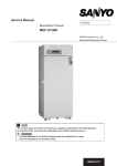
Ultra-Low Temperature Freezer
FILE No.
MDF-U55V
SANYO Electric Co., Ltd.
Biomedical Business Division
SM9910253
Effective models
This service manual is effective for following model.
Model
MDF-U55V
Product code
823 029 54
Voltage and Frequency
230/240V 50Hz
Contents
Page
----------------------------------------------
䞉Specifications
1
- Structural specifications
- Control specifications
- Performance specifications
䞉Dimensions
----------------------------------------------
4
䞉Refrigeration circuit
----------------------------------------------
5
䞉Cooling unit parts
----------------------------------------------
6
䡡Components on PCB
----------------------------------------------
7
䞉Connection on PCB
----------------------------------------------
8
䞉Electric parts
----------------------------------------------
9
䞉Specification of sensor
----------------------------------------------
10
䞉Wiring diagram
----------------------------------------------
11
䞉Circuit diagram
----------------------------------------------
12
䞉Control specifications
----------------------------------------------
13
䞉Parts layout
----------------------------------------------
28
䞉Test data
----------------------------------------------
30
- Pull-down & Pull-up data
- Pull-down temperatures
- Pull-down pressure
- Pull-down current-input
- Temperature uniformity (17points measured)
- Amount of power consumption data
- Cycle operation data
- Sample load test
䞉Instruction manual
----------------------------------------------
39
Specifications
Structural specifications
Item
Specifications
Name
Ultra-Low Temperature Freezer
Model
MDF-U55V
External dimensions
W 770 㽢 D 870 㽢 H 1990 (mm)
Internal dimensions
W 630 㽢 D 600 㽢 H 1380 (mm)
Effective capacity
519 L
Exterior
Painted steel
Interior
Painted steel
Outer door
1 door, painted steel
Inner door
2 doors, ABS resin panel with stainless frame
Insulation
Compressor
Evaporator
Condenser
Refrigerant
VIP䠄Vacuum insulation panel䠅䠇Rigid polyurethane foamed-in place
High stage side䠖Hermetic rotary type, Output: 450W
Low stage side䠖Hermetic reciprocating type, Output: 750W
High stage side: Cascade condenser
Low stage side: Tube on sheet type
High stage side䠖Fin and tube type
Low stage side䠖Cascade condenser
High stage side䠖R-404A
Refrigerating oil
Ze-NIUSL22SA
Oil additive
Oil separator
Shelf
n-pentane
SPK-0S02S2
Stainless steel, 3 shelves (adjustable)
Inner dimension䠖W 608 㽢 D 535 (mm) Load䠖50 kg/shelf
Outer door latch
1pc
Outer door lock
1pc
Caster
Access port
4pcs 䠄leveling leg 2pcs. in front side䠅
䃥17mm, 3 locations (back, bottom left, bottom right)
Refrigeration circuit
Power supply
Weight
Battery
Accessories
Optional components
Low stage side䠖R-508
Cascade system
230/240V, 50Hz, Single phase
288 kg
Nickel-metal-hydride battery, 6VDC, 1100mAh,
Auto-rechargeable (5HR-AAC)
1 set of key, 1 scraper
Inventory rack (IR-220U, IR-224U), Drawer (MDF-50R),
Temperature recorder (MTR-G85/MTR-85H)
Back-up system (CVK-UB2): LCO2, (CVK-UBN2): LN2
Interface board (MTR-480)
Data acquisition system (MTR-5000)
-1-
Control specifications
Item
Specifications
Temperature setting range
Microcomputer, key-pad input
Non-volatile memory
-50䉝~-90䉝 (Unit: 1䉝)
Temperature display
LED (Unit: 1䉝)
Temperature sensor
Pt. 1000䃈
Temperature controller
High temperature alarm
Low temperature alarm
Filter alarm
When chamber temperature deviates from set temperature+5䉝䡚+20䉝
(Factory default:+10䉝), ALARM lamp blinks and buzzer sounds after 15
minutes of delay.
Remote alarm contact: Normal Open, Normal close
Rated (max) 30VDC, 2A
Turns over after 15minutes of delay
When chamber temperature deviates from set temperature-5䉝䡚-20䉝
(Factory default:-10䉝), ALARM lamp blinks and buzzer sounds after 15
minutes of delay.
Remote alarm contact: Normal Open, Normal close
Rated (max) 30VDC, 2A
Turns over after 15minutes of delay
FILTER lamp illuminates and buzzer sounds intermittently.
Door alarm
When a door is open, DOOR lamp illuminates after predetermined delay
time elapses. (Factory default: 2minutes, Range:1~15minutes)
Power failure alarm
ALARM lamp blinks and buzzer sounds intermittently.
Remote alarm activates.
Allowable contact capacity䠖DC30V 2A䚸N.C.-COM䠈N.O.-COM
When temperature alarm or power failure alarm is occurred or any sensor
is failed, remote alarm contact turns over.
BATTERY lamp illuminates when battery accumulation time (2.8 years)
Notice of battery life
expires.
Notice of condensing fan BATTERY lamp blinks when condensing fan motor accumulation time
motor life
(5.6 years) expires.
zNotice of Battery/condensing fan motor life
zAbnormal power supply voltage
STATUS function
zAbnormal ambient temperature
zOverloaded operation
Alarm lamp: ALARM
Filter check lamp: FILTER
Battery check lamp: BATTERY
Status monitor lamp: STATUS
Door check lamp: DOOR
Buzzer stop key: BUZZER
Control panel
Alarm test key: ALARM TEST
Status key: STATUS
SET䠖Set key
: Digit shift key
: Numerical value shift key
Press digit shift key for 5 seconds to activate Key Lock mode.
Key Lock
L0: Unlock䚸L1: Lock
When temp. sensor or filter sensor or cascade sensor or AT sensor is
failed;
Self diagnosis function
Error code is displayed, ALARM lamp illuminates, buzzer sounds and
remote alarm is active.
Remote alarm
-2-
Item
Compressor protection
Compressor delay time
Specifications
Cascade sensor temperature is higher than 䠉12䉝, L side compressor
turns off.
Cascade sensor temperature is lower than 䠉34䉝, L side compressor
turns on.
Overload relay
When filter sensor temperature is higher than +60䉝, H side compressor
turns off. (Substitution for pressure switch)
Range: 3~15 minutes (Unit: 1minute)
It is not settable delay time individually between H side compressor and L
side compressor.
Performance specifications
Item
Maximum cooling performance
Temperature control range
Power source
Rated power consumption
Noise level
Specifications
-86䉝 at the center of the chamber 䠄AT䠖30䉝䚸No load䠅
䠉50䉝 to 䠉86䉝 䠄AT䠖30䉝䚸No load䠅
230V, 50Hz
240V, 50Hz
650W
700W
47dB <A> (background noise; 20dB)
Maximum pressure
2030 kPa
-3-
(Inner dimensions of tray)
Dimensions
(Inner dimensions of tray)
Top
exit of power cord
(Back side)
Side
Front
-4-
H side
L side
-5-
Dryer H
Capillary tube L
Evaporator
Cascade condenser
Dryer H
Pre-condenser
Condenser
Frame pipe
Capillary tube
(EX)
EX tank
Compressor L
Pre-condenser
Compressor H
Oil separator
Suction heat
exchanger
Capillary tube H
Accumulator
Check valve
Pre-condenser
Cascade system
Refrigeration circuit
Header
Cooling unit parts
Parts descriptions
Compressor
Power supply
Refrigeration oil
Cooling system
Condenser (type)
Condenser
Pre-condenser
Frame pipe
Evaporator 䠄Type䠅
Accumulator
Capillary tube
Resistance
Length
L
Outside diameter OD
Inside diameter ID
Refrigerant
Dryer
Condensing fan
Condensing fan motor
Specifications
H side
L side
Type䠖C-1RN45L5A
Type䠖KS240J1NS-4A1
Code䠖802 022 15
Code䠖7FB-0-M101-011-05
Single phase 230/240V, 50Hz
Single phase 230/240V, 50Hz
Kind䠖Ze-NIUSL22SA
Kind䠖Ze-NIUSL22SA
Charged q’ty䠖230cc
Charged q’ty䠖850cc
Forced air cooling 䠄Partially䠅,
Forced air cooling 䠄Partially䠅,
Pre-condenser (DSH)
Oil cooler (OC)
Fin and tube type
Cascade condenser
P6.35㽢3lines㽢12 columns,
Coil pipe (䃥6.35mm)
Fin 38pcs.
W250 mm
䇷
䇷
䃥4.76 mm
Cascade condenser
Tube on sheet type
Shell and tube, 䃥80 mm
䃥9.52 mm
䃥38 mm
Ex. capillary
0.765MPa
0.343MPa
34psi
2000 mm
2500 mm
500 mm
䃥2.0 mm
䃥2.0 mm
䃥2.4 mm
䃥0.9 mm
䃥0.9 mm
䃥1.2 mm
R-508
Charged q’ty䠖370g
R-404A
Charged q’ty䠖 432g
(TP5R3)
n-Pentane Charged q'ty䠖 18g
n-Pentane Charged q'ty䠖 53g
Type: Dry core (D-SM)
Type: 4A-XH-6 Charged q’ty䠖58g
䃥230mm, 4pcs. wings
䇷
Material䠖ABS
䇷
Type䠖SV4-11AA5P
-6-
CN11
#1-#3
Temp.sensor
CN8
#1-#2 Battery, Battery switch
#3-#4 Power transformer
CN7
#1-#2
#5-#6
#7-#8
#9-#10
Door switch
AT sensor
Filter sensor
Cascade sensor
CN1
#1-#3
Switching power supply
CN2
MTR-480 (option)
MTR-L03 (option)
CN6
Display PCB
CN9
#1-#2
H comp relay
CN4
#1-#2 Temp.control relay
#3-#4 Heater relay
CN5
#1-#5 Switch PCB
#6-#7 Buzzer PCB
CN3
Remote alarm terminal
#1 COM
#2 N.O.
#3 N.C.
Components on PCB
-7-
Connections on PCB
The following shows the connections of connectors on the Temp. controller PCB.
Connector
Connects to
Usage
CN1
Switching power supply
To supply the power to PCB.
CN2
Communication kit
To connect to MTR-480/MTR-L03(option).
Remote alarm terminal
CN3
Remote alarm contact outputs.
#1: COM.
In normal condition, open between #1 and #2
#2: N.O.
and closed between #1 and #3.
#3: N.C.
CN4
CN5
CN6
CN7
CN8
To control chamber temperature (12VDC)
#1-#2㸸Temp. control relay
To supply the power to Cap. tube heater
#3-#4㸸Heater relay
(12VDC)
#1-#5: Switch PCB
To connect to each switch
#6-#7: Buzzer
To connect to buzzer
Display PCB
To connect to each LED
#1-#2: Door switch
To control door open and close
#5-#6: AT sensor
To detect ambient temperature
#7-#8: Filter sensor
To detect temperature in condenser outlet pipe.
#9-#10: Cascade sensor
To detect temperature in cascade.
#1-#2: Battery㸦#1:6V #2:Battery switch㸧 To supply the power during power failure
#3-#4: Transformer
To supply the power to PCB.
CN9
#1-#2: H. Comp. relay
To control compressor H ON/OFF (12VDC)
CN10
Unused
CN11
#1-#3: Temp. sensor
To detect chamber temperature.
-8-
Electric Parts
MDF-U55V
Compressor (H)
Compressor (L)
Starting relay (H)
Starting relay (L)
Overload relay (L)
Starting capacitor (H)
Starting capacitor (L)
Running capacitor (H)
Running capacitor (L)
Fan motor capacitor
Condensing fan motor
Capitube heater
Temp. control relay
Heater relay
H. comp relay
Switching power supply
Battery
Temperature sensor
Cascade sensor
Filter sensor
AT sensor
Battery switch
Breaker switch
Door switch
Transformer
Noise filter
AC230/240V, 50Hz
Type
Code
Rated voltage (50/60Hz)
Winding resistance C-R(Main)
C-S(Aux)
Type
Code
Rated voltage (50/60Hz)
Winding resistance C-R(Main)
C-S(Aux)
Type
Pick up voltage
Drop out voltage
Type
Pick up voltage
Drop out voltage
Type
Action to the temp. (No current)
Action to the current (AT25Υ)
Operation time
Rating
Rating
Rating
Rating
Rating
Type
Rating
Rating
Resistance (AT25䉝)
Type
Contact capacity
Coil
Type
Contact capacity
Coil
Type
Contact capacity
Coil
Type
Input
Output
Type
Rating
Type
Rating
Type
Rating
Type
Rating
Type
Rating
Type
Rating
Model
Rating
Type
Rating
Type
Primary
Rating
Model
Rating
-9-
C-1RN45L5A
802 022 15
220-240V, 50Hz
5.95䃈
14.76䃈
KS240J1NS-4A1
7FB-0-M101-011-05
230/240V,50Hz
2.7䃈
4.9䃈
AMVL-300A
185~217VAC
60~120VAC
AMVL-300TA
205~235VAC
110VAC
MST16AJ120/61-9201
ON:120䉝 OFF:61䉝
20.5A
6~16sec.
40uF, 300VAC
160uF, 250VAC
15uF, 400VAC
12uF, 370VAC
SV4-11AA5P
220-240V, 10W
11.2W, 230V
4700ȍ
G4F-11123T
20A 250VAC
12VDC
G2R-1A-T
10A 250VAC
12VDC
G4F-11123T
20A 250VAC
12VDC
ZWS10-12/J
100-240VAC
12VDC, 0.85A
5HR-AAC-VIO3
6VDC 1100mAH
THC-663
PT1000ȍ
502AT-1
5Kȍ(25䉝)
502AT-1
5Kȍ(25䉝)
502AT-1
5Kȍ(25䉝)
SLE6A2-5
250VAC, 4A
BAM215131
250V, 15A
SDKNA20700
5VDC, 5mA
S41-U097PV
115V, 230V
9VAC, 0.46A
RSAN-2020
250VAC, 20A
Specifications of sensor
The following shows the temperature in thermal sensor (502AT-1) and its resistance value.
Temp.
(C)
Resistance
(kȐ)
Temp.
(C)
Resistance
(kȐ)
Temp.
(C)
Resistance
(kȐ)
Temp.
(C)
Resistance
(kȐ)
㸫50
154.5
㸫36
71.80
㸫22
35.65
0
13.29
㸫49
145.9
㸫35
68.15
㸫21
33.99
5
10.80
㸫48
137.8
㸫34
64.71
㸫20
32.43
10
8.84
㸫47
130.2
㸫33
61.48
㸫19
30.92
15
7.20
㸫46
123.1
㸫32
58.43
㸫18
29.50
20
6.01
㸫45
116.5
㸫31
55.55
㸫17
28.14
25
5.00
㸫44
110.2
㸫30
52.84
㸫16
26.87
30
4.17
㸫43
104.4
㸫29
50.23
㸫15
25.65
35
3.50
㸫42
98.87
㸫28
47.77
㸫14
24.51
40
2.96
㸫41
93.70
㸫27
45.45
㸫13
23.42
45
2.51
㸫40
88.85
㸫26
43.26
㸫12
22.39
50
2.13
㸫39
84.18
㸫25
41.19
㸫11
21.41
55
1.82
㸫38
79.80
㸫24
39.24
㸫10
20.48
60
1.56
㸫37
75.67
㸫23
37.39
㸫5
16.43
65
1.35
The following shows the temperature in thermal sensor (PT1000ȍ) and its resistance value.
Temp.
(C)
Resistance
(Ȑ)
Temp.
(C)
Resistance
(Ȑ)
Temp.
(C)
Resistance
(Ȑ)
㸫140
450.83
㸫70
729.99
0
1000.0
㸫130
491.47
㸫60
769.02
10
1038.0
㸫120
531.83
㸫50
807.87
20
1076.0
㸫110
571.92
㸫40
846.58
30
1113.8
㸫100
611.76
㸫30
885.13
40
1151.4
㸫90
651.38
㸫20
923.55
50
1189.0
㸫80
690.78
㸫10
961.84
60
1226.4
- 10 -
Wiring diagram
- 11 -
Circuit diagram
- 12 -
㻌
1.
2.
3.
4.
Control specifications
Key and Switch
BUZZER
:
In alarm condition, audible alarm silences when this key is pressed.
Remote alarm activates and message is not eliminated.
When a power failure is occurred (battery back-up), press this key to show a
chamber temperature for 5 seconds.
ALARM TEST
:
When this key is pressed, unit steps into Alarm Test mode with ALARM lamp
flashes, audible alarm sounds, digital LED is disappeared and remote alarm is
active.
By Auto Return function, unit will return to normal operation after approx.
90seconds elapse.
When an alarm test is performed and a battery switch is in off position, “E09”
will flash.
SET
:
Press this key to activate setting mode and 2nd digit will blink on the display.
Press this key again to store a value to be changed.
STATUS
:
Press this key when STATUS lamp illuminates to show status code (‘-- 1’, ‘--2’
and ‘--3’) on the display.
(Digit shift key)
Every time press this key to blink and change a digit among 1st, 2nd and 3rd digit
flexibly.
If this key is pressed for 5 seconds when a chamber temperature is displayed,
Key Lock is active and “L_0” is displayed.
(Numerical value
shift key)
Every time press this key to blink a digit and increase numeric value one by
one.
If this key is pressed for 5 seconds when a chamber temperature is displayed,
Function mode is active and “F00” is displayed.
Temperature control
Setting range
:
Display range
:
How to set chamber
temperature:
Unacceptable setting
range :
Key Lock mode
Setting range
:
How to set Key Lock:
Function mode
Setting range
Display range
How to set Function
mode :
-50䉝~-90䉝
-180~50
Press SET key and change a value by pressing
key and
key.
Press SET key again to memorize the value to be changed.
The value cannot be changed and audible alarm sounds for 1second, if a
value which is out of setting range is input and SET key is pressed.
0 (Unlock), 1 (Lock)
In chamber temperature display, press
key for 5 seconds to step to Key
Lock mode. (“L_0” or “L_1” is displayed. Factory default: L_0)
Change a value by pressing
key and press SET key to memorize the
value to be changed.
:
:
00~50
00~59
00, 16 and 33~43, 44~49, 51~59 are unused.
In chamber temperature display, press
key for 5 seconds to step㻌 to
Function mode and F00 is displayed.
Change a blinking 1st digit by pressing
key and
key and press SET key.
Unacceptable setting The value cannot be changed and audible alarm sounds for 1second, if a
range :
value which is out of setting range is input and SET key is pressed.
- 13 -
5.
Error codes
E01:
E02:
E03:
E04:
E05:
E06:
E07:
E08:
E09:
E10:
Temp. sensor is open circuited
Temp. sensor is short circuited
Cascade sensor is open circuited
Cascade sensor is short circuited
Filter sensor is open circuited
Filter sensor is short circuited
AT sensor is open circuited
AT sensor is short circuited
Battery switch is in off position
Compressor temperature is abnormal
(1) Temp. sensor
Open circuit (E01): When a temp. sensor temperature is higher than 50䉝, E01 and 50䉝 are
displayed alternately and audible alarm sounds intermittently and remote
alarm contact is active.
Compressor is forcible to turn on.
Press BUZZER key to silence audible alarm.
Short circuit (E02): When a temp. sensor temperature is lower than -170䉝, E02 and -170䉝~
-180䉝 are displayed alternately and audible alarm sounds intermittently and
remote alarm contact is active.
Compressor is forcible to turn on.
Press BUZZER key to silence audible alarm.
(2) Cascade sensor
Open circuit (E03): When a temperature in cascade sensor is lower than -65 䉝 , E03 and
chamber temperature are displayed alternately, audible alarm sounds
intermittently and remote alarm contact is active.
Both High and Low side compressors are turned off.
Press BUZZER key to silence audible alarm.
Short circuit (E04): When a temperature in cascade sensor is higher than 60 䉝 , E04 and
chamber temperature are displayed alternately, audible alarm sounds
intermittently and remote alarm contact is active.
Both High and Low side compressor are turned off.
Press BUZZER key to silence audible alarm.
(3) Filter sensor
Open circuit (E05): When a filter sensor temperature is lower than -60䉝, E05 and chamber
temperature are displayed alternately, audible alarm sounds intermittently
and remote alarm contact is active.
High side compressor is forcible to turn off.
Press BUZZER key to silence audible alarm.
Short circuit (E06): When a temperature in filter sensor is higher than 130䉝, E06 and chamber
temperature are displayed alternately, audible alarm sounds intermittently
and remote alarm contact is active.
Press BUZZER key to silence audible alarm.
(4) AT sensor
Open circuit (E07): When a temperature in AT sensor is lower than -60䉝, E07 and chamber
temperature are displayed alternately, audible alarm sounds intermittently
and remote alarm contact is active.
Press BUZZER key to silence audible alarm.
Short circuit(E08): When a temperature in AT sensor is higher than 60䉝, E08 and chamber
temperature are displayed alternately, audible alarm sounds intermittently
and remote alarm contact is active.
Press BUZZER key to silence audible alarm.
(5) Battery SW is in
off position (E09):
If you press ALARM TEST key when battery switch is in off position or
battery is unconnected, E09 is displayed.
- 14 -
(6)Compressor
abnormal
temperature (E10):
When a temperature in filter sensor is higher than 60䉝, E10 and chamber
temperature are displayed alternately and high side compressor is forcibly
turned off to notify compressor temperature is abnormal or fan motor is
locked.
Press BUZZER key to silence audible alarm.
When the temperature obtained from filter sensor temperature subtracts
ambient temperature, is equal or lower than 10䉝, compressor will turn on.
(7) Error code priority
No.1:
No.2:
No.3:
No.4:
No.5:
6.
7.
Warning functions
Door alarm
:
Cascade sensor error (E03, E04) … Compressor is forcible to turn off
Filter sensor error (E05, E06) … Impossible to protect compressor
Abnormal compressor temperature(E10) … Compressor temporary turns off
Temp. sensor error (E01, E02) … Compressor keeps turning on
AT sensor error (E07, E08) … Warming-up operation is forcible to be active
When an outer door leaves open, DP54 (red lamp) illuminates. Audible alarm
sounds intermittently after 1~15 minutes (Factory default: 2 minutes) elapse.
Audible alarm is not active simultaneously with remote alarm.
Press BUZZER key to silence audible alarm.(Ring Back is not active)
High temp. alarm
:
When chamber temperature is equal or higher than set temperature + high
temp. alarm set temperature +1, ALARM lamp and LED flash, audible alarm
sounds intermittently and remote alarm is active after 10 minutes elapse.
When chamber temperature is equal or lower than set temperature, ALARM
lamp and LED go off, audible alarm silences, and remote alarm turns off.
Press BUZZER key to silence audible alarm, but not to activate remote alarm
simultaneously.
Low temp. alarm
:
When chamber temperature is equal or lower than set temperature - low
temp. alarm set temperature -1, ALARM lamp and LED flash, audible alarm
sounds intermittently and remote alarm is active after 10 minutes elapse.
When chamber temperature is equal or higher than set temperature, ALARM
lamp and LED go off, audible alarm silences, and remote alarm turns off.
Press BUZZER key to silence audible alarm, but not to activate remote alarm
simultaneously.
Power failure alarm
:
If a power failure is occurred or a power interrupts for 3 seconds when
battery switch is in on-position, ALARM lamp blinks, audible alarm sounds
intermittently and remote alarm is active.
Press BUZZER key to display chamber temperature for 5 seconds.
When a power returns within 3 seconds since the power was interrupted,
microprocessor resets in default settings. Remote alarm is not active.
Press BUZZER key to silence audible alarm, but remote alarm keeps active.
Remote alarm will keep active until chamber temperature is stabled after the
power returns from power failure.
When a power interrupts, press BUZZER key to see chamber temperature
for 5 seconds.
Other functions
Auto Return
:
If there are not any key operations for 90 seconds when setting mode or Key
Lock mode or Function mode is active, unit automatically returns to chamber
temperature display.
Ring Back
:
Audible alarm will sound after predetermined setting time elapses if it is
silenced by someone pressing BUZZER key.
- 15 -
Display of
temperature:
sensor
F12: 3 digits display of temp. sensor temperature (Unit:0.1䉝)
(Ex. -80.2䉝㻌 䊻㻌 Displayed as ‘80.2’)
F13: 3 digits display of cascade sensor temperature (Unit:1䉝)
(Ex. 67䉝㻌 䊻㻌 Displayed as ‘067’)
F14: 3 digits display of filter sensor temperature (Unit:1䉝)
(Ex. 67䉝㻌 䊻㻌 Displayed as ‘067’)
F15: 3 digits display of AT sensor temperature (Unit:1䉝)
(Ex. 30䉝㻌 䊻㻌 Displayed as ‘030’)
Battery accumulation F03: 3 digits display of battery accumulation time
time
:
(Ex. 2years and 6months accumulated 䊻㻌 Displayed as ‘02.5’)
When battery accumulation time (2years and 8months, ’02.8’) expires,
BATTERY lamp illuminates.
<Reset of battery accumulation time>
Step to F06 and change a value to ‘409’. Press SET key to reset
accumulation time to ’00.0’. BATTERY lamp goes off.
Condensing fan
motor accumulation
time
:
F32: 3 digits display of Condensing fan motor accumulation time
(Ex. 5years and 6months accumulated 䊻 Displayed as ’05.5’)
When condensing fan motor accumulation time (5years and 6monts,
‘05.6’) expires, BATTERY lamp flashes.
<Reset of battery accumulation time>
Step to F06 and change a value to ‘410’. Press SET key to reset
accumulation time to ’00.0’. BATTERY lamp goes off.
Forcible operation of F18: Compressor is turned off and capillary heater is forcibly to turn on when
capillary heater:
a value is changed to ‘000” in F18.
Capillary heater is forcibly to turn off once inputting ‘000’ again during a
power conducting to capillary heater.
It is impossible to conduct a power to capillary heater when a value is
changed to ‘001’.
Only compressor will be turned on every 18 hours.
ROM version
8.
:
F30: Display of current ROM version
(Ex. Ver. 1.00 䊻㻌 Displayed as “1.00”)
STATUS function
(1) Display of STATUS code
STATUS lamp illuminates in the following conditions.
STATUS code will be displayed by pressing STATUS key when STATUS lamp
illuminates.
STATUS 1: When an ambient temperature is higher than 35.0䉝, or lower than 0䉝, ‘--1’
is appeared on the display.
STATUS 2: When a power supply voltage is lower than 2.01VDC between TP7 and TP3,
‘-- 2’ is appeared on the display.
STATUS 3: When running rate is higher than 95%, ‘--3’ is appeared on the display.
- 16 -
(2) Display sequence of STATUS code
(Ex.1) When all of three STATUS codes occur simultaneously;
‘ --‘
=>
‘-- 1’ =>
‘-- 2’
=> 㻌 ‘-- 3’
=>
‘--1’ …
(Ex.2) When STATUS 1 and 2 occur simultaneously;
‘ --‘
=>
‘-- 1’
=>
‘-- 2’
=> 㻌 ‘-- 2’
=>
‘--1’ …
When it elapses 90 seconds or when a unit returns from STATUS condition, chamber
temperature will be appeared on the display.
9.
Running rate
Running rate: Obtained from (ON time / (ON time + OFF time)) x 100%
Definition: “ON time” means the reach time until P3.1 in IC5 is changed “Low” to “Hi”
“OFF time” means the reach time until P3.1 in IC5 is returned “Hi” to “Low”
Condition to measure running rate:
Cycle operation will start when a compressor turns on for the first time after it was
turned off when chamber temperature was lower than set temperature.
Running rate will be measured after 2 hours elapse since the unit was stabilized
in cycle operation.
ON time (Min.) = The time until P3.1 in IC5 first reaches from LOW to HIGH
OFF time (Min.) = The time until P3.1 in IC5 reaches from HIGH to LOW
Condition to calculate running rate:
ON time
OFF time
Running rate
=0
=0
Impossible to calculate
>0
=0
(0%)
=0
>0
>0
>0
0 ~ 100%
Note) Running rate cannot be measured when a chamber temperature is higher than set
temperature + 4.0䉝.
Measuring should be done until a chamber temperature is stabilized.
Diagnosed value of overload running rate:
Step to F20 and input ‘000’.
Compressor turns on
Chamber
temperature
for the first time.
Start to cycle run
Start to measure
running rate
Start to measure
running rate
Set
Compressor turns off
for the first time
Chamber temperature
2 hours
8 hours
Unit is stabilized in cycle operation.
reaches set temperature.
- 17 -
Running rate is measued every 8
hours until chamber temperature is
over set temperature+4.0䉝
Diagnosed running rate
=(-(Set temp.)X0.9)+((ATX0.9-4.5䉝))-((Set temp.+85䉝) / 10))
You can know running status by the calculation for diagnosed running rate.
Diagnosis is done by comparing running rate for 8 hours operation after 2 hours
elapses since unit started cycle operation, with diagnosed running rate.
(Diagnosed running rate – running rate) < 0 … Normal (DP52 goes off)
(Diagnosed running rate – running rate) 䍻0 … Overload operation (DP52 illuminates)
222 = Running rate cannot be obtained by calculation. (DP52 goes off)
Diagnosis is done in every 8 hours.
10.
Function mode
F00
Display of chamber temperature (Unused)
F01
Setting of high temperature alarm
F02
Setting of low temperature alarm
F03
Display of battery accumulation time
F04
Setting of door alarm delay time
F05
Setting of compressor delay time
F06
Setting of service code (Code: 384), Reset of accumulation time
F07 *
Temperature sensor Zero Adjustment
F08 *
Cascade sensor Zero Adjustment
F09 *
Compressor continuous running mode … Factory test mode (Unused)
F10 *
Program running mode … Factory test mode (Unused)
F11 *
PCB test mode … Factory test mode (Unused)
F12 *
Display of temperature in temp. sensor
F13 *
Display of temperature in cascade sensor
F14 *
Display of temperature in filter sensor
F15 *
Display of temperature in AT sensor
F16 *
Display of chamber temperature (Unused)
F17 *
Display of model code and initialization of non-volatile memory
F18 *
Forcible operation for capillary heater
F19 *
Setting of capillary heater ON time … Factory use
F20 *
Setting of diagnosed value of overload running ratio … Factory use
F21
Setting of communication ID
F22
Setting of communication mode
F23 *
Display of power supply voltage
F24
Remote alarm terminal output
F25
Setting of Ring Back time
F26 *
Display of actual operation ratio
F27 *
Display of diagnosed value for overload running ratio
F28 *
Display of delay time of permission to measure running rate (2 hrs timer)
F29 *
Display of delay time of permission to measure running rate (8 hrs timer)
F30 *
Display of ROM version
F31 *
Setting of filter alarm
F32
Display of condensing fan motor accumulation time
F33~F43 Unused
F44 *
Adjustment of power supply voltage display
F45~F49 Unused
F50
Setting of alarm delay time
F51~F59 Unused
Input service code ‘384’ in F06 prior to use function codes which are marked with *.
To cancel service code, input “000” in F06 or turn the power off.
Setting
procedure:
In chamber temperature display, press
key for 5 seconds to display “F00”.
Input Function code by pressing
key and
key.
Press SET key to be function mode available.
- 18 -
F00:
<Purpose> Simply passing through if entered by mistake.
<Operation> Press SET key in “F00” display to return to chamber temperature
display.
F01:
<Purpose> Setting of high temperature alarm
<Operation> Input F01 and press SET key to display “015” (Factory default).
Setting range is ‘005~020’.
Change a value by pressing
key.
Press SET key to memorize the value and to return to chamber
temperature display.
F02:
<Purpose> Setting of low temperature alarm
<Operation> Input F02 and press SET key to display “-10” (Factory default).
Setting range is “-05”~“-20”.
Change a value by pressing
key.
Press SET key to memorize the value and to return to chamber
temperature display.
F03:
<Purpose> Display of battery accumulation time
<Operation> Input F03 and press SET key to display alternately F03 with “00.0” (in
case battery used for 36days or less).
Press SET key to return to chamber temperature display.
F04:
<Purpose> Setting of door alarm delay time
<Operation> Press SET key in “F04” to display ‘002’ (Factory default).
setting range is ‘001’~’015’.
Change a value by pressing
key and
key.
Press SET key to memorize the value and to return to chamber
temperature display.
F05:
<Purpose> Compressor turns on with delay when a power is supplied or a power
returns from a power failure.
<Operation> Input “F05” and press SET key to display ‘003’ (Factory default).
Setting range is ‘003’~’015’. (Unit: Minute)
Change a value by pressing
key and
key.
Press SET key to memorize the value and to return to chamber
temperature display.
F06:
<Purpose> Input of service code and reset of accumulation time
<Operation> Input F06 and press SET key to display ‘000’ (Factory default).
Set service code to “384” by pressing
key and
key.
Press SET key to memorize the value and to return to chamber
temperature display.
<Reset of battery accumulation time>
Input service code ‘384’ in F06.
Input ‘409’ to reset battery accmulation time and to return to chamber
temperature display. (Service code is cancelled)
<Reset of condensing fan motor accumulation time>
Input service code ‘384’ in F06.
Input ‘410’ to reset fan motor accumulation time and to return to
chamber temperature display. (Service code is cancelled)
<Cancel> Input F06 again and press SET key to display ‘384’.
Change to ‘000’ by pressing
key and
key.
Press SET key to memorize the value and to return to chamber
temperature display.
Turn a power off then on to change a value to ‘000’, but it is not stored
in non-volatile memory.
Note) Service code ‘384’ is stored in non-volatile memory during battery
back-up.
- 19 -
F07:
<Purpose> To match a temp. sensor temperature with 1/2H air temperature
(Zero calibration of temp. sensor)
<Operation> Input service code in F06 prior to use this mode.
Input F07 and press SET key to display ‘00.0’ (Factory default).
Setting range is ‘-4.9’~’04.9’.
Change a value by pressing
key and
key.
Press SET key to memorize the value and to return to chamber
temperature display.
F08:
<Purpose> To calibrate a cascade sensor temperature
<Operation> Input service code in F06 prior to use this mode.
Input F08 and press SET key to display ‘00.0’ (Factory default).
Setting range is ‘-9.9’~’09.9’.
Change a value by pressing
key and
key.
Press SET key to memorize the value and to return to chamber
temperature display.
F12:
<Purpose> To display a temp. sensor temperature
<Operation> Input service code in F06 prior to use this mode.
Input F12 and press SET key to display alternately F12 and “XX.X”
(chamber temperature). Press SET key to return to chamber
temperature display. Decimal point is displayed in the 3 digits indication,
but minus “-“ is not displayed.
Ex) “-79.5䉝” 䊻㻌 Indicated as “79.5”
F13:
<Purpose> To display a cascade sensor temperature
<Operation> Input service code in F06 prior to use this mode.
Input F13 and press SET key to display alternately F13 and “XXX”
(present temperature in cascade sensor). Press SET key to return to
chamber temperature display.
F14:
<Purpose> To display a filter sensor temperature
<Operation> Input service code in F06 prior to use this mode.
Input F14 and press SET key to display alternately F14 and “XXX”
(present temperature in filter sensor). Press SET key to return to
chamber temperature display.
F15:
<Purpose> To display an AT sensor temperature
<Operation> Input service code in F06 prior to use this mode.
Input F15 and press SET key to display alternately F15 and “XXX”
(present temperature in AT sensor). Press SET key to return to
chamber temperature display.
F16:
<Purpose> Simply passing through if entered by mistake
<Operation> Press SET key in “F16” to return to chamber temperature display.
F17:
<Purpose> Display of model code and initialization of non-volatile memory
<Operation> Service code should be input in F06 prior to use this mode.
Input F17 and press SET key to display ‘00X’.
Change a value by pressing
key.
Press SET key to memorize and return to chamber temperature display.
Model code ‘008’: MDF-U55V
- 20 -
<Initial values in non-volatile memory>
Zero Adjustment value for temperature sensor
Zero Adjustment value for cascade sensor
Capillary heater ON time
Auto Return
Chamber set temperature
Door alarm delay time
High temp. alarm
Low temp. alarm
Compressor delay time
Communication ID
Communication mode
Key Lock
Linkage between remote alarm and buzzer
Buzzer tone for filter alarm
Diagnosed value for STATUS 3
: 0䉝
: 0䉝
: 8 minutes
: 30 minutes
: -80䉝
: 2 minutes
: +10䉝
: -10䉝
: 3 minutes
: 000
: 000
: OFF
: OFF
: OFF
: Fixed
F18:
<Purpose> Forcible operation for capillary heater
<Operation> Service code should be input in F06 prior to use this mode.
Input F18 and Press SET key to display ‘000’ (Factory default).
Change to alternative value ‘000’ or ‘001’ by press
key and
key.
Press SET key to memorize the value and return to chamber
temperature display.
000: Capillary heater is forcibly turned on, or
Capillary heater is forcibly turned off
001: Capillary heater is inoperative
F21:
<Purpose> Setting of serial communication ID
<Operation> Input F21 and press SET key to display ‘000’ (Factory default).
Setting range is ‘001’ ~ ‘255” by pressing
key and
key.
Press SET key to return to chamber temperature display.
<Serial communication data>
Data
Chamber temperature
Cascade temperature
Power supply voltage
Filter temperature
Ambient temperature
Door
Capillary heater
Compressor H
Compressor L
Power failure
Running ratio
Diagnosed value for overload operation
2H timer counting
8H timer counting
Set temperature
High temp. alarm set value
Low temp. alarm set value
Filter lamp
Remote alarm
Status lamp
Remote control of set temperature
- 21 -
Display
-180.0 ~ +50.0
-68.0 ~ +89.0
0.0 ~ 120.0
-68.0 ~ +160.0
-68.0 ~ +89.0
0/100
0/100
0/100
0/100
0/100
0~100, 222
0~100, 999
0~120
0~480
-90.0~-50.0
+5.0~+20.0
-5.0~-20.0
0/50
0/50
0/50
-90.0~-50.0
Unit
䉝
䉝
㻑
䉝
䉝
Close/Open
Off/On
Off/On
Off/On
Off/On
%
%
Minute
Minute
䉝
䉝
䉝
Off/On
Off/On
Off/On
䉝
F22:
<Purpose> Setting of serial communication mode
<Operation> input F22 and press SET key to display ‘000’ (Factory default)
Change a value by pressing
key and
key.
Press SET key to memorize the value and return to chamber
temperature display.
Control mode (the 3rd digit)
0: Local (initial)
1: Remote
Baud rate (the 2nd digit)
0: 2400bps (initial)
1: 4800bps
2: 9600bps
Note) Setting value cannot be changed at control panel if control mode
is set to ‘Remote’.
F23:
<Purpose> To display a power supply voltage (Unit: %)
<Operation> Service code should be input in F06 prior to use this mode.
Input F23 and press SET key to display alternately F23 with ‘xxx’
(present power supply voltage). Press SET key to return to chamber
temperature display.
F24:
<Purpose> Linkage between remote alarm and buzzer
<Operation> Input F24 and Press SET key to display ‘000’ (Factory default).
Change a value by pressing
key.
Press SET key to memorize the value and return to chamber
temperature display.
000: Remote alarm does not link with buzzer
001: Remote alarm links with buzzer
F25:
<Purpose> Setting of Ring Back time
<Operation> Input F25 and press SET key to display “030” (Factory default).
Setting range is ‘000’~’060’.
Change a value by pressing
key.
Press SET key to memorize the value and to return to chamber
temperature display.
000: Not Ring Back
010: 10 minutes
020: 20 minutes
030: 30 minutes
040: 40 minutes
050: 50 minutes
060: 60 minutes
F26:
<Purpose> Display of running ratio (Unit: %)
<Operation> Service code should be input in F06 prior to use this mode.
Input F26 and press SET key to display alternately F26 with “XXX”
(Present running rate).
Press SET key to return to chamber temperature display.
F27:
<Purpose> Display of diagnosed value for overload running ratio
<Operation> Service code should be input in F06 prior to use this mode.
Input F27 and press SET key to display alternately F27 with “XXX”
(present diagnosed value for overload running ratio).
‘000’ is displayed before it accumulates 480 minutes in 8H timer.
Factory default is ‘095’ which is the fixed, except in case diagnosed
value is obtained from calculation in F20.
Press SET key to return to chamber temperature display.
- 22 -
F28:
<Purpose> Display of delay time to start measuring running ratio
(2hrs timer; 000~120 min)
<Operation> Service code should be input in F06 prior to use this mode.
Input F28 and press SET key to display alternately F28 with ‘xxx’
(present count value for delay time to start measuring running rate).
Press SET key to return to chamber temperature display.
When a delay time expires (a value reaches to ‘120’), unit will start
measuring running ratio.
F29:
<Purpose> Display of delay time to start diagnosing running ratio
(8hrs timer; 000~480 min)
<Operation> Service code should be input in F06 prior to use this mode.
Input F29 and press SET key to display alternately F29 with ‘xxx’
(present counting value for delay time to start diagnosing running ratio).
Press SET key to return to chamber temperature display.
8hours timer start counting after 2hours timer expires.
When a delay time expires (a value reaches to ‘480’), unit will start
diagnosing running ratio.
F30:
<Purpose> ROM version is displayed
<Operation> Service code should be input in F06 prior to use this mode.
Input F30 and press SET key to display alternately F30 with “X.XX”
(present ROM version).
Press SET key to return to chamber temperature display.
F31:
<Purpose> Setting of buzzer during filter alarm occurs
<Operation> Service code should be input in F06 prior to use this mode.
Input F31 and press SET key to display “001” (Factory default).
Change to alternative value ‘000’ or ‘001’ by pressing
key.
Press SET key to revert to chamber temperature display.
000: Off
001: On
F32:
<Purpose> Display of accumulation time of condensing fan motor
<Operation> Service code should be input in F06 prior to use this mode.
Input F32 and press SET key to display alternately F32 with ‘xx.x’
(accumulation time).
Press SET key to return to chamber temperature display.
F44:
<Purpose> Adjustment for difference of power supply voltage
<Operation> Input F44 and press SET key to display ‘000’ (Factory default).
Setting range is ‘000’~’003’.
Press SET key to return to chamber temperature display.
Input value
000
001
002
003
F50:
Adjustment of display
0% (Power supply voltage is not increased)
3% increased
5% increased
7% increased
<Purpose> Setting of alarm delay time
<Operation> Input F50 and press SET key to display ‘015’ (Factory default).
Setting range is ‘000’~’015’.
Change a value by pressing
key and
key.
Press SET key to memorize the value and to return to chamber
temperature display.
- 23 -
11.
Compressor control (differential) value
Compressor H:
Turns on when a chamber temperature is set temperature -0.4䉝.
Compressor L:
1) Turns on when compressor H turns on and a cascade sensor temperature is -34䉝.
2) Turns on after 3 minutes elapse since compressor H turned on
Compressor H, L:
Turns off when a chamber temperature is set temperature -1.6䉝
Interval:
1 minute *
* ‘Interval’ means that a period one of compressor either H or L turns on after another one was
turned on.
Note) Compressor L does not turn on until 1 minute elapses since compressor H turned on,
if a temperature in cascade sensor is lower than -34䉝.
1min or over
PV=SV-0.4
Chamber
temp.
(䠬䠲)
3min. or over
䠄Comp. delay䠅
1min or over
PV=SV-0.4
PV=SV-1.4
3min. or over
䠄Comp. delay䠅
PV=SV-1.4
SV
SV-0.4䉝
CT=-34䉝
Cascade
temp.
(CT)
CT=-34䉝
SV-1.4䉝
CT=-34䉝
Comp. H
Comp. L
Comp. H&L OFF
Comp. L ON
Comp. H&L OFF
Comp. L ON
Comp. H ON
Comp. H ON
<Operational chart of compressor H/L during cycle>
Protection for compressor H:
Compressor H turns off to prevent it from being warmed up that is caused by fan motor lock.
Filter sensor temperature:
Compressor H turns off when a filter sensor temperature is higher than 60䉝. It will turn on again
when the filter sensor temperature is lower than ambient temperature +10䉝.
- 24 -
12.
Delay time
Compressor delay time (Factory default: 3 minutes)
Compressor H or L will be active after predetermined delay time elapses in case it turned off during
cycle operation. Compressor delay time is changeable in F05.
Temperature alarm delay time (Factory default: 15 minutes)
When high or low temperature alarm is triggered, buzzer and remote alarm are active after
predetermined delay time elapses. Temperature alarm delay time is changeable in F01(high temp.
alarm) or F02 (low temp. alarm).
* Note) ALARM lamp illuminates and “F01” or “F02” is displayed without delay.
Door alarm delay time (Factory default: 2 minutes)
When an outer door is ajar, audible alarm sounds after predetermined delay time elapses.
Door alarm delay time is settabled in F04.
Power failure alarm delay time (3 seconds fixed)
When a power is interrupted by power failure, power failure alarm will be occurred after 3 seconds
elapses.
Power failure alarm delay time is unchangeable.
13.
Prevention for oil logging in capillary
Purpose:
Capillary heater which mounts on capillary is powered and both compressor H and L are turned off
to prevent capillary from oil logging.
Action:
Both compressor H and L are turned off and capillary heater relay (CN4: 3-4) is active.
Frequency:
8 minutes in every 18 hours (Setting time are changeable in F19)
Timing of action:
(1) After 9 seconds elapses since both compressor H and L are turned off during cycle operation.
(2) Forcible termination of operation for both compressor H and L if they keep running for 60
minutes after they were ordered to stop operation.
Forcible operation of capillary heater:
Forcible operation of capillary heater is settable in F18.
14.
Sensor offset
Offset value:
(1) Temperature sensor: +1.3䉝 (Changeable in F07)
(2) Cascade sensor: +/-0.0䉝 (Changeable in F08)
(3) Filter sensor: +/-0.0䉝
(4) AT sensor: +/-0.0䉝
15.
Remote alarm terminal
Operation:
When a unit is in alarming condition, remote alarm contact (RLY2) switches the position.
CN3
Normal
In alarm
Between 1 and 2
(N.O.)
Open
Close
Between 1 and 3
(N.C.)
Close
Open
- 25 -
16.
Actions and settings after reset
Actions and settings when a power is supplied (Power on reset)
Alarm
Compressor
Remote alarm
Ring Back
Door alarm delay time
Timer
2H, 8H timer
Counting time during compressor L is inactive
Setting data
Off
Off
Off
30 minutes
2 minutes
Reset
Reset (0)
Reset
Read by non-volatile memory
Momentary power interruption:
When a chamber temperature is lower than set temperature+10䉝, it is diagnosed that unit is
in momentary power interruption.
Actions and settings after unit retrieves from power failure alarm:
Alarm
Compressor
Remote alarm
Door alarm delay time
Timer
2H, 8H timer
Counting time during compressor L is inactive
Setting data
17.
Off
Off
On
2 minutes
Reset
Reset (0)
Reset
Read by non-volatile memory
Lamp and display
Lamp specifications:
<Control PCB>
Lamp
Color
DP1
Orange
DP2
Green
DP3
Red
Lamp status
On
Off
On
Off
On
Off
DP4
DP6
Green
<Display PCB>
Lamp
Color
DP51
Red
DP52
Green
DP53
Orange
DP54
Red
DP55
DP56
Orange
On
Off
Lamp status
Flash
On
On
On
On
Flash
Unit status
Not in alarm
High/low temp. alarm, sensor failure, power failure
Compressor L is active
Compressor L is inactive
Capillary heater is active
Capillary heater is inactive
(Unused)
Compressor H is active
Compressor H is inactive
Unit status
Alarming
Status 1 or 2 or 3 is occurred
Filter alarm is occurred
Door is ajar
Notice of battery life
Notice of fan motor life
(Unused)
- 26 -
Examples of display:
Chamber temp.
Set temp.
Function㻌 㻌 㻌
-79.5䉝
-80.0䉝
F03
Decimal point of chamber temp. -80.0
Sensor offset㻌 㻌 㻌
-5.0
Operation monitoring㻌 㻌 LCP
Service code㻌 㻌 㻌 384
Error
Set value㻌 㻌 㻌
004
Accumulation time㻌 㻌 8H timer 135
Key Lock㻌 㻌 㻌
L_0
Buzzer tone:
Alarms (except door alarm)
Key operation
Set value memory
Out of settable range
Door alarm
㻌㻌㻌㻌
E01
Intermittent tone
Click tone
Click tone
Continuous tone (1 second)
Intermittent tone (Shorter interval than other alarms)
- 27 -
Parts layout
Control panel
Inner door handle
Temp. sensor with cover
Door latch "Close"
Door latch "Open"
Temp. sensor
without cover
Filter
AT sensor
- 28 -
<Cooling unit - Rear bottom side>
Oil separator
Compressor L
<Cooling unit - Left bottom side>
Compressor H
Condensing fan motor
Oil separator
Filter sensor
Fan motor condenser
12P terminal
Remote alarm terminal
Breaker switch
Battery switch
<Electric Box - Right bottom side>
Heater relay
Transformer
Starting relay L
H comp relay
Switching power supply
Starting relay H
Temp. controller PCB
Temp. control relay
Starting capacitor L
Starting capacitor H
Running capacitor L
Running capacitor H
- 29 -
Test data
Note) Following data are the reference only.
AT30䉝 Pull-down & Pull-up Temperture
40
230V50Hz䚷Pull-down
Temperature[䉝]
20
Pull-up
0
-20
-40
-60
-80
-100
0
2
4
6
8
10
Time[hour]
AT35䉝 Pull-down Tempertures
60
1/2䠤
40
H䚷EVA䚷OUT
Temperature[䉝]
20
L EVA䚷IN
0
L䚷EVA䚷OUT
-20
-40
-60
-80
-100
-120
0
2
4
6
Time[hour]
- 30 -
8
10
AT35䉝䚷Pull-down Pressure䚷䠄1ij230V50Hz䠅
4
Pressure[MPa]
㻴㼋㻼㼐㼇㻹㻼㼍㼉
3.5
㻴㼋㻼䡏㼇㻹㻼㼍㼉
3
㻸㼋㻼㼐㼇㻹㻼㼍㼉
㻸㼋㻼䡏㼇㻹㻼㼍㼉
2.5
2
1.5
1
0.5
0
0
2
4
Time[hour]
6
8
10
10
900
9
800
8
700
7
Input[W]
600
6
W䚷䠄50Hz䠅
500
5
A䚷䠄50Hz䠅
400
4
300
3
200
2
100
1
0
0
0
1
2
3
4
Time[hour]
- 31 -
5
6
7
Current[A]
AT35䉝䚷Pull-down䚷Current-Input
1000
Temperature uniformity - 17points measuring
Notes) These data are the reference only.
Back
Top of interior
(2)
(4)
Upper area measuring points
(5)
Front
(3)
(1)~(4): 69mm(H)lower from "Top of interior",
30mm(D) away and 43mm(W) away
from each corner
10mmH
(5): Center and 69mm(H) lower from
"Top of interior"
69mm᳂
(1)
(16)
Upper shelf
(16): Center and 10mm(H) upper from
"Upper shelf"
43mmW
(7)
(6)
Middle shelf
30mmD
(9)
(10)
(8)
Middle area measuring points
H
10mmH
Mullion
(6)~(9): 10mm(H) upper from "Middle shelf",
30mm(D) away and 43mm(W) away
from each corner
(10): Center and 10mm(H) upper from
"Middle shelf"
(17)
10mmH
D
Lower shelf
Bottom area measuring points
᳑
(12)
(14)
(15)
(11) Bottom of interior
(13)
69mm᳂
(11)~(14): 69mm(H) upper from "Bottom of
interior", 30mm(D) away and
43mm(W) away from each corner
(15): Center and 69mm(H) upper from "Bottom
of interior"
(17): Center and 10mm(H) upper from "Lower
shelf"
Left
Right
- 32 -
Temperature Uniformity (Reference Data)
䠘Conditions䠚
Ambient temperature: 20/30䉝
Load: Unloaded
䠘Temperature distribution䠚
Temperature of the cycle in each area (SV=-80䉝䚸air temperature)
䐟
䐠
䐡
䐢
䐣
䐤
䐥
䐦
䐧
䐨
䐩
䐪
䐫
䐬
䐭
䐮
䐯
Left front
Left back
Right front
Right back
Center
Left front
Left back
Right front
Right back
Center
Left front
Left back
Right front
Right back
Center
Center of Upper shelf
Center of Lower shelf
Average
Ambient temperature 30䉝
230V/50Hz
Middle of
Maximum Minimum
Differential
cycle
-75.0
-79.1
-77.1
±2.1
-76.8
-81.3
-79.1
±2.3
-74.7
-79.5
-77.1
±2.6
-76.8
-81.6
-79.2
±2.4
-77.1
-82.2
-79.7
±2.4
-77.7
-80.0
-78.9
±1.2
-79.5
-82.2
-80.9
±1.4
-77.4
-79.7
-78.6
±0.9
-79.3
-82.1
-80.7
±1.2
-79.0
-80.7
-79.9
±1.4
-76.2
-79.1
-77.7
±1.5
-77.7
-80.9
-79.3
±1.6
-77.5
-80.9
-79.2
±1.5
-78.4
-82.0
-80.2
±1.7
-78.4
-81.4
-79.9
±1.8
-78.8
-80.6
-79.7
±0.9
-79.5
-81.0
-80.3
±0.8
-79.2
-
Bottom area Middle area Upper area
Left front
Left back
Right front
Right back
Center
Left front
Left back
Right front
Right back
Center
Left front
Left back
Right front
Right back
Center
Center of Upper shelf
Center of Lower shelf
Average
Bottom area Middle area Upper area
䐟
䐠
䐡
䐢
䐣
䐤
䐥
䐦
䐧
䐨
䐩
䐪
䐫
䐬
䐭
䐮
䐯
Unit:䉝
Ambient temperature 20䉝
230V/50Hz
Middle of
Differential
Maximum Minimum
cycle
-75.7
-81.0
-78.4
±2.7
-77.7
-84.2
-81.0
±3.3
-73.7
-80.2
-77.0
±3.3
-77.0
-83.6
-80.3
±3.3
-76.7
-81.7
-79.2
±2.5
-78.1
-80.6
-79.4
±1.3
-80.0
-83.2
-81.6
±1.6
-78.0
-80.6
-79.3
±1.3
-79.8
-83.2
-81.5
±1.7
-79.7
-81.9
-80.8
±1.1
-77.0
-79.4
-78.2
±1.2
-77.8
-80.6
-79.2
±1.4
-76.4
-78.5
-77.5
±1.1
-77.0
-79.9
-78.5
±1.5
-78.3
-80.7
-79.5
±1.2
-80.0
-82.0
-81.0
±1.0
-80.0
-81.3
-80.7
±0.6
-79.6
-
Note:This data does not represent a guarantee of product performance.
䠘Amount of power consumption䠚
Amount of power consumption when driving at cycl (SV=-80䉝䠅
Ambient temp. 20䉝
230V/50Hz
11.08
- 33 -
Unit䠖kWh/day
Ambient temp. 30䉝
230V/50Hz
12.63
䠘Temperature distribution䠚
Temperature of the cycle in each area (SV=-70䉝䚸air temperature)
䐟
䐠
䐡
䐢
䐣
䐤
䐥
䐦
䐧
䐨
䐩
䐪
䐫
䐬
䐭
䐮
䐯
Left front
Left back
Right front
Right back
Center
Left front
Left back
Right front
Right back
Center
Left front
Left back
Right front
Right back
Center
Center of Upper shelf
Center of Lower shelf
Average
Ambient temperature 30䉝
230V/50Hz
Middle of
Maximum Minimum
Differential
cycle
-68.6
-77.4
-73.0
±4.4
-66.9
-73.9
-70.4
±3.5
-65.6
-72.9
-69.3
±3.7
-68.0
-76.5
-72.3
±4.3
-67.5
-75.0
-71.3
±3.8
-66.0
-69.8
-67.9
±1.9
-69.0
-74.6
-71.8
±2.8
-65.5
-69.0
-67.3
±1.8
-68.9
-74.0
-71.5
±2.6
-68.2
-72.3
-70.3
±2.1
-61.3
-63.5
-62.4
±1.1
-63.4
-66.4
-64.9
±1.5
-60.5
-62.7
-61.6
±1.1
-61.1
-64.4
-62.8
±1.7
-62.8
-65.0
-63.9
±1.1
-68.2
-72.0
-70.1
±1.9
-65.2
-67.0
-66.1
±0.9
-68.0
-
Bottom area Middle area Upper area
Left front
Left back
Right front
Right back
Center
Left front
Left back
Right front
Right back
Center
Left front
Left back
Right front
Right back
Center
Center of Upper shelf
Center of Lower shelf
Average
Bottom area Middle area Upper area
䐟
䐠
䐡
䐢
䐣
䐤
䐥
䐦
䐧
䐨
䐩
䐪
䐫
䐬
䐭
䐮
䐯
Unit:䉝
Ambient temperature 20䉝
230V/50Hz
Middle of
Differential
Maximum Minimum
cycle
-67.6
-74.7
-71.2
±3.6
-69.3
-78.3
-73.8
±4.5
-66.0
-73.3
-69.7
±3.7
-68.4
-77.2
-72.8
±4.4
-68.0
-75.5
-71.8
±3.8
-66.7
-70.3
-68.5
±1.8
-69.5
-75.0
-72.3
±2.8
-66.1
-69.6
-67.9
±1.8
-69.5
-74.3
-71.9
±2.4
-68.8
-72.6
-70.7
±1.9
-62.4
-64.8
-63.6
±1.2
-64.3
-67.5
-65.9
±1.6
-61.7
-63.9
-62.8
±1.1
-62.1
-65.1
-63.6
±1.5
-63.8
-66.1
-65.0
±1.2
-69.0
-72.7
-70.9
±1.9
-66.1
-67.7
-66.9
±0.8
-68.7
-
Note:This data does not represent a guarantee of product performance.
䠘Amount of power consumption䠚
Amount of power consumption when driving at cycl (SV=-70䉝䠅
Ambient temp. 20䉝
230V/50Hz
8.57
- 34 -
Unit䠖kWh/day
Ambient temp. 30䉝
230V/50Hz
9.96
<Temperatures during cycle operation>
Condition: SV-80䉝, AT30䉝
-70
-72
-74
-76
Temperature[䉝]
䐮
䐭
-78
-80
-82
䐣
-84
䐨
䐯
-86
-88
-90
0.0
0.5
1.0
1.5
Time[hour]
2.0
2.5
3.0
Condition: SV-80䉝, AT20䉝
-70
-72
-74
䐯
䐣
䐭
䐨
-76
Temperature[䉝]
-78
-80
-82
-84
䐮
-86
-88
-90
0.0
0.5
1.0
1.5
Time[hour]
- 35 -
2.0
2.5
3.0
Condition: SV-70䉝, AT30䉝
-60
䐯
-62
䐭
-64
Temperature[䉝]
-66
䐮
-68
-70
-72
-74
-76
䐣
䐨
-78
-80
0.0
0.5
1.0
1.5
2.0
Time[hour]
2.5
3.0
Condition: SV-70䉝, AT20䉝
-60
-62
䐭
䐯
-64
Temperature[䉝]
-66
-68
䐨
-70
-72
-74
-76
-80
0.0
䐮
䐣
-78
0.5
1.0
1.5
Time[hour]
- 36 -
2.0
2.5
3.0
<Sample load test>
Conditions: 500ml water x 180 bottles 䠄90L䠅
Measuring points: a, b, c, d, L eva-out, H eva-out
Ambient temperature: 30䉝
4th shelf: 500ml x 45bottles
Front
a
3rd shelf: 500ml x 45bottles
b
2nd shelf: 500ml x 45bottles
c
1st shelf: 500ml x 45bottles
d
Pull-down data
AT:30䉝
40
20
Temperature䠄䉝䠅
Load d
H eva out
0
-20
-40
Load a
-60
L eva out
Load c
-80
Load b
-100
0
10
20
30
40
Time䠄hr䠅
- 37 -
50
60
70
80
Temperature changes (SV-80䉝 䊻 SV-70䉝䊻-80䉝) 䚷AT30䉝
Temperature[䉝]
10
0
H eva out
-10
-20
-30
-40
-50
L eva out
-60
-70
Load a
-80
Load b
Load c
Load d
-90
0
100
200
300
400
Pull-up data
500
600
700
800
Time[min]
AT30䉝
40
30
20
H䚷eva out
10
Temperature䠄䉝䠅
0
L eva out
-10
-20
Load a
-30
-40
Load b
-50
Load d
-60
Load c
-70
-80
-90
-100
0
10
20
30
40
- 38 -
50
60
70
80
90
Time(hr)