1
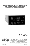
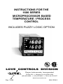
INSTRUCTIONS FOR THE
1600 SERIES
MICROPROCESSOR BASED
TEMPERATURE / PROCESS
CONTROL
INCLUDES FUZZY LOGIC OPTION
LOVE CONTROLS DIVISION
Dwyer Instruments, Incorporated
®
Rev. 10/98
PO Box 338 ❍ Michigan City, IN 46361-0338
(800) 828-4588 ❍ (219) 879-8000 ❍ FAX (219) 872-9057
www.love-controls.com
1
949-1239-3
TABLE OF CONTENTS
GETTING STARTED .............................................................................. 2
INSTALLATION ....................................................................................... 4
DIMENSIONS ......................................................................................... 5
INPUT SELECTION ................................................................................ 5
LOGIC JUMPER SELECTION ................................................................ 6
WIRING ................................................................................................... 7
FRONT PANEL KEY FUNCTIONS ......................................................... 8
NOTATION CONVENTIONS FOR THE MENUS ................................. 10
THE HOME DISPLAY ........................................................................... 10
OPERATION OF SELF TUNE® FUNCTION ........................................ 11
Theory of Operation ..................................................................... 11
Program Setup and Operation .................................................... 12
METHOD FOR SET UP OF A HEAT / COOL CONTROL WITH SELF
TUNE .................................................................................................... 12
PROGRAMMING AND OPERATION FOR RAMP / SOAK FEATURE 13
Theory of Operation ..................................................................... 13
Program Setup .............................................................................. 13
Ramp / Soak Operation ................................................................ 14
MENU SELECTIONS ........................................................................... 15
PRIMARY MENU .................................................................................. 15
SECONDARY MENU ............................................................................ 15
SECURE MENU .................................................................................... 21
DIAGNOSTIC ERROR MESSAGES .................................................... 28
CONFIGURATION MENU .................................................................... 30
SPECIFICATIONS ................................................................................ 35
GETTING STARTED
1.
2.
3.
4.
5.
Install the control as described on page 4.
Make sure that the Input DIP switch is set correctly for the input
you wish to use. Instructions on page 5.
If you wish to use the Logic (5 VDC) output, make sure that the
Logic jumper is in the correct position. See page 6 for details.
Wire your control following the drawing on page 7.
Make any programming changes necessary first in the Secure
Menu (page 21), next in the Secondary Menu (page 15), and
finally in the Primary Menu (page 15). DO NOT make changes to
the Configuration Menu unless specifically instructed. If you need
to back up in a menu, press the INDEX and DOWN ARROW keys
together.
949-1239-3
2
Rev. 10/98
6.
To quickly return to the HOME position, press the UP ARROW
and ENTER keys together, and then the INDEX and DOWN
ARROW keys.
Take the example of a Model 16010 that comes from the factory programmed for type J thermocouples. Suppose for this example you wish to
change the input to 100 ohm Platinum DIN RTD and limit the set point range
between 0° and 500° C.
First, change the input DIP switch as shown on page 5. For RTD inputs
switches 1, 3, and 4 are off, switch 2 is on.
Next, enter the Secure menu as instructed on page 8. Press the INDEX key
until the display shows Inp and press the DOWN ARROW until the display
shows P385. Don't forget to press the ENTER key to retain your setting.
Next, press the INDEX key to display Unit. Press the DOWN ARROW until
the display shows C. Press ENTER.
Next, press the INDEX key until SPL is displayed (pass the dPt and InPt
selections). Press the UP ARROW until the display shows 0. Press
ENTER.
Finally, press INDEX key to display SPH. Press the DOWN ARROW until
the display shows 500. Press ENTER.
The necessary program changes are now complete. After 60 seconds the
display will switch back to the temperature reading. If you want to return
faster, press the UP ARROW and ENTER keys (at the same time) and then
press the DOWN ARROW and INDEX keys ( again at the same time). This
will 'back out' of the menu and immediately display the temperature reading.
If you want to use Self Tune®, Auto/Manual, or the Ramp/Soak Programmer features, see the special sections on these items. Page numbers for
these are in the Contents section on the previous page.
Rev. 10/98
3
949-1239-3
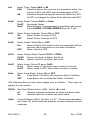
INSTALLATION
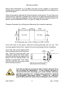
Mount the instrument in a location that will not be subject to excessive
temperature, shock, or vibration. All models are designed for mounting in an
enclosed panel.
Select the position desired for the instrument on the panel. If more than one
instrument is required, maintain the minimum of spacing requirements as
shown on the drawing opposite. Closer spacing will structurally weaken the
panel, and invalidate the IP66, UL type 4 rating of the panel.
Prepare the panel by cutting and deburring the required opening.
45mm
(1.77in)
45mm
(1.77in)
19mm
(0.75in)
Cut Out
45mm
(1.77in)
Cut Out
45mm
(1.77in)
All Tolerances are -0.00 +0.60mm (-0.000 +0.020)
From the front of the panel, slide the housing through the cut out. The
housing gasket should be against the housing flange before installing.
From the rear of the panel slide
the mounting collar over the housing. Hold the housing with one
hand and using the other hand,
push the collar evenly against the
panel until the spring loops are
slightly compressed. The ratchets will hold the mounting collar
and housing in place.
PANEL
10mm (0.25")
MAX.
GASKET
SPRING LOOP
MOUNTING COLLAR (SHOWN IN POSITION)
SLIDE COLLAR ONTO THE HOUSING
BEFORE WIRING THE REAR TERMINALS
It is not necessary to remove the control chassis from
the housing for installation. If the control chassis is
removed from the housing, you must follow industry
standard practice for control and protection against
Electro-Static Discharge (ESD). Failure to exercise
good ESD practices may cause damage to the control.
949-1239-3
4
Rev. 10/98
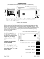
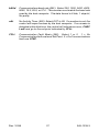
DIMENSIONS
(All dimensions in millimeters with inches in parenthesis.)
125 (4.925)
48 (1.880)
LOVE
114 (4.475)
CONTROLS CORP.
R
SP1
PV
AL
48
(1.880)
SP2
˚F
45
(1.760)
SV
˚C
INDEX
ENTER
AL
AL
R
MADE IN USA
12 (0.450)
* 3 (0.125)
Panel cutout for all models is 45mm x 45mm (1.775 in x 1.775 in).
Allow for 13 mm (0.5 in) clearance at the rear of the instrument.
* Present for SSR outputs.
INPUT SELECTION
Before removing the instrument from its housing, make sure you take
appropriate precautions to avoid electro-static discharge (ESD). See
caution on opposite page. To change the input type, remove the instrument from its housing by grasping the front bezel sides and pulling
forward to release it from
the housing lock.
DIP SWITCH LOCATION
Locate the dip switch on
the right pcb. Determine
the input type desired and
change the dip switch
setting as shown at the
right.
Reinstall the instrument
into the housing.
1 2 3 4
THERMOCOUPLE INPUTS
After changing input selection with the DIP switches,
be sure to change the InP
menu item (page 11) in the
Secure Menu.
RTD INPUTS
CURRENT INPUT
VOLTAGE INPUT
Rev. 10/98
5
949-1239-3
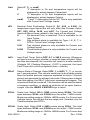
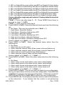
LOGIC JUMPER SELECTION
Instruments with SSR or RELAY type outputs can be changed to and from a
LOGIC output in the field.
CAUTION: Damage to the instrument may result from an
incorrectly installed jumper strip. Follow the instructions
carefully. Damage to the instrument may also result from
improper handling. Use appropriate precautions to avoid
Electro-Static Discharge (ESD).
1.
2.
3.
4.
Remove the instrument from its housing. Grasp the front bezel sides and
pull forward to release it from the housing lock.
Locate the desired logic jumper strip on the left printed circuit board. The
OUTPUT A jumper
OUTPUT A SET FOR LOGIC TYPE OUTPUT
strip is always located near the top
edge
To remove the logic
jumper strip, carefully
insert a small flat
blade screwdriver between the retaining
clip and the jumper
OUTPUT B SET FOR SSR or RELAY TYPE OUTPUT
at one end of the
SLIGHT PRESSURE TO RELEASE
jumper strip. Apply slight pressure to
RETAINING CLIP
move the clip away from the jumper end
until it is released, then lift it up and out of
the clip.
To re-install the jumper strip, hold it with the spring contacts in the desired
position. Face springs up for SSR or RELAY outputs, or face springs down
for LOGIC outputs. Insert one end of the jumper strip under the retaining
clip and press the other end down until the remaining clip engages the
jumper.
SPRINGS DOWN
SPRINGS UP
INSTALLING JUMPER FOR
LOGIC TYPE OUTPUT
INSTALLING JUMPER FOR
SSR or RELAY TYPE
OUTPUT
5.
6.
To avoid any damage, recheck the jumper installation and the housing rear
terminal panel output wiring.
Replace the instrument into its housing.
949-1239-3
6
Rev. 10/98
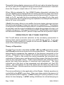
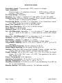
OPTIONS
Thermocouple
Current
Voltage
INPUTS
RTD*
Rev. 10/98
WIRING
+
+
-
-
Relay**
N.O.
}{
}{
ALARM OUTPUT
7
Terminals 4 & 5 are
Normally Open. See
Rating Label.
F1
3/8 A @250 VAC
Medium Lag
Solid State Relay
N.O.
AL1
F1
Line Input See Rating
Label for details
* For 2-wire 1000 Ω RTD use terminals 1 & 3.
For 2-wire 100 Ω RTD use terminals 1 & 3, and
place a jumper wire between terminals 3 & 4.
5VDC Output
5V = On, 0V = Off
5VDC @
25mA
5VDC @
25mA
SSR Derating Chart
˚C
˚F
CURRENT
25
77
3.50
35
95
2.75
45
113
2.00
55
131
1.25
948
Current or
Voltage
-
+
+
-
-
+
+
-
}{
}{
Output
A
Output
B
+
936
0 to 10 VDC @ 25 mA
For Relay or SSR
outputs use type MDA or
3AB 3.5A medium lag
fuse.
-
** R/C snubber is
recommended for driving
solenoid or contactor
loads.
B (+)
INPUT WIRING: Do not run thermocouple of other signal wiring in the same conduit as power
leads. Use only the type of thermocouple or RTD probe for which the instrument has been
programmed. See Secure Menu for Input Programming.
949-1239-3
For thermocouple input always use extension leads of the same type designated for your
thermocouple.
Outputs A and B may be logically swiched. See Secure Menu for details.
992
A (-)
FRONT PANEL KEY FUNCTIONS
Set Point 1 Lamp
Process Variable
Alarm Lamp
Set Point 2 Lamp
Set Variable
°F Indicator
°C Indicator
INDEX: Pressing the INDEX key advances the display to the
next menu item. May also be used in conjunction with other
keys as noted below.
UP ARROW: Increments a value, changes a menu item, or
selects the item to ON in the upper display.
DOWN ARROW: Decrements a value, changes a menu
item, or selects the item to OFF in the upper display.
ENTER: Pressing ENTER stores the value or the item
changed. If not pressed, the previously stored value or item will
be retained.
UP ARROW & ENTER: Pressing these keys simultaneously brings up the
secondary menu starting at the auto/manual selection. Pressing these
keys for 5 seconds will bring up the secure menu.
INDEX & DOWN ARROW: Pressing these keys simultaneously will allow
backing up one menu item, or if at the first menu item they will cause the
display to return to the primary menu. If an alarm condition has occurred,
these keys may be used to reset the alarm.
INDEX & ENTER: Pressing these keys simultaneously and holding them
for 5 seconds allows recovery from the various error messages. The
following menu items will be reset:
LPbr: Loop break
SEnC: Sensor rate of change
ALiH: Alarm inhibit
OPEn InP: Open input error message
ArEA: Area error message
bAd InP: Bad input error message
CHEC CAL: Check calibration error message
Correct the problems associated with the above conditions first before
using these reset keys. More than one error could be present. Caution is
advised since several items are reset at one time.
949-1239-3
8
Rev. 10/98
While in the Primary or Secondary menu, if no key is pressed for a period
of 30 seconds, the display will return to the HOME position displaying the PV
and SV values. The time is increased to 1 minute when in the Secure menu.
NOTE: To move to the primary menu quickly from any other menu, press
the UP ARROW & ENTER keys followed by pressing the INDEX & DOWN
ARROW keys.
NOTE: Program the Secure Menu first, the Secondary Menu second,
and the Primary Menu last.
SECURITY LEVEL SELECTION
Four levels of security are provided. The display shows the current security
level. To change security levels change the password value using the UP &
DOWN ARROW keys and pressing the ENTER key. Refer to the password
table below for the correct value to enter for the security level desired. The
SECr menu item security level may be viewed or changed at any time
regardless of the present security level. The password values shown in the
table cannot be altered, so retain a copy of this page for future reference.
This will be the only reference made to password values in this instruction
book.
PASSWORD TABLE
MENU
SECURITY LEVEL
SECURITY
DISPLAYED VALUE
WHEN VIEWED
PASSWORD
VALUE TO ENTER
Primary
Secondary
Secure
Locked
Locked
Locked
1
1110
Primary
Secondary
Secure
Unlocked
Locked
Locked
2
1101
Primary
Secondary
Secure
Unlocked
Unlocked
Locked
3
1011
Primary
Secondary
Secure
Unlocked
Unlocked
Unlocked
4
111
Rev. 10/98
9
949-1239-3
NOTATION CONVENTIONS FOR THE MENUS
Because of the number of features available in this control, information is
included that may not apply to your specific control. All usable features are
included in this book, but may not be used in your process. To increase
clarity the following conventions are used:
1. Certain features, Menu Items, and functions shown in this book may or
may not appear on your control, depending on other Menu Item selections.
At various places in the Menus there are notes identifying Menu Items that
"control" or "direct" other menu items. If you are looking for a particular
menu item and can't find it, check the menu item that is its "control" for
proper setting.
2. The "#" symbol is used in two ways. It is used inside a group of
characters to indicate which set point function (SP1 or SP2) is being
affected. It is also used before a group of characters of a menu item to
indicate that there may be more than one selection or value for that menu
item.
3. Features that apply only to Options will be printed in Italics.
THE HOME DISPLAY
The home display is the normal display while the control is operating. If no
errors or functions are active, the HOME display will indicate the Process
Variable (the temperature, pressure, flow, RH, etc., that is being measured)
on the top display and the Set Variable (Set Point 1) on the bottom.
Items that can change the HOME display are the Auto/Manual function, the
Prog function, the PctO function, and any error message. Description of
these special displays follow.
If Auto/Manual Menu Item is On, the home display is changed. The upper
display continues to show the Process Variable (PV), but the lower display
changes to show the percentage of output in tenths of a percent to 99.9%
(0.0 to 99.9), or 100 if 100%. The display digit to the right of the number
shows a flashing letter o to indicate that the value displayed is no longer the
SV, but percent output. The SP2 output is indicated by the use of an
overline on the letter õ. Access to the SP2 value is done by the INDEX key.
See Auto/Manual Operation on Page 13 for further information.
If Prog is turned On, the HOME display changes the SV display from SP1
to the Present Set Variable as calculated by the Ramp/Soak Programmer
function. When Prog is On the StAt Menu Item changes the hHOME display
firther. When StAt is selected OFF, the HOME display alternately indicates
the normal HOME and the Ramp/Soak partial status in the Lower Display.
949-1239-3
10
Rev. 10/98
The partial status display sequences with the set value showing the ramp
(S1rA) or soak (S1So) segment being processed at that moment. It will also
show the Program output status if at Hold or OoFF.
When StAt is selected On, the HOME Display alternately indicates the
normal HOME and the Ramp/Soak full status in both the upper and lower
displays. The full status display sequences with the set value; Program run,
Hold, or OoFF; and with the time remaining for the ramp S1rA or the soak
S1So segments.See Programming and Operation for Ramp/Soak Feature
below for more information.
If PctO (Secondary Menu) is turned On, the lower display changes to show
the active percentage of output as required to maintain SP1. The display
is similar to the Auto/Manual display above, except that the letter indicators
do not flash, and the output is displayed in whole percentages of output, not
in tenths of a percent. If the control has both SP1 and SP2, the lower display
will alternate between the SP1 percent output and the SP2 percent output.
OPERATION OF SELF TUNE® FUNCTION
Self Tune® allows automatic selection of the necessary parameters to
achieve best control operation from your 1600 Series control. If you are
using the control output as a simple on-off function (S#Ot set for OnOF),
none of the following will apply.
Theory of Operation
The Self Tune function calculates the Pb1, rES, and rtE parameters under
the PID tunE selection as shown in the Secondary Menu . These values are
determined by measuring the response of the process connected to the
control. When Self Tune is started, the control temporarily acts as an onoff control. While in this mode the control measures the overshoot and
undershoot of the process, and the period of the process (the time from peak
value to the next peak value). These measurements are collected over a
period that lasts three periods of overshoot and undershoot. The data
collected over this time is then compared and calculated into final PID
values. The calculations for the PID values are the same as used in the
standard Ziegler - Nichols equations that have been recognized as standard
for decades.
The only modification to the application of the Ziegler - Nichols equations is
controlled by the dFAC menu item. This menu item controls the amount of
rate (derivative) that is applied. A dFAC setting of 3 (factory default) or less
allows for less damping. A dFAC setting of 4 allows for critical damping as
Rev. 10/98
11
949-1239-3
set forth in Ziegler - Nichols. A dFAC setting of 5 or more allows over
damping of the process.
Program Setup and Operation
In the secondary menu set tunE to SELF. Skip LErn and check to make
sure that dFAC is set to the desired value. Back up to LErn and set to YES.
The control will begin the Self Tune function. While the Self Tune function
is active, the right hand decimal point on the lower display will blink. When
Self Tune is complete, the blinking will stop.
After the initial Self Tune is complete, the instrument will look at the LErn
menu item to determine if you wish to have the process continually tuned.
Setting LErn to Cont will allow the control to periodically check the tuning
parameters. If you wish to have the tuning values locked in, set Lern to End.
If you wish at any time to view the PID values, change the tunE setting to
PID. This allows examination and / or modification of the values calculated.
We recommend that you do not change the calculated values unless you
have a firm understanding of the parameters involved and their function. For
more information on PID tuning, please contact your supplier.
METHOD FOR SET UP OF A HEAT / COOL CONTROL WITH SELF
TUNE
Determine if the process is predominantly heating or cooling. An extruder,
for example, is predominantly cooling when running product. An environmental chamber can be either heating or cooling.
If the process is predominantly cooling, set S1St to dir and S2St to rE. If the
process is predominantly heating, set S1St to rE and S2St to dir. Redirect
SP1 to output A or B as required by the hardware (see SP1o). Set S2t to
dE. Set SP2 for zero (no overlap of bands, no deadband). Set Pb2 to a
desired value (default is 12° F). Set tunE to SELF, Strt to YES, and LErn
to End.
Start the process and wait for it to come to stability. Occasionally check that
the Self Tune has completed the learning process by INDEXing to Strt in the
secondary menu. If the YES value has changed to no, then the process has
been learned. Once learning is complete, you may adjust SP2 to either
overlap the SP1 band (SP2 value less than zero), or add some separation
(or dead band) between them (SP2 greater than zero). Adjust SP2 as
required to optimize control.
949-1239-3
12
Rev. 10/98
PROGRAMMING AND OPERATION
FOR RAMP / SOAK FEATURE
The ramp / soak feature offers a great deal of flexibility by allowing changes
in the set point to be made over a predetermined period of time.
Theory of Operation
The 1600 Series controls offer a very simple approach to programming a
ramp. Rather than requiring the operator to calculate an approach rate
(usually in degrees per minute), the 1600 does the calculation internally.
Thus, the operator only needs to program the target set point, the time
desired to reach that point, and the time desired to hold at that point. When
the ramp segment is executed by the control, it calculates the ramp required
to move the process from the starting value (current PV) to the desired
value (programmed SP) in the time allowed.
Care must be taken, however, that the process does actually reach the
soak value before the soak time starts. Make sure to test any program for
desired results before running production material.
Do not operate Self Tune while a ramp function is operating. The
ramp function will prevent the Self Tune from operating properly.
Make sure that all tuning is set up before operating Ramp / Soak.
Program Setup
The programming for the Ramp / Soak function is done in the Secondary
Menu.
In the Secondary Menu INDEX to Prog and make sure that Prog is set to
OFF.
Skip the StAt setting (this is discussed later) and press INDEX to 1rt.
Set 1rt to the amount of time you want for the ramp. This value is in time
units from 00.01 to 99.59 (hh,mm). Press INDEX.
Set 1St to the amount of time you want for the soak. This value is in time
units from 00.01 to 99.59 (hh,mm). Press INDEX.
The last menu item for the ramp / soak function is PEnd. PEnd determines
what the control does when the program has ended. You may choose to
Hold the set point (SP1), or turn the outputs off (OoFF).
Rev. 10/98
13
949-1239-3
Ramp / Soak Operation
When you wish to start the program, enter the Secondary Menu and set the
Prog menu item to On. Return to the HOME position by waiting for the
display to time out or by pressing the UP ARROW / ENTER keys and then
the DOWN ARROW / INDEX keys.
Changing the AUTO / MANUAL menu item to Auto OFF will also suspend
the program operation. This also puts the control into manual mode.
Auto / Manual Control
Manual Control is enabled through the Secondary Menu. When Auto is
turned On, the lower display in the HOME position will display the output in
percent for SP1 or SP2, and is adjustable for each from 0.0 to 100 percent.
SP1 appears first with a flashing “o” on the right hand corner of the lower
display to represent percent. Press INDEX to display SP2 output. A
flashing "õ" will appear on the right hand corner of the lower display to
represent percent.
When Manual is enabled, the present control outputs are held (bumpless
transfer) and displayed. The output for SP1 or SP2 can then be manually
adjusted while displayed by pressing the UP ARROW or DOWN ARROW
key to change the value, and then the ENTER key to activate.
The Upper display will normally indicate the Process Value. Since Manual
will override most fault messages the upper display could indicate a fault
message. Refer to the Diagnostic Error Message Section for further
explanation.
949-1239-3
14
Rev. 10/98
MENU SELECTIONS
PRIMARY MENU
Press INDEX to scan the Lower Display. Press UP ARROW or DOWN
ARROW to change the value in the upper display.
In the following the symbol "#" will be used before a letter to indicate the set
point value to be viewed and/or modified. (Applies to Option 948 only.)
#SP1
SP1
(948) or
Set Point 1, Main Control Point.
SP2
Set Point 2, if equipped.
SECONDARY MENU
Hold UP ARROW & ENTER. Press INDEX to scan the Lower Display.
Press UP ARROW or DOWN ARROW to change the value in the upper
display.
Auto
Auto/Manual Control: Select On or OFF.
On
Automatic Control
OFF
Manual Control is enabled. The lower display in the
HOME position will display the output in percent for SP1
or SP2, and is adjustable for each from 0.0 to 100
percent. SP1 appears first with a flashing “o” on the right
hand corner of the lower display to represent percent.
Press INDEX to display SP2 output. A flashing "õ" will
appear on the right hand corner of the lower display to
represent percent. When Manual is enabled, the present
control outputs are held (bumpless transfer) and displayed. The output for SP1 or SP2 can then be manually
adjusted while displayed by pressing the UP or DOWN
Arrow key to change the value, and then the ENTER
key. The Upper display will normally indicate the Process Value. Since Manual will override most fault messages the upper display could indicate a fault message.
Refer to the Diagnostic Error Message Section for
further explanation.
ALLo
Pt.
Alarm Low: The Low Alarm point is usually set below the Main Set
ALHi
Alarm High: The High Alarm Point is usually set above the Main
Set Pt.
Rev. 10/98
15
949-1239-3
SP
Active set point (948): Select 1SP1, 2SP1, 3SP1, or 4SP1. Allows
setting of the multiple stages of SP1, and SP1 tuning constants.
#SP1
Set Point Value # (948): Select desired value.
#tun
tunE
(948) or
Tuning Choice: Select SELF, Pid, SLO, nor, or FASt.
SELF
The Controller will evaluate the Process and select the
PID values to maintain good control. Active for SP1
only.
Strt
Select YES or no
YES
Start Learning the Process. After the
process has been learned the menu
item will revert to no.
no
Learning will stay in present mode.
LErn Select Cont or End
Cont
Continuously adjust the PID values to
maintain the best control. The Process is being monitored at all times by
collecting and analyzing the data to
adjust the PID values. (adaptive control).
End
The Process data is collected once
and then the PID values are saved,
tuning is stopped.
dFAC Damping factor, Select OFF, 1 to 7. Sets the
ratio of Rate to Reset for the SELF tunE mode.
7 = most Rate. Factory set to 3. For a fast
response process the value should be lowered
(less Rate). For a slower process the value
should be increased (more Rate).
Pid
Manually adjust the PID values. PID control consists of
three basic parameters, Proportional Band (Gain), Reset Time (Integral), and Rate Time (Derivative).
#Pb1 (948) or
Pb1
Proportional Band (Bandwidth). Select 6 to
5000 °F, 3 to 2778 °C, or 6 to 9999 counts.
Pb2
Proportional Band (Bandwidth). Select 6 to
5000 °F, 3 to 2778 °C, or 6 to 9999 counts.
(Appears after #rtE when Option 948 is selected.)
#rES (948) or
rES
Automatic Reset Time. Select OFF, 0.1 to 99.9
minutes. Select OFF to switch to OFS.
#OFS (948) or
949-1239-3
16
Rev. 10/98
OFS
SLO
nor
FASt
Manual Offset Correction Select OFF, 0.1 to
99.9%. Select OFF to switch to rES.
#rtE
(948) or
rtE
Rate Time. Select OFF, 0.01 to 99.99 minutes,
Derivative.
PID values are preset for a slow response process.
PID values are preset for a normal response process.
PID values are preset for a fast response process.
Pid2
Linkage of PID parameters between SP1 and SP2: Select On or
OFF.
On
Links SP2 to SP1 or #SP1 rEs and rtE terms for heat/
cool applications.
OFF
Sp2 functions without rEs and rtE.
ArUP
Anti- Reset Wind-up Feature: Select On or OFF.
On
When ArUP is On the accumulated Reset Offset value
will be cleared to 0% when the process input is not within
the Proportional Band.
OFF
When ArUP is OFF, the accumulated Reset Offset
Value is retained in memory when the process input is
not within the Proportional Band.
ArtE
Approach Rate Time: Select OFF, 0.01 to 99.99 minutes. The
function defines the amount of Rate applied when the input is
outside of the Proportional Band. The ArtE time and the rtE
time are independent and have no effect on each other. To
increase damping effect and reduce overshoot set the approach
rate time for a value greater than the natural rise time of the
process (natural rise time = process value time to set point).
Fint
Fuzzy Logic Intensity(942): Select 0 to 100%. 0% is OFF
(disables Fuzzy Logic). The function defines the amount of
impact Fuzzy Logic will have on the output.
Fbnd
Fuzzy Logic Error Band(942): Select 0 to 4000 °F, 0 to 2222°C,
or 0 to 4000 counts. Sets the bandwidth of the Fuzzy Logic. Set
Fbnd equal to PID proportional band (Pb1) for best results.
FrtE
Fuzzy Logic Rate of Change(942): Select 0.00 to 99.99°F/sec.,
0.00 to 55.55°C/sec., or 0.00 to 99.99 counts/sec. For best initial
setting, find the degree/sec change of process value near set
point 1 with output ON 100%. Multiply this value by 3. Set FrtE
to this calculated value.
Rev. 10/98
17
949-1239-3
PEA
Peak and Valley feature will remember the Highest (PEA) and
lowest (VAL) Input the Instrument has had since the last reset or
Power On. At Power On they are reset to the present input, and
VAL therefore may have to be manually reset. To manually reset
the value, PEA or VAL must be in the lower display and then press
the ENTER key. This will cause the Item to be reset to the present
input value.
In the following the symbol "#" will be used following letters to refer to either
a number "1" or number "2". The "1" will relate to SP1 functions, the "2" for
SP2. If your control is not equipped with a second set point, no SP2
functions will appear. The appearance of CY#, SP#d, or PUL# is
dependent upon the output type selected in the Secure Menu item S#Ot.
If time proportioning (cycle time) was selected, then CY# is adjustable. If
On - Off was selected, then SP#d is adjustable. If pulsed time proportioning
was selected then PUL# is adjustable. If none of the above are selected
the menu indexes directly to S#Ot.
Cycle Rate: Select 2 to 80 sec. Time Proportioning Control is
adjustable in 2 sec. steps. For best contact life, a time should be
selected as long as possible without causing the process to
wander.
SP#d
Set Point On-Off Differential. Select 1 to 1999 deg. or counts.
When adjusting SP#d keep in mind that SPL and SPH have to be
considered to avoid a CHEC error message.
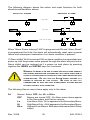
Pulsed Time Proportioning Output: Select 1 to 7. 1 = Linear and
7 = most non-linear. Changes output linearty for use in cooling
applications or for an extremely fast response processes. At the
OUTPUT
PUL#
OUTPUT
CY#
DIRECT ACTING (S#St = dir)
(UPSCALE DIFFERENTIAL)
0
DIFF.
(SP#d)
INPUT
REVERSE ACTING (S#St = rE)
(DOWNSCALE DIFFERENTIAL)
0
SP# (DISPLAYED VALUE)
DIFF.
(SP#d)
INPUT
SP# (DISPLAYED VALUE)
center of the proportional band, a pulse value of 1 provides an
output of one second on and one second off (50% output). A pulse
value of 2 provides an output of one second on and two seconds
off (33% output). Output at center of band equals one second on,
2(pulse value-1) seconds off.
949-1239-3
18
Rev. 10/98
S#Ot
PctO
Set Point Output Type. FT, Curr, or Volt.
Ft
refers to Fast Time Proportioning, for Solid State Relay
or 5V Logic Outputs. Timing is fixed at 1 sec.
Curr
refers to Proportional Current Output of 0 to 20 mA.
Volt
refers to Proportional Voltage Output of 0 to 10 V.
Both Curr & Volt are selected by the Hardware Configuration Code and cannot be changed.
Percent Output Feature: Select On or OFF.
On
When selected On, the HOME lower display will indicate the output of the controller in percent. An “o” will
appear in the right hand side of the lower display to
indicate percent output for SP1. An "õ" will appear on
the right hand corner of the lower display to represent
percent output for SP2. The display will alternate
between these values.
OFF
Percent Output display is disabled.
Prog
Ramp/Soak Feature: Select On or OFF
StAt
Status Display in the HOME Position when Prog (above) is On:
Select On or OFF. When selected OFF, the HOME display will
alternately indicate the normal HOME and the Ramp/Soak partial
status in the Lower Display. The partial status display sequences
with the set value showing the ramp (S1rA) or soak (S1So)
segment being processed at that moment. It will also show the
Program output status if at Hold or OoFF.
When selected On, the HOME Display will alternately indicate the
normal HOME and the Ramp/Soak full status in both the upper
and lower displays. The full status display sequences with the set
value; Program run, Hold, or OoFF; and with the time remaining
for the ramp S1rA or the soak S1So segments.
1rt
Ramp Time in Hours & Minutes: Select 0.00 to 99.59 (HH.MM).
1St
Soak Time in Hours & Minutes: Select 0.00 to 99.59 (HH.MM).
PEnd
End of Soak action: Select Hold or OoFF.
Hold
Stay at the Present Set Pt.
OoFF
Turn Off SP1 and SP2 Outputs at the End of the Soak.
InPC
Input Correction: Select ±500 °F (±260 °C) or ±1000 counts. This
feature allows the input value to be changed to agree with an
external reference or to compensate for sensor error. When
setting values having one or more decimal points, the lowest
negative value allowed is -199.9, -19.99, or -1.999. Note: InPC
Rev. 10/98
19
949-1239-3
is reset to zero when the input type is changed, or when decimal
position is changed in T/C or RTD ranges. Changing decimal
position in current or voltage ranges will not reset InPC.
FiLt
Digital Filter: Select OFF, 1 to 99. In some cases the time constant
of the sensor, or noise could cause the display to jump enough
to be unreadable. A setting of 2 is usually sufficient to provide
enough filtering for most cases, (2 represents approximately a 1
second time constant). When the 0.1 degree resolution is selected this should be increased to 4. If this value is set too high,
controllability will suffer.
LPbr
Loop Break Protection: Select OFF, 1 to 9999 seconds. If, during
operation, the output is minimum (0%) or maximum (100%), and
the input moves less than 5°F (3°C) or 5 counts over the time set
for LPbr, the LOOP bAd message will appear. This condition can
also be routed to an Alarm Condition if alarms are present and
turned On (see ALbr in the secure menu). The loop break error can
be reset by pressing the ENTER key when at the LPbr menu item.
The INDEX & ENTER keys may also be used.
POL
Process Output Low (936): Select -450°F, -260°C, or -1999
counts to 50 degrees or counts less than POH.
POH
Process Output High (936): Select from 50 degrees or counts
greater than POL to +9990°F, +5530°C, or 9990 counts. A
voltage output is scalable from 0 to 10 VDC that represents the
Process Variable. To properly scale the output, the values for
POL and POH must be calculated. The simplest example is an
output of 0 to 10 VDC from 0 to 200°. In this example POL=0 and
POH=200. To Calculate POL and POH for other ranges use the
following:
K = (Highest desired temperature - Lowest desired temperature)
/ (Maximum desired voltage - Minimum desired voltage)
POH = ((10 - Maximum desired voltage) * K) + Highest desired
temperature
POL = ((Minimum desired voltage - 0) * K) - Lowest desired
temperature
LOrE
Local / Remote Status (992): Select LOC or rE.
LOC
Write commands from the host computer are rejected.
rE
Write commands from the host computer are accepted. The
control will also look to the No Activity Timer (nAt) setting to
see if regular host computer commands are required. See
nAt and CFLt (Page 27) for additional information.
949-1239-3
20
Rev. 10/98
CFSP
Communications Fail Set Point (992): Set to desired value.
Addr
Control Address (992): Set from 1 to FF. This number (hexadecimal, base 16) must match the address number used by the host
computer. Viewed only in this menu.
SECURE MENU
Hold UP ARROW & ENTER for 5 Seconds. Press INDEX to change the
lower display. Press UP ARROW or DOWN ARROW to change the value
in the upper display.
SECr
Security Code: See the Security Level Selection and the Password Table in this manual, in order to enter the correct password.
InP
Input Type: Select one of the following. The Inputs are based on
four different groups; Thermocouples, RTD’s, Current, and Voltage. If changing from one of these groups, the DIP switch on the
A/D circuit board will have to be changed to match that particular
group. Refer to the Input wiring section for the proper switch
settings.
J-IC Type “J” Thermocouple
CA
Type “K” Thermocouple
EType “E” Thermocouple
tType “T” Thermocouple
LType “L” Thermocouple
nType “N” Thermocouple
r-13 Type “R” Thermocouple
S-10 Type “S” Thermocouple
bType “B” Thermocouple
CType “C” Thermocouple
P392 100 ohm Platinum (NIST 0.00392 Ω/Ω/°C), Love
Cal. 104.
n120 120 ohm Nickel, Love Cal. 105.
P385 100 ohm Platinum (DIN 0.00385 Ω/Ω/°C), Love Cal.
106.
Curr DC Current Input 0.0 to 20.0 or 4.0 to 20.0 milliamperes.
UoLt DC Voltage Input 0.0 to 5.0 or 1.0 to 5.0 volts.
- - - - Reserved
OSUP
Zero Suppression: Select On or OFF. Only with Current and
Voltage input types.
OFF The input range will start at 0 (zero) Input.
On
The input range will start at 4.00 mA or 1.00 V.
Rev. 10/98
21
949-1239-3
Unit
Select F, C, or nonE.
F
°F descriptor is On and temperature inputs will be
displayed in actual degrees Fahrenheit.
C
°C descriptor is On and temperature inputs will be
displayed in actual degrees Celsius.
nonE
°F and °C descriptors will be Off. This is only available
with Current and Voltage Inputs.
dPt
Decimal Point Positioning: Select 0, 0.0, 0.00, or 0.000. On
temperature type inputs this will only effect the Process Value,
SP1, SP2, ALLo, ALHi, and InPC. For Current and Voltage
Inputs all Menu Items related to the Input will be affected.
0
No decimal Point is selected. This is available for all
Input Types.
0.0
One decimal place is available for Type J, K, E, T, L,
RTD’s, Current and Voltage Inputs.
0.00
Two decimal places is only available for Current and
Voltage Inputs.
0.000
Three decimal places is only available for Current and
Voltage inputs.
InPt
Input Fault Timer: Select OFF, 0.1 to 540.0 minutes. Whenever
an Input is out of range, shorted, or open the timer will start. When
the time has elapsed, the controller will revert to a safe condition
(Outputs Off, Flashing Displays). If OFF is selected, the Input
Fault Timer will not be recognized (time = infinite).
SEnC
Sensor Rate of Change: Select OFF, 1 to 4000 °F, °C, or counts
per 1 second period. This value is usually set to be slightly greater
than the fastest process response expected during a 1 second
period, but measured for at least 2 seconds. If the process is faster
than this setting, the SEnC bAd error message will appear. The
outputs will then be turned off. This function can be used to detect
a runaway condition, or speed up detection of an open thermocouple. Use the INDEX & ENTER keys to reset.
SCAL
Scale Low: Select 100 to 9999 counts below SCAH. The total
span between SCAL and SCAH must be within 11998 counts.
Maximum setting range is -1999 to +9999 counts. For Current and
Voltage inputs, this will set the low range end. Viewable only for
Thermocouples and RTD’s.
SCAH
Scale High: Select 100 to 9999 counts above SCAL. The total
span between SCAL and SCAH must be within 11998 counts.
Maximum setting range is -1999 to +9999 counts. For Current and
949-1239-3
22
Rev. 10/98
Voltage inputs, this will set the high range end. Viewable only for
Thermocouples and RTD’s.
SPL
Set Point Low: Select from SCAL value to SPH value. This will set
the minimum SP1,SP2, ALLo, ALHi, SP1d, and SP2d values that
can be entered. If any of the values are less than the SPL value,
a check message will appear and the value will not be accepted.
SPH
Set Point High: Select from SCAH value to SPL value. This will set
the maximum SP1, SP2, ALLo, ALHi, SP1d, and SP2d values that
can be entered. If any of the values are greater than the SPH
value, a check message will appear and the value will not be
accepted.
SP1o
Set Point 1 Output Terminal Assignment: Select OutA or Outb.
NOTE: Reassigning the output terminals does not change the
Hardware type assigned to those terminals. For single set point
models, SP1o is locked to OUT A.
OutA
Set Pt. 1 output will be directed to terminals 7 & 8 and
Set Pt. 2 output to terminals 9 & 10.
Outb
Set Pt. 1 output will be directed to terminals 9 & 10 and
Set Pt. 2 output to terminals 7 &8.
S#Ot
Set Point Output Type: Select CY, OnOF, PUL, or Ft. Fixed for
Curr and Volt, the Hardware Configuration has selected this.
CY
Cycle Rate, Adjustable Time Proportioning.
CY#
Cycle Rate Time: Select 2 to 80 sec.
OnOF On/Off Output.
SP#d Set Point Differential in 1 degree or count steps
from 2 degrees or counts to full scale, but
limited by SPL and SPH.
PUL
Pulse Time Proportioning.
PUL# Pulse Width Value: Select 1 to 7.
Ft
Fast Time Proportioning: Fixed at 1 sec. Time Base.
Volt
Proportional Voltage, 0 to10 V.
Curr
Proportional Current, 0 to 20 mA.
S#St
Set Point State: Select dir or rE.
dir
Direct Action. As the input increases the output will
increase. Most commonly used in cooling processes.
rE
Reverse Action. As the input increases the output will
decrease. Most commonly used in heating processes.
Rev. 10/98
23
949-1239-3
S#OL
Set Point Output Low Limit: Select 0 to 90% but less than S#OH.
This item limits the lowest output value. This is useful for adding
a bias to the process when needed. When a current or voltage
output is used, the standard output value is 0 to 20mA or 0 to 10V.
If 4 to 20 mA or 2 to 10 V is required, the S#OL value should be
set for 20% to raise the lowest output.
S#OH
Set Point Output High Limit: Select 10 to 102% but greater than
S#OL. This item allows setting the maximum output limit. This is
useful with processes that are over powered.
S#LP
Set Point Lamp: Select O on or OoFF.
O on
Lamp ON when Output is ON.
OoFF
Lamp OFF when Output is ON.
S2t
Set Point 2 type: Select AbS or dE.
AbS
Absolute SP2. SP2 is independent of SP1, and may be
set anywhere between the limits of SPL and SPH.
dE
Deviation SP2. SP2 is set as a deviation from SP1, and
allows SP2 to retain its relationship with SP1 when SP1
is changed (tracking SP2).
ALARM TYPE AND ACTION
Caution: In any critical application where failure could
cause expensive product loss or endanger personal
safety, a redundant limit controller is recommended.
When setting an alarm value for an absolute alarm (ALt = AbS), simply set
the value at which the alarm is to occur.
When setting the alarm value for a deviation alarm ( ALt = dE), set the
difference in value from the Set Value (SV) desired. For example if a low
alarm is required to be 5 degrees below the SV, then set ALLo to -5. If a high
alarm is required 20 degrees above the SV, then set ALHi to +20. If SP1
is changed, the alarm will continue to hold the same relationship as
originally set.
949-1239-3
24
Rev. 10/98
The following diagram shows the action and reset functions for both
absolute and deviation alarms.
ABSOLUTE ALARMS
DEVIATION ALARMS
ALHi
High Alarm
ALHi
OFF
SP1
OFF
ON
ON
D
D
ALLo
Low Alarm
ALLo
SP1
ON
OFF
ON
D
OFF
D
ALLo
ALHi
High and Low Alarm
ALLo
ON
ALHi
OFF
D
OFF
SP1
ON
ON
D
OFF
D
OFF
ON
D
When “Alarm Power Interrupt” ALPi is programmed ON and “Alarm Reset”
is programmed for Hold, the alarm will automatically reset upon a power
failure and subsequent restoration if no alarm condition is present.
If “Alarm Inhibit” ALiH is selected ON, an alarm condition is suspended upon
power up until the process value passes through the alarm set point once.
Alarm inhibit can be restored as if a power up took place by pressing
together the INDEX and ENTER keys for 5 seconds.
WARNING: IF INHIBIT IS ON AND A POWER FAILURE OCCURS DURING A
HIGH ALARM, RESTORATION OF POWER WILL NOT CAUSE THE ALARM TO
OCCUR IF THE PROCESS VALUE DOES NOT FIRST DROP BELOW THE HIGH
ALARM SETTING.
DO
NOT USE THE
ALARM INHIBIT
BE SURE
HAZARD IS CREATED BY THIS ACTION.
FEATURE IF A
TO TEST ALL
COMBINATIONS OF HIGH AND LOW ALARM INHIBIT ACTIONS BEFORE
PLACING CONTROL INTO OPERATION.
The following Secure menu items apply only to the alarm.
AL
Alarms: Select OFF, Lo, Hi, or HiLo.
OFF
Alarms are turned OFF. No Alarm menu items appear
in the Secondary and Secure menus.
Lo
Low Alarm Only. ALLo appears in the Secondary Menu.
Hi
High Alarm Only. ALHi appears in the Secondary Menu.
HiLo
High and Low Alarms. Both share the same Alarm Relay
output.
Rev. 10/98
25
949-1239-3
ALt
Alarm Type: Select AbS or dE
AbS
Absolute Alarm that may be set anywhere within the
values of SPL and SPH and is independent of SP1.
dE
Deviation Alarm that may be set as an offset from SP1.
As SP1 is changed the Alarm Point will track with SP1.
ALrE
Alarm Reset: Select OnOF or Hold.
OnOF Automatic Reset.
Hold
Manual Reset. Acknowledge by simultaneously pressing the INDEX & DOWN ARROW keys for 5 sec.
ALPi
Alarm Power Interrupt: Select On or OFF.
On
Alarm Power Interrupt is ON.
OFF
Alarm Power Interrupt is OFF.
ALiH
Alarm Inhibit: Select On or OFF.
On
Alarm Inhibit is ON. Alarm action is suspended until the
process value first enters a non-alarm condition.
OFF
Alarm Inhibit is OFF.
ALSt
Alarm Output State: Select CLOS or OPEn.
CLOS Closes Contacts at Alarm Set Point.
OPEn
Opens Contacts at Alarm Set Point.
ALLP
Alarm Lamp: Select O on or OoFF.
O on
Alarm Lamp is ON when alarm contact is closed.
OoFF
Alarm Lamp is OFF when alarm contact is closed.
ALbr
Alarm Loop Break: Select On or OFF.
On
Loop Break Condition will cause an Alarm Condition.
OFF
Loop Break will not affect the Alarm Condition.
The following Secure menu items apply only to Options. They may not
appear in your control.
SPSA
Set Point Select Action (948): Select rE or Int.
rE
Remote (external) selection of active set point value.
Int
Internal selective of active set point value.
Addr
Control Address (992): Set from 1 to FF. This number (hexadecimal, base 16) must match the address number used by the host
computer.
949-1239-3
26
Rev. 10/98
bAUd
Communications baud rate (992): Select 300, 1200, 2400, 4800,
9600, 19.2, 28.8, or 57.6. This number must match the baud rate
used by the host computer. The data format is 8 bits, 1 stop bit,
No parity.
nAt
No Activity Timer (992): Select OFF to 99. If a number is set, the
control will expect access by the host computer. If no access is
detected within that time, the control will indicate an error, CHEC
LorE and go to the set point indicated by CFLt.
CFLt
Communication Fault Mode (992): Select 1 or 2. 1 = On
Communication fault use local Set Point. 2 = On Communications
fault use CFSP.
Rev. 10/98
27
949-1239-3
DIAGNOSTIC ERROR MESSAGES
DISPLAY
UFL
or
OFL
MEANING
SP OUTPUTS
ACTION REQUIRED
Set point
Input signals may normally go
Underflow or Overflow: Process value outputs active above or below range ends. If
has exceeded input Alarm active not, check input and correct.
range ends.
UFL or OFL will sequence to display
one of these messages if the InPt is
set for a time value.
Set point
outputs
inactive
Alarm active
To reset use the INDEX &
ENTER keys. When InPt (input fault timer) has been set
for a time, the outputs will be
turned off after the set time.
Setting the time to OFF causes the outputs to remain active, however UFL or OFL will
still be displayed.
Correct or replace sensor. To
reset use the INDEX & ENTER keys.
bAd
InP
For RTD inputs RTD
is open or shorted.
OPEn
InP
For THERMOCOUPLE inputs thermocouple is open.
LOOP
bAd
Set point
The sensor may be
outputs
defective, heater
inactive.
fuse open, heater
open, or the final Alarm active.
power output device
is bad.
Correct or replace sensor, or
any element in the control loop
that may have failed. Correct
the problem, and reset the
control by pressing the INDEX
and ENTER keys, or index to
LPbr and press ENTER.
SEnC
bAd
Sensor Rate of
Change exceeded
the programmed limits set for SEnC.
Set point
outputs
inactive.
Alarm Active
Check for the cause of the
error. The value setting may
be too slow for the process, or
the sensor is intermittent.
Correct the problem and press
INDEX and ENTER to reset.
CHEC
CAL
Set point
Check calibration appears as an alternat- outputs active
ing message if the Alarm active
instrument calibration nears tolerance
edges.
Check calibration appears as a flashing
message if the instrument calibration exceeds specification.
949-1239-3
Set point
outputs
inactive
Alarm active
28
Remove the instrument for
service and / or recalibration.
To reset use the INDEX &
ENTER keys.
Remove the instrument for
service and / or recalibration.
To reset use the INDEX &
ENTER keys.
Rev. 10/98
DIAGNOSTIC ERROR MESSAGES
DISPLAY
MEANING
SP OUTPUTS
ACTION REQUIRED
No
display
lighted
Set point
Check that the power supply is
Display is blank. Instrument is not get- outputs inactive on, or that the external fuses
ting power, or the Alarm inactive are good.
supply voltage is too
low.
FAIL
tESt
Set point
The display alternate between
Fail test appears
upon power up if the outputs inactive FAIL tESt and one of the folinternal diagnostics Alarm inactive lowing messages: FACt dFLt:
Memory may be corrupted.
detect a failure. This
Press the ENTER key and the
message may ocDOWN ARROW key to start
cur during operation
the factory default procedure
if a failure is detect(Page 30). Recheck controller
ed. Displays flash.
programming. rEt FACt: Unrecoverable error, return to factory for service.
CHEC
SP1,
CHEC
SP2,
CHEC
1rt,
CHEC
1St,
Set point
Correct the SP1, etc. or adjust
This message will
appear upon power outputs inactive the SPL or SPH values by
up if SP1, SP2, 1rt, Alarm active programming new values.
or 1St is set outside
of the SPL or SPH
values.
CHEC
SPL
or
CHEC
SPH
Set point
Correct the SPL or SPH valThis message appears at power up if outputs inactive ues by programming new valSPL or SPH values Alarm inactive ues.
are programmed
outside the input
range ends.
CHEC
rSpt
Set point
This message appears if the analog outputs active
remote set point sig- Alarm inactive
nal is out of range.
CHEC
LorE
Set point
Restore the communications
This message appears if the Serial outputs active line and switch the LorE to
Communications Alarm inactive LOC.
has timed out.
ArEA
This message apSet point
pears if the ambiient outputs active
temperature of the Alarms active
control is near or out
of range or RJC sensor is broken.
Rev. 10/98
29
The control will revert to SP1.
Correction of the analog signal allows the control to return
to the remote
Correct the ambient temperature conditions. Ventilate the
area of the cabinet or check
for clogged filters. If RJC broken, return to factory for service.
949-1239-3
CONFIGURATION MENU
DO NOT ENTER THE CONFIGURATION MENU UNLESS
YOU HAVE BEEN INSTRUCTED TO BY ANOTHER PART
OF THESE INSTRUCTIONS. INCORRECT ENTRY OF
DATA IN THE CONFIGURATION MENU MAY PREVENT
YOUR CONTROL FROM OPERATING PROPERLY.
The Configuration Menu is used to quickly configure the instrument. The
configuration for your particular model is shown on the Model / Serial label
located on the top of the instrument housing. A label found inside on the right
printed circuit board only shows the hardware configuration and options.
The numbers shown are defined as follows:
Hardware
Options
Model 16
Configuration
Input Type
Temperature Descriptor
SP1 & SP2 Action
Alarm State
Alarm Action
Alarm Type
The Hardware configuration code must not be changed as it defines the
hardware for the specific instrument. All other configuration may be altered
if necessary. It is important that the codes be correctly entered in order for
the instrument to function properly. If an invalid code number is entered for
a particular configuration item, it will not be accepted and the old configuration code will be retained.
If you wish to return the settings to the factory default values, follow sep 1
below to enter the configuration menu. Then skip to step 13 and follow the
directions there.
To re-configure:
1. At power up, simultaneously press and hold the INDEX & ENTER keys
while the lamp test or self test is displayed. Hold the keys down until
Hrd1 appears. A dash appears in the upper display.
2. If your control is equipped with the optional alarm, press the UP ARROW
until the upper display reads 1, and press ENTER.
949-1239-3
30
Rev. 10/98
3. Press the INDEX key to advance to the next menu item, Hrd2. Press the
UP ARROW until the upper display shows the number code for Output
A (Set Point 1). Acceptable values are 1, 2, 3, and 4 (for 5 VDC,
mechanical relay, and SSR outputs); 5 (for proportional current output);
or 6 (for proportional voltage output). Press ENTER.
3. Press INDEX to Hrd3. If your instrument is equipped with an optional
second set point (Output B, Set Point 2), press the UP ARROW key to
select the desired value. Acceptable values are 0 (no Output B), 1, 2,
3, and 4 (for 5 VDC, mechanical relay, and SSR outputs). Press
ENTER.
4. Press INDEX to OPT1. If your instrument is equipped with an option,
press the UP ARROW or DOWN ARROW as necessary to display the
option number. The option number will be flashing. To select the option,
press ENTER while the option number is displayed. When selected, the
option number will stop flashing. DO NOT SELECT AN OPTION IF THE
INSTRUMENT DOES NOT HAVE THE HARDWARE TO SUPPORT
IT. SELECTION OF AN UNSUPPORTED OPTION MAY CAUSE
IMPROPER OPERATION OF THE INSTRUMENT.
6. If you wish to program the menu pre-sets (configuration), press INDEX
to CnF1. To preset the input type press the UP Arrow or DOWN
ARROW for the following selections:
01 - Type J, whole degree
14 - Type S, whole degree
02 - Type J, tenth degree
15 - Type B, whole degree
03 - Type K, whole degree
16 - Type C, whole degree
04 - Type K, tenth degree
17 - DIN RTD, whole degree
05 - Type E, whole degree
18 - DIN RTD, tenth degree
06 - Type E, tenth degree
19 - NIST RTD, whole degree
07 - Type T, whole degree
20 - NIST RTD, tenth degree
08 - Type T, tenth degree
21 - Ni RTD, whole degree
09 - Type L whole degree
22 - NI RTD, tenth degree
10 - Type L, tenth degree
23 - 0 to 20 mA
11 - Type N whole degree
24 - 4 to 20 mA
12 - Type N, tenth degree
25 - 0 to 5 V
13 - Type R, whole degree
26 - 1 to 5 V
Factory default is 01 - Type J, whole degree.
6. Press INDEX to CnF2. If CnF1 is equal to 01 through 22, press UP
ARROW to select 1 for degrees F or 2 for degrees C. If CnF1 is equal
to 23 through 26, press UP ARROW to select 0 for no descriptor, 1 for
degrees F, or 2 for degrees C. Factory default is 1, degrees F.
7. Press INDEX to CnF3. Press UP ARROW to select one of the following:
(if Hrd3 = 0)
0 - SP1 is on Output A and is reverse acting
1 - SP1 is on Output A and is direct acting
(If Hrd3 ≠ 0)
2 - SP1 on Output A & reverse acting, and SP2 on Output B & direct acting
Rev. 10/98
31
949-1239-3
8.
9.
10.
11.
12.
3 - SP1 on Output B & reverse acting, and SP2 on Output A & direct acting
4 - SP1 on Output A & direct acting, and SP2 on Output B & reverse acting
5 - SP1 on Output B & direct acting, and SP2 on Output A & reverse acting
6 - SP1 on Output A & reverse acting, and SP2 on Output B & reverse acting
7 - SP1 on Output B & reverse acting, and SP2 on Output A & reverse acting
8 - SP1 on Output A & direct acting, and SP2 on Output B & direct acting
9 - SP1 on Output B & direct acting, and SP2 on Output A & direct acting
Factory default for single set point units is 0. Factory default for dual set
point units is 2.
If Hrd1 = 0 you may skip steps 8 - 10. Press INDEX three times to
proceed to step 11, ACPt.
If Hrd1 = 1 then continue with step 8.
Press INDEX to CnF4. Select the desired alarm type from the following
list:
0 - No Alarm (This may be selected even if Hrd1 = 1)
1 - High Alarm, Absolute Setting
2 - High Alarm, Deviation Setting from SP1
3 - Low Alarm, Absolute Setting
4 - Low Alarm, Deviation Setting from SP1
5 - High and Low Alarm, Absolute Settings
6 - High and Low Alarm, Deviation Settings from SP1
Factory default is 0 if Hrd1 = 0, 1 if Hrd1 = 1.
Press INDEX to CnF5. Select the desired alarm action from the
following list:
0 - No Alarm
1 - Alarm acts as on/off output
2 - Alarm requires manual reset & has power interrupt feature on
3 - Alarm requires manual reset & has power interrupt feature off
4 - Alarm acts as on/off output & has inhibit feature
5 - Alarm requires manual reset and has inhibit feature
Factory default is 0 if Hrd1 = 0, 1 if Hrd1 = 1.
Press INDEX to CnF6. Select the alarm relay state from the following
list:
0 - No Alarm
1 - Alarm relay closes at the alarm point, alarm lamp flashes
2 - Alarm relay opens at the alarm point, alarm lamp flashes
3 - Alarm relay closes at the alarm point, alarm lamp is off
4 - Alarm relay opens at the alarm point, alarm lamp is off
Factory default is 0 if Hrd1 = 0, 1 if Hrd1 = 1.
Press INDEX to AcPt. If you do not want to retain the re-configuration,
this is your last chance to return to the old configuration. Press ENTER
at AcPt no to exit and retain the old configuration. Otherwise, press UP
ARROW and ENTER at AcPt YES to retain the new configuration.
Press INDEX to id. This display shows the version code for the software
in the instrument. If you believe that the control is not performing
949-1239-3
32
Rev. 10/98
properly, you may wish to make note of this code and reference it when
reporting your experiences to us.
13. Press INDEX to FACt dFLt. This function restores the control to original
factory settings. It will also remove all of the hardware, option, and
software configuration values. After selecting FACt dFLt you will need
to restore the hardware and option configuration values to allow the
instrument to operate correctly.
To restore factory default values, press and hold the ENTER key. While
holding the ENTER key also press the DOWN ARROW key. The
display will blink momentarily and the instrument will reboot. The
instrument will then display Hrd1. Follow these instructions resuming at
step 2.
Note: The Configuration Menu is a "one way" menu. It is not possible to view
a previous configuration by entering the configuration menu.
Rev. 10/98
33
949-1239-3
Input Ranges (Field Selectable)
Thermocouple Types
Input
Type
Type J or L*
Type K*
Type T*
Type E*
-350 to +750
-212 to +398
-100 to +1800
-73 to +982
Type S
Type B
Type C
0 to 3200
-17 to +1760
+75 to 3308
+24 to 1820
0 to 4208
-17 to 2320
Range
1°F -100 to +1600 -200 to +2500
1°C
-73 to +871
-129 to +1371
Input
Type
Type R
Range
1°F
0 to 3200
1°C
-17 to +1760
Input
Type
Type N*
Range
1°F -100 to +2372
1°C
-73 to +1300
* These Input Types can be set for 0.1° display.
If temperature goes above 999.9° or less than
-199.9° the display will return to whole degree
resolution.
RTD Types
Input
Type
100 Ohm
Platinum
0.00385 DIN
Curve*
Option 965
100 Ohm
Platinum
0.00392 Nist
Curve*
120 Ohm
Nickel
0.00628 US
Ind. Curve*
1000 Ohm
Platinum
0.00385 Nist
Curve*
Range
1°F -328 to +1607 -328 to +1607
1°C
-200 to +875
-200 to +875
-112 to +608
-80 to +320
-328 to +1607
-200 to +875
Process Input Types
The 0 to 20 mAdc, 4 to 20 mAdc, 0 to 10 Vdc, 2 to 10 Vdc, and -10 to +10
mVdc inputs are fully scalable from a minimum of 100 counts span placed
anywhere within the within the range of -1999 to +9999. Decimal point
position is adjustable from the zero place (9999), tenths (999.9), hundredths (99.99), thousandths (9.999), or ten thousandths (.9999).
949-1239-3
34
Rev. 10/98
SPECIFICATIONS
Selectable Inputs: Thermocouple, RTD, current or voltage.
Input Impedance:
Thermocouple = 3 megohms minimum.
RTD current = 200 µA.
Current = 249 ohms.
Voltage = 5000 ohms.
Set Point Range: Selectable.
Displays: Two 4 digit, 7 segment 0.3" high LED’s. PV red, SV green.
Control Action: Reverse (usually heating), Direct (usually cooling) selectable for single or dual set point models.
Proportional Band: 6 to 5000 °F or equivalent °C for temperature inputs.
6 to 9990 counts for current or voltage inputs.
Reset Time (Integral): Off or 0.1 to 99.9 minutes.
Rate Time (Derivative): Off or 0.01 to 99.99 minutes.
Cycle Rate: 2 to 80 seconds,
Approach Rate: Off to 99.99 minutes.
On - Off Differential: Adjustable 1° F to full scale in 1° steps (equivalent
°C), or 1 count to full scale in 1 count steps for current and voltage
inputs.
Alarm On - Off Differential: 2° F or equivalent in °C, or 2 counts.
Accuracy: ±0.25% of span, ±1 least significant digit.
Resolution: 1 degree, 0.1 degree, or 1 count.
Line Voltage Stability: ±0.05% over the supply voltage range.
Temperature Stability: 4µV/°C (2.3 µV/°F) typical, 8 µV/°C (4.5 µV°F)
maximum.
Common Mode Rejection: 140 db minimum at 60 Hz.
Normal Mode Rejection: 65 db typical, 60 db at 60 Hz.
Isolation: Relay and SSR outputs are isolated. Current, voltage, and logic
outputs must not share common grounds with the input.
Supply Voltage: 100 to 240 VAC, nom., +10 -15%, 50 to 400 Hz. single
phase; 132 to 240 VDC, nom., +10 -20%. This applies to the instrument power only.
Power Consumption: 5VA maximum.
Operating Temperature: -10 to +55 °C (+14 to 131 °F).
Storage Temperature: -40 to +80 °C (-40 to 176 °F).
Humidity Conditions: 0 to 90% up to 40 °C non-condensing 10 to 50% at
55 °C non-condensing.
Memory Backup: Non-volatile memory. No batteries required.
Rev. 10/98
35
949-1239-3
Control Output Ratings:
1. SSR, 3.5 A @ 250 VAC at 25 °C. Derates to 1.25 A @ 55 °C.
2. Relay, Form A contact (SPST), 3 A @ 250 VAC resistive; 1.5 A @
250 VAC inductive; Pilot Duty Rating: 250 VA, 2 A @ 125 VAC or
1 A @ 250 VAC.
3. Alarm Relay, Form A contact (SPST). Same rating as control relay
(2) above.
4. Current ( non-isolated), 0 to 20 mA across 600 ohms maximum.
5. Voltage (non-isolated), 0 to 10 VDC across 500 ohms minimum.
6. Logic (non-isolated), 5 VDC @ 25 mA.
Panel Cutout: 45 mm x 45 mm (1.775" x 1.775").
Depth Behind Mounting Surface: 115.3 mm (4.54").
Weight: 227 g (8 oz).
Agency Approvals: UL E83725, CSA LR40125.
Front Panel Rating: IP66, UL Type 4X.
949-1239-3
36
Rev. 10/98