1
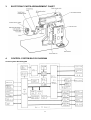
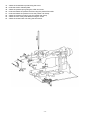
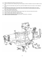
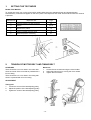
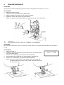
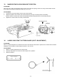
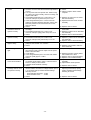
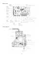
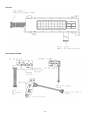
SERVICE MANUAL FOR
COMPUTERIZED SEWING MACHINE
ESp
9. 1997.
GENERAL INFORMATION
This service manual has been compiled for explaining repair procedures of ESp.
This was produced based on up-to-date product specifications at the time of issue, but there may have been changes
of specifications for the purpose of improvements.
Contact manufacturer or local sales company for information concerning such changes.
I .
II .
III.
IV .
PRINCIPAL MECHANISMS .........................................................................................1
DISASSEMBLING AND REASSEMBLING THE SEWING MACHINE .......................7
HOW TO ADJUST MECHANICAL ELEMENTS ........................................................17
HOW TO ADJUST ELECTRONIC ELEMENTS.........................................................29
CAUTION
1.
2.
3.
4.
Always use rubber gloves when handling printed circuit boards and never touch the metal portion of a printed
circuit board with bare hands.
Keep your body earthed in order to avoid generating static electricity.
Pack printed circuit boards in aluminum foil and avoid subjecting them to any form of impact during storage or
transportation.
Do not touch or damage the metal portion of a printed circuit board with a screwdriver or any other tool while
making repairs or the like.
PRINCIPAL MECHANISMS
I.
1.
2.
3.
4.
5.
6.
7.
8.
MECHANICAL CHART............................................................................................2
POWER TRANSMISSION CHART..........................................................................3
ELECTRONIC PARTS ARRANGEMENT CHART..................................................4
CONTROL SYSTEM BLOCK DIAGRAM................................................................4
MAIN MOTOR CONTROL .......................................................................................5
PATTERN GENERATOR.........................................................................................5
AUTOMATIC THREAD TENSION...........................................................................5
OTHER ELECTRONIC COMPONENT FUNCTIONS..............................................6
-1-
1.
MECHANICAL CHART
-2-
2.
POWER TRANSMISSION CHART
(A)
Generating mechanism of needle bar, thread take-up lever and zigzag movements
(B)
Mechanism of feed dog and rotary hook movement
-3-
3.
ELECTRONIC PARTS ARRANGEMENT CHART
4.
CONTROL SYSTEM BLOCK DIAGRAM
Control system block diagram
-4-
5.
MAIN MOTOR CONTROL
The main motor for the sewing machine is required to smoothly change from low speed to high speed without any
fluctuations due to load or temperature changes. To fully comply with this requirement, this model adopts PWM
control using FET.
6.
PATTERN GENERATOR
For conventional sewing machines, the pattern was generated by rocking the needle bar and the feed regulator by
means of a pattern cam onto which the pattern data had been mechanically engraved. In contrast to this, this model
stores the data electronically in memory and uses a feed pulse motor, side feed pulse motor and a zigzag pulse
motor to directly rock the needle bar and the feed regulator to generate the pattern. In addition, the pulse motors must
move the position of the needle while the needle is raised and stop it in the correct position (and similarly, they must
move the position of the feed regulator while the needle is lowered). Thus, highly-precise positioning and a fast
response speed are required. Because of this, the feed pulse motor, side feed pulse motor and a zigzag pulse motor
were adopted, and a simple open-loop structure circuit was employed.
Block diagram of pattern generator control
7.
AUTOMATIC THREAD TENSION
On former models, the operator adjusted the thread tension of the needle and bobbin threads by changing the
pressure between the tension disks.
On this model, however, the thread tension is calculated based on the feed, zigzag width, fabric thickness, and the
appropriate needle thread amount fed by the thread tension pulse motor.
This always gives you the correct thread tension regardless of thread, kinds of fabric or sewing speed.
Automatic thread tension block diagram
-5-
8.
OTHER ELECTRONIC COMPONENT FUNCTIONS
Start/stop switch
used to start and stop (SS) the machine. If you want to start sewing at low
speed, keep this switch depressed and start sewing.
Backstitch switch
used for backstitching and lockstitching. Backstitching is performed at low
speed in the reverse direction while the switch is pressed. For lockstitching,
three stitches are made at the current needle position and then sewing stops.
Needle position (UP/DOWN) switch ... used to change the needle position either up or down.
Automatic thread cutter switch
used to cut the thread automatically. When you press this switch, the machine
will automatically cut the thread, regardless of the needle position, and stop
with the needle at its upper position.
Touch panel
used to select pattern and input number required for sewing by simply touching
the display on the panel. This simplifies the operation for selecting the desired
pattern and number.
Buttonhole stitch switch
used to detect the edges of the buttonhole stitch by means of the buttonhole
stitch presser foot and lever.
Buttonhole stitch lever switch ............. used to detect whether the buttonhole stitch lever is raised or lowered.
Rotation sensor
detects the drive timing of zigzag, feed, side feed and thread feed pulse motor
and detects the vertical position of the needle. Also detects the turning angle of
the upper shaft by means of a photointerruptor and shutter installed on the
upper shaft.
Speed sensor
used to detect the rotation speed of the main motor.
detects the operating speed of the main motor by means of a photointerruptor
and shutter installed on the upper shaft.
Bobbin winder switch .......................... used to detect whether the bobbin winder has been set when winding the lower
thread.
Junction for foot controller .................. when using the foot controller, connect it to this terminal.
Transformer
used for driving the pulse motors, to illuminate the lamps and to supply power
to the electronic circuitry.
Lamp ................................................... is 12V 5W.
-6-
II.
DISASSEMBLING AND REASSEMBLING THE SEWING
MACHINE
1. DISASSEMBLING AND REASSEMBLING
THE OUTER PARTS AND MAIN PARTS ...............................................................8
2. LEAD WIRE ARRANGEMENT ..............................................................................16
-7-
1.
DISASSEMBLING AND REASSEMBLING THE OUTER PARTS AND MAIN
PARTS
1.
2.
3.
Remove the screw securing the face plate, and the face plate by sliding it to the left.
Remove the screw securing the free arm cover, and the free arm cover by sliding it to the left.
Remove the blind cap on the belt cover, the screw securing the belt cover, and the belt cover from below by
sliding it to the right.
Remove the two screws securing the base cover, slide the base cover to the left and then holding the front, slide
it to the left and out.
Remove the screw securing the front cover (near spool pin), and loosen the two screws (below jaw section on
face plate side, below free arm). Open the front cover toward the front, remove the four connectors and then the
front cover.
Remove the two screws securing the needle plate, and the needle plate.
Remove the three screws securing the rear cover, and the rear cover from the rear side.
4.
5.
6.
7.
-8-
8.
9.
10.
11.
12.
13.
14.
15.
16.
17.
18.
Remove the presser holder and needle.
Remove the 11 connectors, the two screws, and the main PC board.
Remove the two screws and handle holder assembly.
Remove the screw and thread winding assembly.
Remove the motor belt and pull out the motor connector. Remove the two screws and the main motor.
Remove the screw and the board set plate D.
Remove the side feed plate spring, the three screws and the SPM holder.
Remove the two screws, and pull out the thread guide cover from the tension link.
Remove the screw and the H block shaft holder assembly.
Remove the three springs and the needle bar block assembly.
Remove the two screws and the ZPM assembly.
-9-
19.
20.
21.
22.
23.
24.
25.
26.
Remove the two screws and the thread cutter unit.
Remove the screw and the inner rotary hook bracket.
Remove the presser bar clamp screw.
Remove the presser bar by lifting it from above, and the presser bar clamp.
Remove the presser spring screw and the presser bar spring.
Remove the presser lifter by pulling the presser lifting shaft straight out from the front.
Pull the tension releaser plate out forward.
Remove the screw and the thread take-up shaft.
-10-
27.
28.
29.
30.
31.
32.
33.
34.
35.
36.
Remove the two screws securing the upper shaft metal, and the upper shaft assembly.
Remove the screw and the N.P. board assembly.
Remove the screw and the tension pulley holder.
Remove the two feed rod tension springs.
Remove the metal presser screw and horizontal feed shaft bracket screw, and then remove the horizontal feed
assembly.
Remove the two screws and FPM holder assembly.
Remove the screw and the outer rotary hook assembly.
Remove the two metal presser screws, and remove the lower shaft assembly and timing belt.
Remove the connector, the two screws and the power supply unit assembly.
Remove the three screws and base plate assembly.
-11-
37.
38.
39.
40.
41.
42.
43.
44.
45.
46.
Attach the base plate using the three screws.
Attach the power supply unit assembly using the two screws, and insert the inlet connector.
While attaching the timing belt, assembly the lower shaft assembly using the metal presser and screw.
Position the outer rotary hook and three spacers with the lower shaft assembly (refer to following illustrations),
and attach using the screw.
Attach the FPM holder assembly using the two screws.
Attach the horizontal feed shaft bracket using the screw, and attach the horizontal feed assembly using the
metal presser and screw.
Insert the shaft of the feed rod into the feed block, and catch the two feed rod tension springs.
Attach the tension pulley holder using the screw.
Attach the N.P. board assembly using the screw.
Insert the timing belt over the upper shaft and attach using the metal presser and two screws.
-12-
47.
48.
49.
50.
51.
52.
53.
54.
Attach the thread take-up shaft using the screw.
Insert the tension releaser plate.
Attach the presser spring using the collar and screw.
Insert and attach the presser foot lifter using the presser lifter shaft.
Insert and attach the presser bar into the presser bar clamp.
Attach the presser bar spring onto the presser bar clamp.
Attach the inner rotary hook bracket using the screw.
Attach the thread cutter unit using the two screws.
-13-
55. Attach the ZPM holder assembly using the two screws.
56. Attach the needle bar block assembly using the three springs. (Insert the needle bar clamp into needle bar crank
rod)
57. Attach the H block shaft holder using the screw. (Insert the needle bar block arm into the pin on the needle bar
block.)
58. While inserting the thread guide cover assembly into the thread release link attach using the two screws.
59. Attach the SPM holder assembly using the three screws, and couple the horizontal feed shaft and side feed
plate using the side feed plate spring.
60. Attach the set plate D using the screws.
61. Connect the motor connector, attach the main motor using the two screws and catch the motor belt.
62. Attach the bobbin winder assembly using the screw.
63. Attach the handle holder assembly using the two screws.
64. Attach the main board assembly using the two screws. Connect the 11 connectors.
65. Attach the presser holder and needle.
-14-
66.
67.
68.
69.
70.
71.
72.
Attach the rear cover using the three screws.
Attach the needle plate assembly using the two screws.
Connect the four connectors, and attach the front cover using the three screws.
Insert the base cover into the base plate and attach using the two screws.
Attach the belt cover using the screw, and fit the blind cap on.
Attach the free arm cover using the screw.
Attach the face plate using the screw.
-15-
2.
LEAD WIRE ARRANGEMENT
-16-
III. HOW TO ADJUST MECHANICAL ELEMENTS
1.
2.
3.
4.
5.
6.
7.
8.
9.
10.
11.
12.
13.
14.
15.
16.
17.
18.
19.
20.
21.
SETTING THE TEST MODE..................................................................................18
TENSION OF MOTOR BELT AND TIMING BELT................................................18
NEEDLE DOWN POSITION ADJUSTMENT.........................................................19
TIMING OF NEEDLE AND ROTARY HOOK
(CLEARANCE BETWEEN THE NEEDLE AND THE ROTARY HOOK POINT) ..19
NEEDLE BAR HEIGHT..........................................................................................20
LOWER SHAFT .....................................................................................................20
FRONT/BACK, LEFT/RIGHT POSITION OF FEED DOG ....................................21
HEIGHT OF FEED DOG ........................................................................................21
PRESSER BAR HEIGHT .......................................................................................22
CHECKING DETECTION OF FABRIC THICKNESS ............................................22
POSITION OF BUTTONHOLE SWITCH LEVER ..................................................23
BOBBIN WINDER..................................................................................................23
INNER ROTARY HOOK BRACKET POSITION ...................................................24
LARGE ONE-POINT PATTERN SHAPE (SOFT ADJUSTMENT)........................24
FEED ADJUSTMENT (VERTICAL FEED) ............................................................25
INNER ROTARY HOOK TENSION .......................................................................25
NEEDLE THREADER ............................................................................................26
NEEDLE THREADER
(CHECKING THE HOOK POSITION IN HORIZONTAL DIRECTION) .................26
NEEDLE THREADER (EXCHANGE) ....................................................................27
NEEDLE THREADER (CHECKING THE HOOK IN STANDARD POSITION).....27
NEEDLE THREADER
(CHECKING THE HOOK POSITION IN VERTICAL DIRECTION) .......................28
-17-
1.
SETTING THE TEST MODE
BASIC TEST MODES
To set the test mode, turn on the power switch while holding down the start/stop button and backtack button
simultaneously. Numerals will appear on the touch panel. The respective test mode will be entered when the numeral
is pressed.
Test Mode No.
Adjustment Item
Page
2
Checking detection of fabric thickness
22
3
Pattern
4
Needle down position
19
5
Timing of needle and rotary hook
19
6
Horizontal position of feed dog
21
24, 25
The other test modes are used for factory adjustments.
2.
TENSION OF MOTOR BELT AND TIMING BELT
STANDARD
Motor belt
There should be a 4-6 mm slack in the motor belt
when the center of the motor belt is pressed with a
force of 200g.
There should be a 3-4 mm slack in the timing belt
when it is pressed with a force of 200g.
1.
2.
3.
ADJUSTMENT
Timing belt
1.
2.
3.
Loosen the screw of the belt adjusting pulley.
Adjust the position of the belt adjusting pulley.
Tighten the screw of the belt adjusting pulley.
-18-
Loosen the two screws securing the motor holder.
Adjust the belt tension by moving the motor holder.
Tighten the two screws.
3.
NEEDLE DOWN POSITION ADJUSTMENT
STANDARD
When test mode "4" is selected, the needle should be exactly at the middle of the needle plate hole in the needle
down position.
ADJUSTMENT
1.
2.
3.
4.
5.
6.
4.
Select test mode "4".
Turn the balance wheel to move the needle to the needle down position.
Loosen the screw securing the zigzag adjusting nut.
Turn the balance wheel to move the needle to the left and right, and then turn the zigzag adjusting nut by using
the box wrench to set the needle in the center of the needle hole.
Tighten the screw securing the zigzag adjusting nut.
Turn the balance wheel and check the needle down position.
TIMING OF NEEDLE AND ROTARY HOOK (CLEARANCE BETWEEN THE
NEEDLE AND THE ROTARY HOOK POINT)
STANDARD
When test mode "5" is selected and the needle is raised 2.9-3.3 mm from its lowest position, the rotary hook point
should be positioned at the right side of the needle.
The clearance between the needle and the rotary hook point should be 0.1 mm or less, and they should never touch
each other.
ADJUSTMENT
1.
2.
3.
4.
5.
Select test mode "5".
Loosen the three screws of the lower shaft gear.
Adjust the clearance between the needle and the rotary hook. (When the needle is
raised 2.9-3.3 mm from its lowest position, the rotary hook point should be
positioned at the right side of the needle.)
Tighten the three screws of the lower shaft gear.
Turn the adjusting screw, and set the clearance between the needle and the rotary
hook point to 0.1 mm or less. Make sure that the needle does not make contact with
the rotary hook point.
-19-
5.
NEEDLE BAR HEIGHT
STANDARD
When test mode "5" is selected, turn the balance wheel so that the needle meets the rotary hook point. At this time,
the clearance between the upper end of the needle eye and the bottom of the rotary hook point should be 1.0-1.4
mm.
ADJUSTMENT
1.
2.
3.
4.
5.
Select test mode "5".
Turn the balance wheel so that the needle meets the rotary hook point.
Loosen the screw of the needle bar block assembly.
Move the needle bar vertically to adjust the clearance to between 1.0-1.4 mm.
Tighten the screw of the needle bar block assembly.
NOTE: The needle clamp should be parallel to the side of the needle plate. If the needle bar is loose when you adjust the
needle bar height, it may result in sewing troubles.
6.
1.
2.
3.
LOWER SHAFT
Attach the bushing presser L temporarily so as the center of lower shaft is positioned higher by 1 mm against the
center of eccentric metal.
Install the outer rotary hook, then turn the eccentric metal and make sure that there is no backlash on the gears.
Tighten the screw on the bushing presser L.
-20-
7.
FRONT/BACK, LEFT/RIGHT POSITION OF FEED DOG
STANDARD
When test mode "6" is selected, move the feed dog front/back and left/right. At this time, the feed dog should not
contact the needle plate.
When the front/back position is the maximum feed amount, the clearance between the feed dog and needle plate at
the feed start position (when feed dog is at very front) should be 0.5 to 1.0. (Refer to illustration)
ADJUSTMENT
1.
2.
3.
4.
5.
6.
7.
8.
9.
8.
Select test mode "6".
Loosen the screw securing the horizontal feed plate.
In the test mode, align the feed dog's left/right position.
Tighten the screw securing the horizontal feed plate.
Move to the feed start position in the test mode.
Loosen the screw securing the horizontal feed arm.
Set the clearance between the feed dog and needle plate to 0.5 to 1.0.
Tighten the screw securing the horizontal feed arm.
After adjusting, press the thread cut button, and confirm that the thread
cutter operates correctly. If the thread cutter does not operate, readjust the
feed dog slightly to the back.
HEIGHT OF FEED DOG
STANDARD
When the balance wheel is turned to raise the feed dog to its highest position, the standard height of the feed dog
above the needle plate should be 0.9-1.1 mm.
ADJUSTMENT
1.
2.
3.
4.
Turn the balance wheel to raise the feed dog to its highest position.
Loosen the screw securing the vertical feed roller shaft.
Turn the vertical feed roller shaft to adjust the feed dog height to within 0.9-1.1 mm.
Tighten the screw securing the vertical feed roller shaft.
-21-
9.
PRESSER BAR HEIGHT
STANDARD
The clearance from the needle plate top to the bottom of the presser bar should be 7.0-7.5 mm.
ADJUSTMENT
1.
2.
3.
4.
10.
Raise the presser foot lifter.
Loosen the screw of the presser bar guide bracket.
Adjust the height of the presser bar by moving it vertically.
Tighten the screw of the presser bar guide bracket.
NOTE: The presser foot should be parallel to the feed dog hole of the needle plate.
CHECKING DETECTION OF FABRIC THICKNESS
STANDARD
When the fabric thickness is set to 0 mm and 3 mm in test mode "2", the buzzer should sound twice if operation is
normal.
ADJUSTMENT
1.
2.
3.
4.
5.
Select test mode "2".
Install the J presser foot and then lower the presser foot and set the needle
bar to the lowest position.
Press 0 mm on the display. (The buzzer should sound twice.)
Insert a spacer with a thickness of 3 mm beneath the J presser foot.
Press 3 mm on the display. (The buzzer should sound twice.)
NOTE: If the values read in steps (3) and (5) are normal, the buzzer will
sound twice each time. If they are not normal, the buzzer will sound
four times each time.
-22-
11.
POSITION OF BUTTONHOLE SWITCH LEVER
STANDARD
When the buttonhole lever is lowered, the clearance of front part of buttonhole foot is 1.5 mm and the presser foot
lever is lowered BH 0 should touch BH 1.
ADJUSTMENT
1.
2.
3.
12.
Turn on power switch and select pattern .
Fit the buttonhole foot (A). Adjust the clearance to 1.5 mm,
and lower the presser foot lever.
Adjust the position of buttonhole lever so that BH0 touches
BH1 when the buttonhole eccentric shaft is rotated.
NOTE: In case that the legs are shorter than the standard,
bend the BH 1 to be far from BH 0.
In case that the legs are longer than the standard,
bend the BH 2 to be close to BH 0.
BOBBIN WINDER
STANDARD
The thread should be wound parallel to the bobbin and around about 8590% of the bobbin at low speed.
The clearance between the bobbin winder switch and the bobbin winder
assembly should be 0.5-1.0 mm.
ADJUSTMENT
1. Loosen the bobbin winding guide screw.
2. Adjust the bobbin thread amount so that the thread is evenly wound
around the bobbin by moving the bobbin winding guide vertically.
3. Tighten the bobbin winding guide screw.
4. Loosen the screw securing the bobbin presser slightly.
5. Turn the bobbin presser to adjust the
bobbin thread amount.
6. Tighten the screw of the bobbin presser.
7. Set the bobbin winder assembly to the left.
8. Loosen the screw of the bobbin winder
switch.
9. Adjust the clearance between the bobbin
winder switch and the bobbin winder
assembly to 0.5-1.0 mm.
10. Tighten the screw of the bobbin winder switch.
13.
-23-
INNER
ROTARY
13.
INNER ROTARY HOOK BRACKET POSITION
STANDARD
When the inner rotary hook bracket and the rotary hook meet, the spring of the inner rotary hook bracket and the
inner rotary hook should overlap each other by 1.9-2.1 mm.
ADJUSTMENT
1.
2.
3.
14.
Loosen the screw securing the inner rotary hook bracket.
Adjust the position of the inner rotary hook bracket by moving it vertically and/or horizontally.
NOTE: Surface A of the inner rotary hook bracket should be perpendicular to the feeding direction.
Tighten the screw of the inner rotary hook bracket.
LARGE ONE-POINT PATTERN SHAPE (SOFT ADJUSTMENT)
STANDARD
When "3" pattern adjustment is selected in the test mode and the start button is pressed, the vertical and horizontal
separation of the "pattern" outline shape should be 1 mm or less.
ADJUSTMENT
1.
2.
3.
Select "3" pattern adjustment in the test mode.
Press the start button and sew the outline shape of the "pattern".
Adjust the pattern.
-24-
15.
FEED ADJUSTMENT (VERTICAL FEED)
STANDARD
Adjustment of the pattern should be possible in test mode "3".
ADJUSTMENT
1.
2.
3.
16.
Loosen the screw securing the pulse motor.
Rotate the pulse motor and adjust the pattern.
* Make sure not to contact the main PC board
during the adjustment.
Tighten the screw securing the pulse motor.
INNER ROTARY HOOK TENSION
STANDARD
While slowly pulling polyester thread #60 using a tension gauge, inner rotary hook tension should be 10-12g. The
difference between this and the tension for silk thread (#80) should be 2-3g.
ADJUSTMENT
1.
2.
Pass polyester thread #60 through the inner rotary hook correctly, and pull it using the tension gauge.
Adjust the tension by turning the screw to either the right or left using a screwdriver.
NOTE: After adjusting the tension, lock the screw with paint.
-25-
17.
NEEDLE THREADER
USING THE NEEDLE THREADER
There are a wide variety of different needles and
sewing machine threads available. The right ones
should be selected in accordance with the sewing
conditions. The accessory needle threader is designed
to make threading of needles easier, but it cannot
handle every single circumstance of use
(combinations of needle and thread) that may occur. It
can be used with some combinations but not with
others, and if it can be used, the pattern may not be
sewn correctly due to the particular sewing conditions.
Do not use the needle threader without gaining a
thorough understanding of how to use it, otherwise the
needle threader may be damaged or needle threading
may not be possible. Be sure to read and understand
the following so that you can handle customer
complaints.
NOTE:
1. Needle threader accepts only circled needle and
thread combinations.
2. Combinations marked with a * are not
recommended since they might lead to the
breakage of needle threader imperfect
performance.
3. Lower the presser foot when you use needle
threader.
4. Nylon transparent thread is applicable in needle
18.
#14-16.
5. Do not turn the balance wheel when using needle
threader.
6. Do not lower the needle threader lever while the
machine is running. If it is lowered, the needle
threader may be broken, rendering it unusable.
Besides this, it may cause the needle to break, which
could result in injury.
7. If a #9 needle is used, the variation in needle precision
may result in the needle being slightly difficult to
thread.
8. Needle should be located above needle plate by more
than 8 mm for threading.
9. Needle threader does not work when you use the
side-cutter.
Thread the needle before attaching the side cutter.
Thread
#30
#50
#60
#80
#100
#120
#9
´
´
´
O
O
O
#11
´
´
O
O
O
*
#14
´
O
O
O
*
*
#16
*
O
O
*
*
*
#18
*
*
*
*
*
*
Needle
NEEDLE THREADER
(CHECKING THE HOOK POSITION IN HORIZONTAL DIRECTION)
STANDARD
The measure from inside of the hook guard to the center point of hook is 0.42 mm.
CHECK
As sewing needle HA X1 (#14) is standard, so prepare five brand-new sewing needles HA X1 (#14) and check by
changing all of these.
After Checking,
1. In case that, hook goes through eyelet of all needles ....................There is no problem.
2. In case that, hook does not go through eyelet of all needles .........Adjust by bending hook.
3. In case that, hook does not go through eyelet of some needles....Needles through which the hook does not go
through are defective.
(Example for checking)
When you check five brand-new sewing needles HA X1 (#9) on condition that it achieves above first case, if the hook
does not go through eyelet of all of these needle, all five needles are defective and you judge the hook position is not
defective.
ADJUSTMENT
In case the hook is defective after above checking, adjust the hook by bending with pliers. Do not bend the hook
guard at this time.
-26-
19.
NEEDLE THREADER (EXCHANGE)
HOW TO EXCHANGE NEEDLE THREADER
1.
2.
3.
4.
20.
Remove the needle and lower the presser foot.
Push down the needle threader and take it out.
Place a new one so that the guide is immediately under the groove as shown in figure A .
Push the needle threader all the way up so that the guide is fits into the groove.
NEEDLE THREADER
(CHECKING THE HOOK IN STANDARD POSITION)
STANDARD
1.
2.
The clearance between the top of hook and the top of needle eye is 0 mm.
Threading is possible when needle is located higher than 8 mm from the needle plate.
CHECK (refer to illustration)
Case A
Hook position is too high. (Hook hits needle and cannot go through needle eye.)
Case B
Hook position is too low. (Hook goes through needle eye but it catches bottom part of needle eye.)
-27-
21.
NEEDLE THREADER
(CHECKING THE HOOK POSITION IN VERTICAL DIRECTION)
Case A
Adjust needle threader position setter slightly down and
check that the clearance between the top of hook and
top of needle eye is 0 mm.
Case B (Hook point is too low)
Adjust needle threader position setter slightly up and
check the clearance between the top of hook and top of
needle eye is 0 mm.
Check that the needle threader position setter a and
the needle bar crank rod assembly b is parallel.
In case part a and part b is not parallel or the hook
does not work, readjust needle threader by loosening
the screw.
If a and b are not parallel, the needle threader will
not be held by the needle threader position setter (refer
to Fig. 1), the hook will not enter the eyelet of the
needle (hook will not move) and the needle will not be
threaded when the needle threader lever is lowered. In
this case, loosen the screw securing the needle
threader position setter and turn the needle threader
position setter slightly to the left to make it parallel.
In addition, if the needle threader position setter is
turned too far so that it is still not parallel too left, it may
hit other parts, causing damage (refer to Fig. 2). If a
part is damaged, it must be replaced. If no part is
damaged, loosen the screw securing the needle
threader position setter and turn the needle threader
position setter slightly to the right to make it parallel.
-28-
IV. HOW TO ADJUST ELECTRONIC ELEMENTS
1. When power is turned on, buzzer does not sound and nothing
appears on display ...............................................................................................30
2. After the power is turned on, pulse motors do not return to
their home positions with respect to the needle position................................30
3. Pattern cannot be selected..................................................................................30
4. Main motor does not run .....................................................................................30
5. Operation of main motor is not stable, maximum speed operation
is not possible, or speed cannot be adjusted ...................................................31
6. Correct patterns are not created.........................................................................31
7. Buttonholes are not stitched correctly ..............................................................31
8. Manual operation of feed and zigzag pulse motors is not possible ...............31
9. Vertical movement of needle bar and backstitch operation are abnormal ....31
10. Foot controller does not operate normally when depressed...........................31
11. Thread tension is not correct ..............................................................................32
12. Needle bar release mechanism does not operate correctly ............................32
13. Thread cutter does not operate correctly ..........................................................32
14. Display does not appear clearly .........................................................................32
15. The LCD light does not light................................................................................32
16. Thread cannot be wound around bobbin...........................................................32
17. Needle thread breakage detector does not operate correctly .........................32
-29-
HOW TO ADJUST ELECTRONIC ELEMENT
* You must turn off the power and remove connectors from printed circuit boards before measuring resistance.
PROBLEM
1. When power is turned
on, buzzer does not
sound and nothing
appears on display.
2. After the power is
turned on, pulse
motors do not return to
their home positions
with respect to the
needle position.
(Zigzag pulse motor
when needle bar is
raised and feed and
side feed pulse motors
when needle bar is
lowered.)
3. Pattern cannot be
selected.
CHECK
1) Has the display contrast been adjusted?
2) If the voltage between both inlet terminals is
measured when the power cord is plugged in, is the
standard voltage (120 VAC, 220V, 230V, 240V)
displayed?
3) When power switch is set to on, is resistance between
both ends less than 1 W?
4) Remove connector CN13 from the power supply
board, and check following voltages using a tester:
Voltage between pins 2 and 3 should be 5 VDC.
Voltage between pins 4 and 5 should be 20 to 30 VDC.
5) Is fuse blown?
6) Others
1) Are the resistances between the connector pins given
below normal for the pulse motors which do not return
to the home position?
Zigzag
(CN2)........ 1-3, 2-4 ® 8-10 W
Feed
(CN4)........ 1-3, 2-4 ® 8-10 W
Horizontal (CN1)........ 1-3, 2-4 ® 8-10 W
2) Set the home position for the same pulse motors
irrespective of needle position.
3) Is a fuse blown?
4) Is the voltage between pins 4-5 normal when the
connector (CN13) which is output from the power
supply board is disconnected?
Between 4-5
20-30 VDC
5) Others
1) Does switch on SS PC board remain pressed?
2) When the foot controller is connected, does it remain
depressed?
3) Others
4. Main motor does not
run.
1) Does balance wheel rotate easily?
2) Is main motor connector (CN2 on power supply unit)
attached properly?
3) Is resistance of both ends on main motor connector
(CN2 on power supply unit)
120V spec 30-50W or
220-240V spec 110-150W?
4) Do start/stop switch, backstitch switch, needle
position switch, and thread cutter switch operate
correctly?
Resistances between ends of each switch should be;
under 1W when switch is pressed.
infinite when switch is released.
5) Is presser foot lifter lowered? Does presser foot
switch operate correctly?
When presser foot lifter is lowered, voltage between
pins 2-1 of fabric thickness detector (CN6) is under
2VDC.
When presser foot lifter is raised, it is over 3VDC.
6) Others
-30-
REMEDY
1) Adjust the contrast.
2) Replace the power cord.
3) Replace power supply unit
assembly.
4) Replace power supply unit
assembly.
5) Replace fuse after correcting defect
that caused fuse to blow.
6) Replace main PC board assembly.
1) Replace the pulse motor which
shows an abnormality.
2) Replace NP board assembly.
3) Replace fuse after correcting defect
that caused fuse to blow.
4) Replace power supply unit
assembly.
5) Replace main PC board assembly.
1) Adjust or exchange SS PC board
assembly.
2) Check foot control unit operation.
3) Replace LCD module, or main PC
board.
1) Adjust mechanical positions to
reduce the heavy torque.
2) Check connector connection.
3) Replace main motor.
4) Replace SS PC board assembly.
5) Check fabric thickness detection or
replace fabric thickness sensor
assembly.
6) Replace main PC board or power
supply unit assembly.
5. Operation of main
motor is not stable,
maximum speed
operation is not
possible, or speed
cannot be adjusted.
6. Correct patterns are
not created.
7. Buttonholes are not
stitched correctly.
8. Manual operation of
feed and zigzag pulse
motors is not possible.
9. Vertical movement of
needle bar and
backstitch operation
are abnormal.
10. Foot controller does
not operate normally
when depressed.
1) When turning on power and moving speed slide, does
voltage between pins 3 and 2 of connector CN10 (for
speed slide) change from 0 to 5 VDC?
2) When turning balance wheel, do voltages between
pins 2-1, pins 4-1, pins 5-1, and 6-1 of connector CN5
(for NP board) change to either 0 or 5 VDC?
3) Others
1) If the power is turned off and the needle bar is moved
horizontally by hand, does it move easily?
2) Are the resistances between the connector pins for
the zigzag, feed and side feed pulse motors normal?
Zigzag
(CN2).................. 1-3, 2-4 ® 8-10 W
Feed
(CN4).................. 1-3, 2-4 ® 8-10 W
Side feed (CN1).................. 1-3, 2-4 ® 8-10 W
3) Do the voltages between pins 2-1, 5-1 and 6-1 of the
N.P. board assembly connector (CN5) alternate
between 0-5 VDC when the sewing machine is turned
slowly?
4) Others
1) Is the stitch foot set correctly?
2) Is the resistance between pins 4-5 of the BH switch
connector (CN7) normal?
When buttonhole lever is lowered .... 1 W or less
When buttonhole lever is raised ........................ ¥
3) When the buttonhole lever is lowered and in the
conditions below, is the resistance between pins 1-2
and 2-3 of the BH switch connector (CN7) normal?
Between 1-2 Between 2-3
Buttonhole lever is
pulled forward...................1 W or less
¥
Buttonhole lever is
pushed back.....................
¥
1 W or less
4) Others
1) Do manual keys of feed and zigzag pulse motors turn
off and on normally, and do the LCDs change?
2) Are the resistances between the pins below of the
feed and zigzag pulse motors normal?
Feed
(CN4).................. 1-3, 2-4 ® 8-10 W
Zigzag
(CN2).................. 1-3, 2-4 ® 8-10 W
3) Others
1) Are the resistances between both sides of the SS PC
board assembly switches 1 W or less and in the k W
range respectively when the switches are turned on
and off?
2) Do the voltages between pins 2-1, 4-1, 5-1 and 6-1 of
the NP board assembly connector (CN5) alternate
between 0-5V when the sewing machine is turned
slowly?
3) Is the bobbin winder switch turned off?
4) Others
1) Is the resistance between pins 2-3 of the pin jack
connector (CN14) 1 W or less when there is no pin
jack and ¥ when there is a pin jack?
2) Does the resistance between pins 1-3 of the pin jack
connector (CN14) change from the low W range to 10
k W when there is a pin jack and the foot controller is
depressed?
3) Others
-31-
1) Replace VR board assembly.
2) Replace NP board assembly.
3) Replace main PC board.
1) Adjust the installation position so
that it moves easily.
2) Replace pulse motor or lead wire
assembly.
3) Replace NP board assembly.
4) Replace main PC board assembly.
1) Check stitch foot.
2) Adjust button hole lever or replace
BH switch assembly.
3) Adjust button hole lever or replace
BH switch assembly.
4) Replace main PC board assembly.
1) Replace LCD module.
2) Replace feed stepping motor,
zigzag stepping motor or lead wire
assembly.
3) Replace main PC board assembly.
1) Replace SS PC board assembly.
2) Replace NP board assembly.
3) Adjust the bobbin winder
mechanism.
4) Replace main PC board assembly.
1) Replace pin jack assembly.
2) Replace foot controller or jack
assembly.
3) Replace main PC board assembly.
11. Thread tension is not
correct.
12. Needle bar release
mechanism does not
operate correctly.
13. Thread cutter does not
operate correctly.
14. Display does not
appear clearly.
15. The LCD light does not
light.
16. Thread cannot be
wound around bobbin.
17. Needle thread
breakage detector does
not operate correctly.
1) Is thread route correct?
2) Are the 0 mm and 3 mm fabric thickness adjustments
correct?
3) Turn off power and lower presser foot. When turning
AT pulse motor gear manually, does it turn easily, and
together with roller?
4) Are resistances between pins 1-3 and pins 2-4 of
connector CN3 (for AT pulse motor) 8 to 10 W?
5) Is the voltage between pins 2-1 of the connector
(CN6) for the fabric thickness detection under 2 VDC
when the presser foot is lowered and over 3 VDC
when it is raised?
6) Others
1) Does needle bar release mechanism operate
smoothly?
2) Are resistances between pins 1-3 and 2-4 of
connector CN2 (for zigzag pulse motor) 8 to 10 W?
3) Others
1) Does the thread cutter move lightly?
2) Are resistances between pins 1-3 and 2-4 of
connector CN4 (for feed pulse motor) 8 to 10 W?
3) Others
1) Is the voltage between pins 8-7 of the connector
(CN9) for LCD module -5 to -10VDC?
2) Others
1) Is the voltage between pins 4-5 20 to 30 VDC when
the connector (CN7) which is output from the power
board is disconnected?
2) Is fuse blown?
3) Is the voltage between pins 9-10 of the LCD module
connector (CN9) approx. 9 VDC?
4) Others
1) Is resistance between both ends of connector CN15
(for bobbin winder switch) under 1 W when thread is
wound, or infinity in other cases?
2) Is bobbin winder attached correctly?
3) Others
1) When passing thread through thread route and setting
thread condition as follows, is voltage between pins 21 of connector CN8 (for needle thread breakage
detector) correct?
When thread is tensioned... 0 VDC
When thread is loose.......... 5 VDC
2) Others
-32-
1) Check thread route.
2) Check.
3) Adjust or replace ATPM holder
complete.
4) Replace AT pulse motor or ATPM
lead wire assembly.
5) Replace thickness sensor of fabric
assembly.
6) Replace main PC board.
1) Adjust needle bar release
mechanism.
2) Replace Z pulse motor or ZPM lead
wire assembly.
3) Replace main PC board assembly.
1) Adjust the thread cutter mechanism.
2) Replace F pulse motor or FPM lead
wire assembly.
3) Replace main PC board assembly.
1) Replace main PC board assembly.
2) Replace LCD module or main PC
board assembly.
1) Replace the power board assembly.
2) Replace fuse after correctly defect
that caused fuse to blow.
3) Replace main PC board assembly.
4) Replace LCD module assembly.
1) Replace bobbin winder switch
assembly.
2) Adjust bobbin winder position.
3) Replace main PC board.
1) If condition does not change after
adjusting thread take-up spring,
replace needle thread breakage
detecting PC board.
2) Replace main PC board.
Main PC board
Power supply unit
-33-
LCD unit
Other PC boards (985)
-34-
ESp
H7060088
-35-