1
Design,Installation&Maintenance instruction
R410A HEAT PUMP 50/60Hz
AV08NMSETA
AV10NMSETA
AV12NMSETA
SYJS-08-2013REV.B
Edition:2013-08
1
CONTENTS
1. General information------------------------------------------------------------3
2. Specification----------------------------------------------------------------------4
3. Indoor model list----------------------------------------------------------------5
4. Refrigerant circuit-------------------------------------------------------------- 6
5. Dimension-------------------------------------------------------------------------7
6. Wiring diagram------------------------------------------------------------------ 8
7. Capacity table---------------------------------------------------------------------9
8. Performance curves-----------------------------------------------------------33
9. Outdoor installation-----------------------------------------------------------37
10.
Electric installation--------------------------------------------------------57
11.
Trial operation --------------------------------------------------------------60
12.
Dip switch setting------------------------------------------------------- 70
13.
Digital tube display------------------------------------------------------ 72
14.
Failure code------------------------------------------------------------------73
15.
Trouble shooting------------------------------------------------------------78
97
APPENDIX-----------------------------------------------------------------------------
2
1. General information
MRVIII-S adopts refrigerant R410A. It is with DC inverter technology, high efficiency
and energy saving, intelligent control, etc. The system can realize max 1-19 .
Features:
1. High efficiency and energy saving
1.1 Adopt High efficient rotary compressor, compact design, compared to the scroll
compressor smaller, more efficient in part load operation!
1.2 The compressor bottom design oil temperature sensor, it can control heater on/off
station, reduced the compressor standby ratio, saving energy.
1.3 Adopt high frequency DC motor, improve efficiency
1.4 Stepless converter technique, compressor adopt 180° vector
control technology, improve the running ratio 17%.
1.5 High efficiency heat exchanger
1.6 Adopt refrigerant control technology, remove high-pressure accumulator, reduce the
amount of refrigerant.
1.7 Outdoor unit can automatic recover refrigerant.
2. Comfortable and quieter
2.1 Large diameter streamlined double axial fan design, reduces vibration and reduce
pressure loss
2.2 Units with silent operation function, Outdoor Noise is 45 dB(A)
3. Beautiful and more convenient
3.1 Miniaturization side wind design, small footprint, can be easily placed。
3.2 Long pipe, according to the actual needs ,choosing the right outdoor unit installation
location
3.3 4 way piping is possible ( front, rear, right, down), More flexible installation
3.4 Reserve space above the unit, removable roof for repairing, maintenance more
convenient
3
2. Specification
cooling heating
Electrical characteristics
Equivalent HP
Model
Nominal cooling capacity(kW)
Nominal heating capacity(kW)
Heating capacity at low temp.(kW)
Power source
IP level
Operating/Max.current(A)
8
10
12
AV08NMSETA AV10NMSETA AV12NMSETA
33.50
22.6
28
37.50
25
31.5
29.00
21.2
25.6
3N ~ .380-400V.50/60Hz
IP24
IP24
IP24
16.4/26
9.6 / 17.2
13.2 / 23.8
Operating/Max.consumption(kW)
5.79 / 10.42
8.0 / 14.4
9.82/15.4
Operating/Max.current(A)
9.0 / 16.2
12.4 / 22.3
16.2/25.3
Operating/Max.consumption(kW)
5.43 / 9.78
7.5 / 12.4
9.62/15.0
6.5
9
11.5
Power consumption when heating at low temp.(kW)
Output power of outdoor motor(kW)
Exterior dimensions(mm)
Weight(Kg)
Exterior colour
Compressor type
Compressor model
Oil charge(ml)
Oil model
Outdoor motor rate(rpm)
Outdoor airflow(m )
Refrigerant (R410A) charge(Kg)
Gas piping(mm)
Liquid piping(mm)
Noise level(dB(A)
Max. indoor units
0.145+0.18
0.145+0.18
0.145+0.18
1636×1050×400 1636×1050×400 1636×1050×400
168
168
168
ivory white
ivory white
ivory white
Twin rotary
LNB53F
LNB53F
LNB53F
2000
2000
2000
FV50S
FV50S
FV50S
770+850
770+850
770+850
10000
10000
10000
7.4
7.4
7.4
φ19.05
φ22.22
φ25.4
φ9.52
φ12.7
φ12.7
55
58
60
13
16
19
Norminal condition: indoor temperature (cooling): 27℃DB/19℃WB, indoor temperature (heating):
20℃DB/14.5℃WB Outdoor temperature(cooling): 35℃DB/24℃WB, outdoor temperature(heating):
7℃DB/6℃WB
The noise level will be measured in the third octave band limited values in the semi-anechoic chamber,
using a Real Time Analyser calibrated sound intensity meter. It is a sound pressure noise level.
4
3. Indoor model list
4-WAY CASSETTE TYPE / PB-700lB
AB092MCERA
AB122MCERA
AB162MCERA
HIGH WALL EEV INSIDE
AS072MGERA
AS092MGERA
AS122MGERA
AS162MGERA
AS182MGERA
AS242MGERA
4-WAY CASSETTE TYPE /PB-950JB
AB182MCERA
AB242MCERA
AB282MCERA
MED ESP DUCT TYPE(80/120Pa))
AD182MZERA
AD242MZERA
AD282MZERA
AB302MCERA
AB382MCERA
AB482MCERA
AD302MNERA
AD382MNERA
AD482MNERA
LOW ESP DUCT TYPE
AD072MLERA
AD092MLERA
AD122MLERA
MED ESP DUCT TYPE(50/96Pa)
AD182MMERA
AD242MMERA
AD282MMERA
AD162MLERA
AD182MLERA
AD242MLERA
AD302MMERA
AD382MMERA
AD482MMERA
HlGH ESP DUCT TYPE
AD182MHERA
AD242MHERA
AD282MHERA
CONVERTlBLE TYPE
AC092MCERA
AC122MCERA
AC162MCERA
AC182MCERA
AC242MCERA
AD302MHERA
AD382MHERA
AD482MHERA
AD722MHERA
AD962MHERA
SLIM LOW ESP DUCT
AD072MSERA
AD092MSERA
AD122MSERA
AD162MSERA
AD182MSERA
AD242MSERA
2 WAY CASSETTE/1055IB
AB072MBERA
AB092MBERA
AB122MBERA
AB162MBERA
AB182MBERA
AC282MEERA
AC302MEERA
AC382MFERA
AC482MFERA
BUILIT-IN FLOOR STANDING
AE072MLERA
AE092MLERA
AE122MLERA
AE162MLERA
AE182MLERA
AE242MLERA
CONSOLE TYPE
AF072MAERA
AF092MAERA
AF122MAERA
AF182MAERA
The information for indoor units refer to the manual of MRVIII-C
5
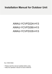
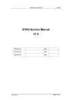
high pressure sensor
6
charge valve
liquid pipe valve
Td
high pressure switch
gas pipe valve
inverter
compressor
SV1
Ts
low pressure sensor
SV2
defrost sensor
defrost
sensor
PMV
condensor
condensor
4. Refrigerant circuit
ambient temp. sensor
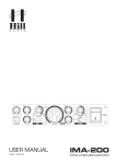
5. Dimension
:LULQJKROHV˓
5HIULJHUDQW SLSH RXWOHW
˓GUDLQKROH
Mounting hole
7
;
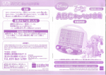
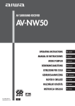
6. Wiring diagram
HPS Td Te1 Te2 Ts
Ta
Ps
0150513195
Pd Toil
P
ACL
6.3A 250VAC
HEATER2
ACN
FUSE1
LD1
BM2
12345678
LED4 LED2
ON
12345678
SV1
CN32
BM1
ON
CN18
CN9
CN31
CN30
CN20
M
CN8
SW01
CONTROL BOARD
CN2
CN24
CN25
SW3
SW1
ACFAN2 SW4
M
~
INV Board
SW2
M
CA
LED3
CN1
CN11
LED1
R
+
W
+
4
+ ~
~
~
-
1
B
L1 L2 L3 N E
PTC CB1
Y
-
5
2
B
3
W
W
R1 R2
-
rectifier
R
CN8
U V W
N
W
B
CN7
B
P
REACTOR
W
CN3
CN10
DCFAN1
Earth Wire
SW02
Tfin
CN16
HEATER
LED
DISPLAY
EEV
CN17
4WV
LD3
CN21
CN26
SV2
LD2
CN1 CN2 CN3 CN4 CN5 CN6 CN7 CN29 CN28 CN30
W
B
COMP
CB2
Y
T3
T2
L3
L2
T1
L1
B
AC Contactor
Noise Filter
L1 L2 L3 N E
symbol
<WARNING>
L1L2 L3 N
R W BL B
PQ
Ta
<SYMBOL>
Please power off firstly for about 10
minutes before checking control box,
and make sure the voltage between
P and N below 20V.
<NOTES>
Ts
·Please check the power firstly before test , and make
sure the crankcase heater powering on for 12 hours
at least to protecting compressor.
·The switch BM1-1 is used for locking the indoor units
number, the initial situation is “ OFF”. After power on,
the display board will display 【U**】, “**” indicates
the number of Indoor units that the outdoor unit can
communicate with. If it can match the actual number
of indoor units, please change “OFF” to “ON”, or else
fix the communication problem firstly.
·Forbid connecting the power wire to the “P” and “Q”,
otherwise the control board will be damaged.
·Please make sure the earth wire connecting the grounding hole on the electric box firmly.
symbol
HEATER,2
SV1
SV2
4WV
CA
ACFAN2
DCFAN1
HPS
Td
Te1,2
8
signification
Crankcase
heater
Unloading valve
Spay valve
4-way valve
Capacitor
AC fan motor
DC fan motor
High pressure
switch
Discharging
temp. sensor
Defrost
temperature
sensor
signification
Suction temperature
sensor
Ambient
temperature
sensor
Pd
High pressure sensor
Ps
Low pressure sensor
Toil
Oil temperature sensor
EEV Electronic expansion
valve
Tfin
IPM temperature
sensor
CB1,2 Electrolytic capacitor
R
W
BL
B
Y
Red
White
Blue
Black
Yellow
7. Capacity table
Capacity Outdoor
factor
temp.
(℃ DB)
130%
120%
110%
-5
0
5
10
15
20
25
30
35
41
43
-5
0
5
10
15
20
25
30
35
41
43
-5
0
5
10
15
20
25
30
35
41
43
14(℃ )
TC
PI
KW KW
20.40 2.57
20.40 2.58
20.4 2.60
20.4 2.74
20.4 2.87
20.4 3.01
20.4 3.61
20.4 4.25
20.4 5.04
20.4 5.75
20.4 6.23
18.90 2.41
18.90 2.42
18.9 2.44
18.9 2.49
18.9 2.61
18.9 2.74
18.9 3.23
18.9 3.76
18.9 4.52
18.9 5.20
18.9 5.57
17.30 2.13
17.30 2.14
17.3 2.16
17.3 2.26
17.3 2.36
17.3 2.48
17.3 2.87
17.3 3.41
17.3 4.00
17.3 4.68
17.3 5.04
16(℃ )
TC
PI
KW KW
24.10 3.11
24.10 3.12
24.1 3.14
24.1 3.30
24.1 3.44
24.1 3.81
24.1 4.57
24.1 5.45
24 6.35
23.1 6.84
22.6 7.22
22.20 2.84
22.20 2.85
22.2 2.87
22.2 3.01
22.2 3.14
22.2 3.39
22.2 4.08
22.2 4.83
22.2 5.70
22.2 6.69
22.2 6.94
20.40 2.57
20.40 2.58
20.4 2.60
20.4 2.72
20.4 2.85
20.4 3.00
20.4 3.59
20.4 4.27
20.4 5.03
20.4 5.90
20.4 6.27
AV08NMSETA
Indoor temp.(℃ WB)
18(℃ )
19(℃ )
20(℃ )
TC
PI
TC
PI
TC
PI
KW KW KW KW KW KW
27.80 3.60 29.70 4.07 30.90 4.52
27.80 3.63 29.70 4.10 30.90 4.56
27.8 3.68 29.7 4.15 30.9 4.62
27.8 3.86 29.7 4.17 30 4.65
27.8 4.03 28.7 4.34 29.1 5.03
27.5 4.61 27.8 4.64 28.1 5.12
26.5 5.21 26.8 5.23 27.2 5.79
25.6 5.83 25.9 5.83 26.3 6.43
24.7 6.42 25 6.45 25.3 7.13
23.8 6.91 24.1 6.95 24.5 7.69
23.2 7.87 23.6 8.01 24 8.89
25.70 3.13 27.30 3.53 29.40 4.20
25.70 3.16 27.30 3.56 29.40 4.24
25.7 3.21 27.3 3.61 29.4 4.30
25.7 3.53 27.3 3.79 29 4.45
25.7 3.70 27.3 3.96 28.7 4.57
25.7 4.17 27.3 4.59 27.7 5.09
25.7 5.01 26.4 5.20 26.8 5.74
25.1 5.77 25.5 5.80 25.9 6.42
24.2 6.37 24.6 6.41 24.9 7.08
23.3 6.84 23.6 6.86 24 7.54
22.8 7.69 23.1 7.87 23.4 8.70
23.50 2.97 25.00 3.22 26.60 3.76
23.50 3.00 25.00 3.25 26.60 3.80
23.5 3.05 25 3.30 26.6 3.86
23.5 3.20 25 3.44 26.6 4.05
23.5 3.34 25 3.57 26.6 4.23
23.5 3.68 25 4.03 26.6 4.85
23.5 4.41 25 4.68 25.9 5.29
23.5 5.24 25 5.69 25.2 6.37
23.5 6.19 24.1 6.36 24.4 7.03
22.8 6.79 23.2 6.80 23.5 7.40
22.2 7.21 22.7 7.58 23 8.65
9
Cooling mode
22(℃ )
TC
PI
KW KW
31.80 5.08
31.80 5.12
31.8 5.18
30.7 5.43
29.7 5.60
28.8 6.01
27.9 6.37
26.9 7.07
26 7.86
25.1 8.57
24.6 9.87
31.10 4.95
31.10 4.99
31.1 5.05
30.2 5.26
29.3 5.51
28.3 5.59
27.4 6.33
26.4 7.05
25.5 7.79
24.6 8.50
24 9.80
30.60 4.62
30.60 4.66
30.6 4.72
29.7 4.80
28.7 4.88
27.8 5.56
26.5 6.05
25.9 7.00
25 7.74
24 8.46
23.5 9.56
24(℃ )
TC
PI
KW KW
32.30 5.70
32.30 5.75
32.3 5.82
31.4 5.83
30.5 6.50
29.5 6.71
28.6 7.20
27.7 7.62
26.7 8.26
25.9 9.02
25.3 10.42
31.70 5.53
31.70 5.58
31.7 5.65
30.8 5.57
29.9 5.96
28.9 6.39
28 6.64
27 7.42
26.1 8.19
25.2 9.00
24.7 10.37
31.30 5.09
31.30 5.14
31.3 5.21
30.3 5.19
29.3 5.30
28.4 5.83
27.1 6.89
26.5 7.36
25.6 8.12
24.7 8.88
24.1 10.06
Capacity Outdoor
factor
temp.
(℃ DB)
100%
90%
80%
-5
0
5
10
15
20
25
30
35
41
43
-5
0
5
10
15
20
25
30
35
41
43
-5
0
5
10
15
20
25
30
35
41
43
14(℃ )
TC
PI
KW KW
15.70 1.99
15.70 2.00
15.7 2.02
15.7 2.03
15.7 2.12
15.7 2.23
15.7 2.52
15.7 2.98
15.7 3.50
15.7 4.11
15.7 4.47
14.20 1.69
14.20 1.70
14.2 1.72
14.2 1.81
14.2 1.90
14.2 1.99
14.2 2.19
14.2 2.59
14.2 3.05
14.2 3.56
14.2 3.93
12.60 1.51
12.60 1.52
12.6 1.54
12.6 1.60
12.6 1.67
12.6 1.75
12.6 1.89
12.6 2.23
12.6 2.63
12.6 3.13
12.6 3.61
16(℃ )
TC
PI
KW KW
18.50 2.31
18.50 2.32
18.5 2.34
18.5 2.45
18.5 2.56
18.5 2.68
18.5 3.14
18.5 3.74
18.5 4.41
18.5 5.11
18.5 5.48
16.70 2.05
16.70 2.06
16.7 2.08
16.7 2.18
16.7 2.27
16.7 2.37
16.7 2.72
16.7 3.23
16.7 3.80
16.7 4.45
16.7 4.70
14.80 1.80
14.80 1.81
14.8 1.83
14.8 1.91
14.8 2.00
14.8 2.09
14.8 2.33
14.8 2.76
14.8 3.25
14.8 3.79
14.8 4.11
AV08NMSETA
Indoor temp.(℃ WB)
18(℃ )
19(℃ )
20(℃ )
TC
PI
TC
PI
TC
PI
KW KW KW KW KW KW
21.30 2.70 22.60 2.88 24.20 3.36
21.30 2.73 22.60 2.91 24.20 3.40
21.3 2.78 22.6 2.96 24.2 3.46
21.3 2.87 22.6 3.09 24.2 3.63
21.3 3.00 22.6 3.23 24.2 3.79
21.3 3.20 22.6 3.50 24.2 4.21
21.3 3.85 22.6 4.21 24.2 5.05
21.3 4.56 22.6 5.00 24.2 5.97
21.3 5.38 22.6 5.79 24 6.99
21.3 6.30 22.6 6.64 23.1 7.65
21.3 6.67 22.6 7.28 22.5 8.07
19.30 2.36 20.50 2.53 21.80 2.97
19.30 2.39 20.50 2.56 21.80 3.01
19.3 2.44 20.5 2.61 21.8 3.07
19.3 2.55 20.5 2.74 21.8 3.23
19.3 2.66 20.5 2.87 21.8 3.37
19.3 2.79 20.5 3.02 21.8 3.61
19.3 3.31 20.5 3.61 21.8 4.34
19.3 3.93 20.5 4.30 21.8 5.15
19.3 4.63 20.5 5.06 21.8 6.08
19.3 5.43 20.5 5.58 21.8 7.12
19.3 5.78 20.5 6.20 21.8 7.69
17.10 2.05 18.30 2.22 19.30 2.60
17.10 2.08 18.30 2.25 19.30 2.64
17.1 2.13 18.3 2.30 19.3 2.70
17.1 2.23 18.3 2.40 19.3 2.83
17.1 2.34 18.3 2.50 19.3 2.95
17.1 2.44 18.3 2.63 19.3 3.09
17.1 2.81 18.3 3.07 19.3 3.67
17.1 3.34 18.3 3.65 19.3 4.35
17.1 3.93 18.3 4.30 19.3 5.14
17.1 4.58 18.3 5.02 19.3 6.03
17.1 4.86 18.3 5.45 19.3 6.62
10
Cooling mode
22(℃ )
TC
PI
KW KW
27.00 4.17
27.00 4.21
27 4.27
27 4.48
27 4.69
27 5.42
26.4 5.66
25.4 6.95
24.5 7.69
23.6 8.40
23.1 8.83
24.30 3.71
24.30 3.75
24.3 3.81
24.3 3.98
24.3 4.15
24.3 4.63
24.3 5.56
24.3 6.64
24 7.62
23.1 8.33
22.5 8.66
21.60 3.24
21.60 3.28
21.6 3.34
21.6 3.49
21.6 3.65
21.6 3.90
21.6 4.68
21.6 5.56
21.6 6.57
21.6 7.67
21.6 7.92
24(℃ )
TC
PI
KW KW
30.70 4.85
30.70 4.90
30.7 4.97
29.7 5.05
28.7 5.16
27.8 5.79
26.9 6.55
25.9 7.30
25 8.06
24.1 8.84
23.6 9.29
26.80 4.31
26.80 4.36
26.8 4.43
26.8 4.64
26.8 4.84
26.8 5.59
26.3 6.49
25.4 7.23
24.5 7.99
23.4 8.74
22.9 9.19
23.90 3.75
23.90 3.80
23.9 3.87
23.9 4.06
23.9 4.25
23.9 4.87
23.9 6.04
23.9 6.70
23.9 7.89
22.8 8.67
21.7 8.95
Capacity Outdoor
factor
temp.
(℃ DB)
70%
60%
50%
-5
0
5
10
15
20
25
30
35
41
43
-5
0
5
10
15
20
25
30
35
41
43
-5
0
5
10
15
20
25
30
35
41
43
14(℃ )
TC
PI
KW KW
11.00 1.30
11.00 1.31
11 1.33
11 1.40
11 1.45
11 1.52
11 1.59
11 1.89
11 2.23
11 2.59
11 2.74
9.40 1.11
9.40 1.12
9.4 1.14
9.4 1.19
9.4 1.24
9.4 1.29
9.4 1.35
9.4 1.57
9.4 1.85
9.4 2.15
9.4 2.33
7.90 0.93
7.90 0.94
7.9 0.96
7.9 0.99
7.9 1.03
7.9 1.08
7.9 1.12
7.9 1.29
7.9 1.51
7.9 1.76
7.9 1.93
16(℃ )
TC
PI
KW KW
13.00 1.55
13.00 1.56
13 1.58
13 1.65
13 1.72
13 1.80
13 1.96
13 2.32
13 2.72
13 3.14
13 3.30
11.10 1.32
11.10 1.33
11.1 1.35
11.1 1.41
11.1 1.46
11.1 1.53
11.1 1.62
11.1 1.92
11.1 2.25
11.1 2.61
11.1 2.66
9.30 1.11
9.30 1.12
9.3 1.14
9.3 1.16
9.3 1.20
9.3 1.27
9.3 1.32
9.3 1.55
9.3 1.81
9.3 1.99
9.3 2.16
AV08NMSETA
Indoor temp.(℃ WB)
18(℃ )
19(℃ )
20(℃ )
TC
PI
TC
PI
TC
PI
KW KW KW KW KW KW
14.90 1.77 15.90 1.90 16.90 2.23
14.90 1.80 15.90 1.93 16.90 2.27
14.9 1.85 15.9 1.98 16.9 2.33
14.9 1.93 15.9 2.07 16.9 2.43
14.9 2.01 15.9 2.16 16.9 2.54
14.9 2.11 15.9 2.26 16.9 2.66
14.9 2.35 15.9 2.56 16.9 3.06
14.9 2.79 15.9 3.04 16.9 3.63
14.9 3.27 15.9 3.57 16.9 4.25
14.9 3.82 15.9 4.11 16.9 4.98
14.9 4.23 15.9 4.21 16.9 5.37
12.80 1.48 13.70 1.60 14.60 1.86
12.80 1.51 13.70 1.63 14.60 1.90
12.8 1.56 13.7 1.68 14.6 1.96
12.8 1.64 13.7 1.75 14.6 2.05
12.8 1.70 13.7 1.82 14.6 2.14
12.8 1.78 13.7 1.91 14.6 2.24
12.8 1.93 13.7 2.09 14.6 2.49
12.8 2.30 13.7 2.48 14.6 2.95
12.8 2.68 13.7 2.91 14.6 3.47
12.8 3.12 13.7 3.39 14.6 4.05
12.8 3.38 13.7 3.77 14.6 4.40
10.70 1.21 11.40 1.27 12.10 1.51
10.70 1.24 11.40 1.30 12.10 1.55
10.7 1.29 11.4 1.35 12.1 1.61
10.7 1.35 11.4 1.44 12.1 1.68
10.7 1.41 11.4 1.51 12.1 1.76
10.7 1.46 11.4 1.57 12.1 1.84
10.7 1.54 11.4 1.66 12.1 1.97
10.7 1.82 11.4 1.98 12.1 2.33
10.7 2.14 11.4 2.32 12.1 2.74
10.7 2.49 11.4 2.70 12.1 3.20
10.7 2.71 11.4 2.91 12.1 3.43
11
Cooling mode
22(℃ )
TC
PI
KW KW
18.90 2.77
18.90 2.81
18.9 2.87
18.9 3.01
18.9 3.14
18.9 3.28
18.9 3.88
18.9 4.60
18.9 5.42
18.9 6.33
18.9 6.88
16.20 2.31
16.20 2.35
16.2 2.41
16.2 2.52
16.2 2.64
16.2 2.77
16.2 3.14
16.2 3.72
16.2 4.38
16.2 5.12
16.2 5.47
13.50 1.88
13.50 1.92
13.5 1.98
13.5 2.07
13.5 2.16
13.5 2.27
13.5 2.47
13.5 2.94
13.5 3.44
13.5 4.01
13.5 4.35
24(℃ )
TC
PI
KW KW
20.90 3.69
20.90 3.74
20.9 3.81
20.9 3.50
20.9 3.65
20.9 3.87
20.9 4.64
20.9 5.50
20.9 6.49
20.9 7.60
20.9 8.29
17.90 2.68
17.90 2.73
17.9 2.80
17.9 2.94
17.9 3.07
17.9 3.21
17.9 3.75
17.9 4.43
17.9 5.23
17.9 6.12
17.9 6.66
14.90 2.17
14.90 2.22
14.9 2.29
14.9 2.40
14.9 2.51
14.9 2.62
14.9 2.92
14.9 3.47
14.9 4.08
14.9 4.76
14.9 5.16
Capacity Outdoor
factor
temp.
(℃ DB)
130%
120%
110%
-5
0
5
10
15
20
25
30
35
41
43
-5
0
5
10
15
20
25
30
35
41
43
-5
0
5
10
15
20
25
30
35
41
43
14(℃ )
TC
PI
KW KW
25.20 3.57
25.20 3.58
25.20 3.60
25.20 3.78
25.20 3.96
25.20 4.16
25.20 5.00
25.20 5.88
25.20 6.97
25.20 7.94
25.20 8.61
23.40 3.34
23.40 3.35
23.40 3.37
23.40 3.45
23.40 3.61
23.40 3.78
23.40 4.46
23.40 5.19
23.40 6.24
23.40 7.18
23.40 7.70
21.50 2.96
21.50 2.97
21.50 2.99
21.50 3.13
21.50 3.26
21.50 3.43
21.50 3.96
21.50 4.71
21.50 5.53
21.50 6.47
21.50 6.97
16(℃ )
TC
PI
KW KW
29.70 4.31
29.70 4.32
29.70 4.34
29.70 4.56
29.70 4.75
29.70 5.27
29.70 6.32
29.70 7.53
29.40 8.78
29.20 9.46
28.70 9.98
27.40 3.93
27.40 3.94
27.40 3.96
27.40 4.16
27.40 4.34
27.40 4.69
27.40 5.63
27.40 6.68
27.40 7.88
27.40 9.25
27.40 9.60
25.10 3.57
25.10 3.58
25.10 3.60
25.10 3.77
25.10 3.93
25.10 4.15
25.10 4.97
25.10 5.91
25.10 6.95
25.10 8.15
25.10 8.67
AV10NMSETA
Indoor temp.(℃ WB)
18(℃ )
19(℃ )
20(℃ )
TC
PI
TC
PI
TC
PI
KW KW KW KW KW KW
34.20 5.01 36.20 5.66 37.40 6.28
34.20 5.04 36.20 5.69 37.40 6.32
34.20 5.09 36.20 5.74 37.40 6.38
34.20 5.33 36.60 5.77 36.90 6.43
34.20 5.57 35.90 6.00 36.20 6.95
33.80 6.38 34.80 6.41 34.60 7.08
32.80 7.20 33.60 7.23 33.50 8.00
31.50 8.06 31.80 8.06 32.30 8.89
30.80 8.87 30.70 8.91 31.20 9.85
29.20 9.55 29.70 9.61 30.00 10.62
28.60 10.87 29.10 11.07 29.30 12.29
31.60 4.35 33.70 4.92 35.70 5.85
31.60 4.38 33.70 4.95 35.70 5.89
31.60 4.43 33.70 5.00 35.70 5.95
31.60 4.87 33.70 5.24 35.70 6.15
31.60 5.12 33.70 5.47 35.20 6.31
31.60 5.77 33.70 6.35 34.10 7.03
31.60 6.92 32.60 7.18 33.00 7.93
30.80 7.97 31.30 8.02 31.70 8.87
30.20 8.81 30.20 8.85 30.60 9.79
28.60 9.46 29.20 9.47 29.60 10.42
28.00 10.63 28.60 10.87 28.90 12.03
29.00 4.14 30.90 4.48 32.70 5.23
29.00 4.17 30.90 4.51 32.70 5.27
29.00 4.22 30.90 4.56 32.70 5.33
29.00 4.42 30.90 4.75 32.70 5.60
29.00 4.62 30.90 4.93 32.70 5.85
29.00 5.09 30.90 5.57 32.70 6.70
29.00 6.09 30.90 6.47 32.30 7.32
29.00 7.24 30.90 7.87 30.90 8.80
29.00 8.55 29.70 8.79 30.10 9.72
28.30 9.38 28.70 9.40 29.00 10.22
27.60 9.96 28.10 10.48 28.30 11.96
12
Cooling mode
22(℃ )
TC
PI
KW KW
38.10 7.06
38.10 7.10
38.10 7.16
37.80 7.51
36.60 7.74
35.50 8.31
34.40 8.80
32.20 9.77
32.10 10.86
31.00 11.84
30.40 13.65
37.60 6.88
37.60 6.92
37.60 6.98
37.20 7.27
35.90 7.62
34.80 7.73
33.80 8.75
32.40 9.75
31.40 10.77
29.90 11.75
29.20 13.54
37.00 6.42
37.00 6.46
37.00 6.52
36.50 6.63
35.30 6.74
34.20 7.69
33.00 8.36
31.90 9.68
30.70 10.70
29.30 11.70
28.60 13.21
24(℃ )
TC
PI
KW KW
39.10 7.92
39.10 7.97
39.10 8.04
38.60 8.06
37.50 8.99
36.30 9.27
35.10 9.96
33.90 10.53
32.80 11.42
31.40 12.46
30.50 14.40
38.40 7.69
38.40 7.74
38.40 7.81
37.90 7.70
36.70 8.23
35.60 8.84
34.40 9.18
33.30 10.26
32.10 11.32
30.70 12.44
30.20 14.34
37.70 7.09
37.70 7.14
37.70 7.21
37.20 7.17
36.10 7.32
34.90 8.06
33.70 9.52
32.60 10.16
31.40 11.23
30.20 12.27
29.50 13.90
Capacity Outdoor
factor
temp.
(℃ DB)
100%
90%
80%
-5
0
5
10
15
20
25
30
35
41
43
-5
0
5
10
15
20
25
30
35
41
43
-5
0
5
10
15
20
25
30
35
41
43
14(℃ )
TC
PI
KW KW
19.40 2.76
19.40 2.77
19.40 2.79
19.40 2.81
19.40 2.93
19.40 3.08
19.40 3.48
19.40 4.11
19.40 4.84
19.40 5.68
19.40 6.18
17.60 2.35
17.60 2.36
17.60 2.38
17.60 2.51
17.60 2.63
17.60 2.75
17.60 3.02
17.60 3.58
17.60 4.22
17.60 4.92
17.60 5.44
15.80 2.10
15.80 2.11
15.80 2.13
15.80 2.22
15.80 2.31
15.80 2.41
15.80 2.61
15.80 3.08
15.80 3.63
15.80 4.33
15.80 5.00
16(℃ )
TC
PI
KW KW
22.80 3.20
22.80 3.21
22.80 3.23
22.80 3.39
22.80 3.54
22.80 3.70
22.80 4.34
22.80 5.16
22.80 6.09
22.80 7.06
22.80 7.58
20.60 2.84
20.60 2.85
20.60 2.87
20.60 3.01
20.60 3.14
20.60 3.28
20.60 3.77
20.60 4.46
20.60 5.25
20.60 6.15
20.60 6.50
18.20 2.51
18.20 2.52
18.20 2.54
18.20 2.64
18.20 2.76
18.20 2.88
18.20 3.22
18.20 3.81
18.20 4.49
18.20 5.24
18.20 5.68
AV10NMSETA
Indoor temp.(℃ WB)
18(℃ )
19(℃ )
20(℃ )
TC
PI
TC
PI
TC
PI
KW KW KW KW KW KW
26.30 3.76 28.00 4.00 29.70 4.68
26.30 3.79 28.00 4.03 29.70 4.72
26.30 3.84 28.00 4.08 29.70 4.78
26.30 3.96 28.00 4.27 29.70 5.01
26.30 4.15 28.00 4.46 29.70 5.24
26.30 4.42 28.00 4.84 29.70 5.81
26.30 5.31 28.00 5.82 29.70 6.98
26.30 6.30 28.00 6.91 29.70 8.25
26.30 7.44 28.00 8.00 29.50 9.65
26.30 8.70 28.00 9.17 28.40 10.57
26.30 9.22 28.00 10.07 27.70 11.16
23.70 3.29 25.30 3.53 26.90 4.14
23.70 3.32 25.30 3.56 26.90 4.18
23.70 3.37 25.30 3.61 26.90 4.24
23.70 3.52 25.30 3.78 26.90 4.46
23.70 3.67 25.30 3.96 26.90 4.66
23.70 3.86 25.30 4.18 26.90 4.99
23.70 4.57 25.30 5.00 26.90 6.00
23.70 5.44 25.30 5.94 26.90 7.12
23.70 6.39 25.30 7.00 26.90 8.40
23.70 7.50 25.30 7.71 26.90 9.84
23.70 7.99 25.30 8.56 26.90 10.62
21.20 2.87 22.50 3.09 23.80 3.62
21.20 2.90 22.50 3.12 23.80 3.66
21.20 2.95 22.50 3.17 23.80 3.72
21.20 3.08 22.50 3.31 23.80 3.91
21.20 3.23 22.50 3.46 23.80 4.08
21.20 3.37 22.50 3.63 23.80 4.28
21.20 3.89 22.50 4.24 23.80 5.08
21.20 4.62 22.50 5.04 23.80 6.01
21.20 5.44 22.50 5.94 23.80 7.10
21.20 6.33 22.50 6.94 23.80 8.33
21.20 6.71 22.50 7.53 23.80 9.15
13
Cooling mode
22(℃ )
TC
PI
KW KW
33.20 5.80
33.20 5.84
33.20 5.90
33.20 6.19
33.20 6.49
33.20 7.49
32.40 7.82
31.20 9.60
30.10 10.62
29.00 11.61
28.50 12.21
29.90 5.17
29.90 5.21
29.90 5.27
29.90 5.50
29.90 5.74
29.90 6.40
29.90 7.69
29.90 9.18
29.50 10.53
28.20 11.52
27.00 11.97
26.60 4.51
26.60 4.55
26.60 4.61
26.60 4.83
26.60 5.05
26.60 5.39
26.60 6.47
26.60 7.69
26.60 9.07
26.10 10.60
24.90 10.95
24(℃ )
TC
PI
KW KW
38.30 6.75
38.30 6.80
38.30 6.87
37.70 6.98
37.00 7.13
36.40 8.00
35.10 9.05
33.50 10.09
31.90 11.13
29.60 12.21
28.90 12.84
33.00 6.01
33.00 6.06
33.00 6.13
33.00 6.41
33.00 6.69
33.00 7.72
32.40 8.97
31.30 9.99
30.10 11.04
29.00 12.08
28.40 12.71
29.30 5.23
29.30 5.28
29.30 5.35
29.30 5.61
29.30 5.88
29.30 6.73
29.30 8.34
29.30 9.25
29.30 10.90
28.10 11.99
27.50 12.36
Capacity Outdoor
factor
temp.
(℃ DB)
70%
60%
50%
-5
0
5
10
15
20
25
30
35
41
43
-5
0
5
10
15
20
25
30
35
41
43
-5
0
5
10
15
20
25
30
35
41
43
14(℃ )
TC
PI
KW KW
13.60 1.81
13.60 1.82
13.60 1.84
13.60 1.93
13.60 2.00
13.60 2.10
13.60 2.20
13.60 2.61
13.60 3.08
13.60 3.58
13.60 3.78
11.80 1.55
11.80 1.56
11.80 1.58
11.80 1.64
11.80 1.72
11.80 1.78
11.80 1.87
11.80 2.17
11.80 2.55
11.80 2.98
11.80 3.22
9.76 1.29
9.76 1.30
9.76 1.32
9.76 1.37
9.76 1.43
9.76 1.49
9.76 1.55
9.76 1.78
9.76 2.08
9.76 2.43
9.76 2.67
16(℃ )
TC
PI
KW KW
16.20 2.16
16.20 2.17
16.20 2.19
16.20 2.28
16.20 2.38
16.20 2.49
16.20 2.70
16.20 3.20
16.20 3.77
16.20 4.34
16.20 4.56
13.80 1.84
13.80 1.85
13.80 1.87
13.80 1.94
13.80 2.02
13.80 2.11
13.80 2.23
13.80 2.66
13.80 3.11
13.80 3.61
13.80 3.67
11.50 1.55
11.50 1.56
11.50 1.58
11.50 1.61
11.50 1.66
11.50 1.76
11.50 1.82
11.50 2.14
11.50 2.51
11.50 2.75
11.50 2.99
AV10NMSETA
Indoor temp.(℃ WB)
18(℃ )
19(℃ )
20(℃ )
TC
PI
TC
PI
TC
PI
KW KW KW KW KW KW
18.60 2.47 19.60 2.65 20.80 3.12
18.60 2.50 19.60 2.68 20.80 3.16
18.60 2.55 19.60 2.73 20.80 3.22
18.60 2.67 19.60 2.85 20.80 3.36
18.60 2.78 19.60 2.99 20.80 3.51
18.60 2.92 19.60 3.13 20.80 3.67
18.60 3.25 19.60 3.54 20.80 4.23
18.60 3.86 19.60 4.21 20.80 5.01
18.60 4.52 19.60 4.93 20.80 5.88
18.60 5.28 19.60 5.68 20.80 6.88
18.60 5.85 19.60 5.82 20.80 7.42
15.90 2.08 16.80 2.24 17.80 2.61
15.90 2.11 16.80 2.27 17.80 2.65
15.90 2.16 16.80 2.32 17.80 2.71
15.90 2.26 16.80 2.41 17.80 2.84
15.90 2.35 16.80 2.52 17.80 2.96
15.90 2.46 16.80 2.64 17.80 3.09
15.90 2.67 16.80 2.88 17.80 3.44
15.90 3.17 16.80 3.43 17.80 4.08
15.90 3.70 16.80 4.02 17.80 4.79
15.90 4.31 16.80 4.69 17.80 5.60
15.90 4.68 16.80 5.21 17.80 6.08
13.20 1.70 14.00 1.79 14.80 2.12
13.20 1.73 14.00 1.82 14.80 2.16
13.20 1.78 14.00 1.87 14.80 2.22
13.20 1.87 14.00 1.99 14.80 2.32
13.20 1.94 14.00 2.08 14.80 2.44
13.20 2.02 14.00 2.17 14.80 2.54
13.20 2.13 14.00 2.29 14.80 2.72
13.20 2.52 14.00 2.73 14.80 3.22
13.20 2.96 14.00 3.20 14.80 3.79
13.20 3.45 14.00 3.74 14.80 4.43
13.20 3.75 14.00 4.02 14.80 4.74
14
Cooling mode
22(℃ )
TC
PI
KW KW
23.20 3.87
23.20 3.91
23.20 3.97
23.20 4.15
23.20 4.34
23.20 4.54
23.20 5.36
23.20 6.36
23.20 7.49
23.20 8.75
22.00 9.51
19.90 3.23
19.90 3.27
19.90 3.33
19.90 3.48
19.90 3.64
19.90 3.83
19.90 4.34
19.90 5.14
19.90 6.05
19.90 7.07
19.90 7.56
16.60 2.63
16.60 2.67
16.60 2.73
16.60 2.86
16.60 2.99
16.60 3.13
16.60 3.41
16.60 4.06
16.60 4.76
16.60 5.54
16.60 6.01
24(℃ )
TC
PI
KW KW
25.70 5.15
25.70 5.20
25.70 5.27
25.70 4.84
25.70 5.04
25.70 5.35
25.70 6.41
25.70 7.60
25.70 8.97
25.70 10.51
25.10 11.45
22.00 3.75
22.00 3.80
22.00 3.87
22.00 4.06
22.00 4.25
22.00 4.44
22.00 5.18
22.00 6.13
22.00 7.23
22.00 8.46
22.00 9.20
18.30 3.05
18.30 3.10
18.30 3.17
18.30 3.32
18.30 3.47
18.30 3.62
18.30 4.04
18.30 4.80
18.30 5.63
18.30 6.58
18.30 7.13
Capacity Outdoor
factor
temp.
(℃ DB)
130%
120%
110%
-5
0
5
10
15
20
25
30
35
41
43
-5
0
5
10
15
20
25
30
35
41
43
-5
0
5
10
15
20
25
30
35
41
43
14(℃ )
TC
PI
KW KW
30.14 4.39
30.14 4.40
30.14 4.42
30.14 4.64
30.14 4.86
30.14 5.11
30.14 6.13
30.14 7.21
30.14 8.55
30.14 9.75
30.14 10.57
27.99 4.11
27.99 4.12
27.99 4.14
27.99 4.23
27.99 4.44
27.99 4.64
27.99 5.48
27.99 6.37
27.99 7.66
27.99 8.82
27.99 9.45
25.71 3.64
25.71 3.65
25.71 3.67
25.71 3.84
25.71 4.01
25.71 4.21
25.71 4.86
25.71 5.78
25.71 6.78
25.71 7.94
25.71 8.55
16(℃ )
TC
PI
KW KW
35.52 5.30
35.52 5.31
35.52 5.33
35.52 5.59
35.52 5.83
35.52 6.47
35.52 7.75
35.52 9.24
35.16 10.77
34.92 11.61
34.33 12.25
32.77 4.83
32.77 4.84
32.77 4.86
32.77 5.11
32.77 5.33
32.77 5.76
32.77 6.91
32.77 8.2
32.77 9.67
32.77 11.35
32.77 11.78
30.02 4.39
30.02 4.40
30.02 4.42
30.02 4.62
30.02 4.83
30.02 5.09
30.02 6.09
30.02 7.25
30.02 8.54
30.02 10.01
30.02 10.64
AV12NMSETA
Indoor temp.(℃ WB)
18(℃ )
19(℃ )
20(℃ )
TC
PI
TC
PI
TC
PI
KW KW KW KW KW KW
40.90 6.16 43.30 6.97 44.73 7.56
40.90 6.19 43.30 7.00 44.73 7.60
40.9 6.24 43.3 7.05 44.73 7.66
40.9 6.54 43.77 7.08 44.13 7.72
40.9 6.84 42.94 7.36 43.3 8.34
40.42 7.83 41.62 7.87 41.38 8.5
39.23 8.83 40.19 8.87 40.07 9.6
37.67 9.9 38.03 9.9 38.63 10.66
36.84 10.88 36.72 10.94 37.32 11.83
34.92 11.72 35.52 11.8 35.88 12.75
34.21 13.34 34.8 13.59 35.04 14.75
37.79 5.36 40.31 6.05 42.70 7.04
37.79 5.39 40.31 6.08 42.70 7.08
37.79 5.44 40.31 6.13 42.7 7.14
37.79 5.98 40.31 6.43 42.7 7.38
37.79 6.28 40.31 6.71 42.1 7.58
37.79 7.08 40.31 7.79 40.78 8.44
37.79 8.5 38.99 8.82 39.47 9.52
36.84 9.78 37.43 9.84 37.91 10.64
36.12 10.81 36.12 10.87 36.6 11.74
34.21 11.61 34.92 11.63 35.4 12.51
33.49 13.05 34.21 13.34 34.56 14.43
34.68 5.10 36.96 5.51 39.11 6.29
34.68 5.13 36.96 5.54 39.11 6.33
34.68 5.18 36.96 5.59 39.11 6.39
34.68 5.42 36.96 5.83 39.11 6.71
34.68 5.67 36.96 6.06 39.11 7.01
34.68 6.24 36.96 6.84 39.11 8.04
34.68 7.47 36.96 7.94 38.63 8.78
34.68 8.89 36.96 9.65 36.96 10.56
34.68 10.49 35.52 10.79 36 11.66
33.85 11.52 34.33 11.54 34.68 12.27
33.01 12.23 33.61 12.86 33.85 14.35
15
Cooling mode
22(℃ )
TC
PI
KW KW
45.57 7.78
45.57 7.82
45.57 7.88
45.21 8.26
43.77 8.52
42.46 9.14
41.14 9.68
38.51 10.74
38.39 11.95
37.08 13.03
36.36 15.01
44.97 7.58
44.97 7.62
44.97 7.68
44.49 8
42.94 8.38
41.62 8.5
40.42 9.62
38.75 10.72
37.55 11.85
35.76 12.93
34.92 14.89
44.25 7.08
44.25 7.12
44.25 7.18
43.65 7.3
42.22 7.42
40.9 8.46
39.47 9.2
38.15 10.64
36.72 11.76
35.04 12.87
34.21 14.53
24(℃ )
TC
PI
KW KW
46.76 8.48
46.76 8.53
46.76 8.6
46.17 8.62
44.85 9.61
43.41 9.91
41.98 10.64
40.54 11.25
39.23 12.2
37.55 13.32
36.48 15.4
45.93 8.23
45.93 8.28
45.93 8.35
45.33 8.23
43.89 8.8
42.58 9.45
41.14 9.81
39.83 10.97
38.39 12.1
36.72 13.3
36.12 15.33
45.09 7.58
45.09 7.63
45.09 7.7
44.49 7.66
43.18 7.83
41.74 8.62
40.31 10.18
38.99 10.87
37.55 12
36.12 13.12
35.28 14.86
Capacity Outdoor
factor
temp.
(℃ DB)
100%
90%
80%
-5
0
5
10
15
20
25
30
35
41
43
-5
0
5
10
15
20
25
30
35
41
43
-5
0
5
10
15
20
25
30
35
41
43
14(℃ )
TC
PI
KW KW
23.20 3.40
23.20 3.41
23.2 3.43
23.2 3.45
23.2 3.6
23.2 3.78
23.2 4.27
23.2 5.05
23.2 5.95
23.2 6.97
23.2 7.59
21.05 2.90
21.05 2.91
21.05 2.93
21.05 3.08
21.05 3.22
21.05 3.37
21.05 3.71
21.05 4.4
21.05 5.18
21.05 6.04
21.05 6.67
18.90 2.58
18.90 2.59
18.9 2.61
18.9 2.72
18.9 2.83
18.9 2.96
18.9 3.21
18.9 3.78
18.9 4.45
18.9 5.31
18.9 6.13
16(℃ )
TC
PI
KW KW
27.27 3.94
27.27 3.95
27.27 3.97
27.27 4.16
27.27 4.34
27.27 4.55
27.27 5.33
27.27 6.34
27.27 7.47
27.27 8.67
27.27 9.3
24.64 3.49
24.64 3.50
24.64 3.52
24.64 3.69
24.64 3.86
24.64 4.03
24.64 4.62
24.64 5.48
24.64 6.45
24.64 7.55
24.64 7.98
21.77 3.08
21.77 3.09
21.77 3.11
21.77 3.24
21.77 3.39
21.77 3.54
21.77 3.95
21.77 4.68
21.77 5.52
21.77 6.43
21.77 6.97
AV12NMSETA
Indoor temp.(℃ WB)
18(℃ )
19(℃ )
20(℃ )
TC
PI
TC
PI
TC
PI
KW KW KW KW KW KW
31.45 4.64 33.50 4.93 35.52 5.63
31.45 4.67 33.50 4.96 35.52 5.67
31.45 4.72 33.5 5.01 35.52 5.73
31.45 4.86 33.5 5.24 35.52 6.01
31.45 5.09 33.5 5.48 35.52 6.29
31.45 5.42 33.5 5.95 35.52 6.97
31.45 6.52 33.5 7.14 35.52 8.38
31.45 7.73 33.5 8.48 35.52 9.9
31.45 9.13 33.5 9.82 35.28 11.58
31.45 10.68 33.5 11.26 33.97 12.69
31.45 11.31 33.5 12.36 33.13 13.39
28.35 4.06 30.26 4.36 32.17 4.99
28.35 4.09 30.26 4.39 32.17 5.03
28.35 4.14 30.26 4.44 32.17 5.09
28.35 4.32 30.26 4.64 32.17 5.35
28.35 4.51 30.26 4.86 32.17 5.59
28.35 4.73 30.26 5.13 32.17 5.99
28.35 5.61 30.26 6.13 32.17 7.2
28.35 6.67 30.26 7.29 32.17 8.54
28.35 7.85 30.26 8.59 32.17 10.08
28.35 9.21 30.26 9.47 32.17 11.8
28.35 9.8 30.26 10.51 32.17 12.75
25.36 3.54 26.91 3.82 28.46 4.37
25.36 3.57 26.91 3.85 28.46 4.41
25.36 3.62 26.91 3.9 28.46 4.47
25.36 3.78 26.91 4.06 28.46 4.69
25.36 3.97 26.91 4.25 28.46 4.89
25.36 4.14 26.91 4.45 28.46 5.13
25.36 4.77 26.91 5.2 28.46 6.09
25.36 5.67 26.91 6.19 28.46 7.22
25.36 6.67 26.91 7.29 28.46 8.52
25.36 7.77 26.91 8.52 28.46 10
25.36 8.24 26.91 9.24 28.46 10.98
16
Cooling mode
22(℃ )
TC
PI
KW KW
39.71 6.39
39.71 6.43
39.71 6.49
39.71 6.81
39.71 7.14
39.71 8.24
38.75 8.6
37.32 10.56
36 11.68
34.68 12.77
34.09 13.43
35.76 5.69
35.76 5.73
35.76 5.79
35.76 6.05
35.76 6.31
35.76 7.03
35.76 8.46
35.76 10.1
35.28 11.58
33.73 12.67
32.29 13.17
31.81 4.97
31.81 5.01
31.81 5.07
31.81 5.31
31.81 5.55
31.81 5.93
31.81 7.12
31.81 8.46
31.81 9.98
31.22 11.66
29.78 12.05
24(℃ )
TC
PI
KW KW
45.81 7.22
45.81 7.27
45.81 7.34
45.09 7.46
44.25 7.62
43.53 8.56
41.98 9.67
40.07 10.79
38.15 11.9
35.4 13.06
34.56 13.72
39.47 6.43
39.47 6.48
39.47 6.55
39.47 6.85
39.47 7.16
39.47 8.25
38.75 9.59
37.43 10.68
36 11.8
34.68 12.91
33.97 13.58
35.04 5.60
35.04 5.65
35.04 5.72
35.04 6
35.04 6.28
35.04 7.2
35.04 8.92
35.04 9.89
35.04 11.66
33.61 12.81
32.89 13.22
Capacity Outdoor
factor
temp.
(℃ DB)
70%
60%
50%
-5
0
5
10
15
20
25
30
35
41
43
-5
0
5
10
15
20
25
30
35
41
43
-5
0
5
10
15
20
25
30
35
41
43
14(℃ )
TC
PI
KW KW
16.27 2.23
16.27 2.24
16.27 2.26
16.27 2.37
16.27 2.46
16.27 2.57
16.27 2.7
16.27 3.21
16.27 3.78
16.27 4.4
16.27 4.64
14.11 1.91
14.11 1.92
14.11 1.94
14.11 2.01
14.11 2.11
14.11 2.18
14.11 2.29
14.11 2.67
14.11 3.13
14.11 3.65
14.11 3.95
11.67 1.59
11.67 1.60
11.67 1.62
11.67 1.68
11.67 1.75
11.67 1.83
11.67 1.9
11.67 2.18
11.67 2.55
11.67 2.98
11.67 3.28
16(℃ )
TC
PI
KW KW
19.38 2.65
19.38 2.66
19.38 2.68
19.38 2.8
19.38 2.93
19.38 3.06
19.38 3.32
19.38 3.93
19.38 4.62
19.38 5.33
19.38 5.59
16.50 2.26
16.50 2.27
16.5 2.29
16.5 2.39
16.5 2.48
16.5 2.59
16.5 2.74
16.5 3.26
16.5 3.82
16.5 4.44
16.5 4.51
13.75 1.91
13.75 1.92
13.75 1.94
13.75 1.98
13.75 2.03
13.75 2.16
13.75 2.24
13.75 2.63
13.75 3.08
13.75 3.37
13.75 3.67
AV12NMSETA
Indoor temp.(℃ WB)
18(℃ )
19(℃ )
20(℃ )
TC
PI
TC
PI
TC
PI
KW KW KW KW KW KW
22.25 3.05 23.44 3.27 24.88 3.77
22.25 3.08 23.44 3.30 24.88 3.81
22.25 3.13 23.44 3.35 24.88 3.87
22.25 3.28 23.44 3.5 24.88 4.03
22.25 3.41 23.44 3.67 24.88 4.21
22.25 3.58 23.44 3.84 24.88 4.41
22.25 3.99 23.44 4.34 24.88 5.07
22.25 4.73 23.44 5.16 24.88 6.01
22.25 5.55 23.44 6.06 24.88 7.05
22.25 6.49 23.44 6.97 24.88 8.26
22.25 7.18 23.44 7.14 24.88 8.9
19.02 2.57 20.09 2.77 21.29 3.15
19.02 2.60 20.09 2.80 21.29 3.19
19.02 2.65 20.09 2.85 21.29 3.25
19.02 2.78 20.09 2.96 21.29 3.41
19.02 2.89 20.09 3.09 21.29 3.55
19.02 3.02 20.09 3.24 21.29 3.71
19.02 3.28 20.09 3.54 21.29 4.13
19.02 3.9 20.09 4.21 21.29 4.89
19.02 4.55 20.09 4.94 21.29 5.75
19.02 5.29 20.09 5.76 21.29 6.71
19.02 5.74 20.09 6.39 21.29 7.3
15.79 2.10 16.74 2.21 17.70 2.57
15.79 2.13 16.74 2.24 17.70 2.61
15.79 2.18 16.74 2.29 17.7 2.67
15.79 2.29 16.74 2.44 17.7 2.79
15.79 2.39 16.74 2.55 17.7 2.93
15.79 2.48 16.74 2.67 17.7 3.05
15.79 2.61 16.74 2.81 17.7 3.27
15.79 3.09 16.74 3.35 17.7 3.87
15.79 3.63 16.74 3.93 17.7 4.55
15.79 4.23 16.74 4.58 17.7 5.31
15.79 4.6 16.74 4.94 17.7 5.69
17
Cooling mode
22(℃ )
TC
PI
KW KW
27.75 4.27
27.75 4.31
27.75 4.37
27.75 4.57
27.75 4.77
27.75 4.99
27.75 5.89
27.75 6.99
27.75 8.24
27.75 9.62
26.31 10.46
23.80 3.57
23.80 3.61
23.8 3.67
23.8 3.83
23.8 4.01
23.8 4.21
23.8 4.77
23.8 5.65
23.8 6.65
23.8 7.78
23.8 8.32
19.85 2.91
19.85 2.95
19.85 3.01
19.85 3.15
19.85 3.29
19.85 3.45
19.85 3.75
19.85 4.47
19.85 5.23
19.85 6.09
19.85 6.61
24(℃ )
TC
PI
KW KW
30.74 5.52
30.74 5.57
30.74 5.64
30.74 5.17
30.74 5.39
30.74 5.72
30.74 6.85
30.74 8.13
30.74 9.59
30.74 11.23
30.02 12.24
26.31 4.02
26.31 4.07
26.31 4.14
26.31 4.34
26.31 4.54
26.31 4.74
26.31 5.53
26.31 6.55
26.31 7.72
26.31 9.04
26.31 9.83
21.89 3.27
21.89 3.32
21.89 3.39
21.89 3.55
21.89 3.71
21.89 3.87
21.89 4.32
21.89 5.13
21.89 6.02
21.89 7.03
21.89 7.62
Capacity
factor
130%
120%
Outdoor temp.
℃ DB
-14.7
-12.6
-10.5
-9.5
-8.5
-7
-5
-3
0
3
5
7
9
11
13
15
19
21
-14.7
-12.6
-10.5
-9.5
-8.5
-7
-5
-3
0
3
5
7
9
11
13
15
19
21
16
TH
PI
℃ WB KW KW
-15
16.54 4.10
-13
17.47 4.51
-11
18.30 4.92
-10
18.82 5.87
-9.1 19.24 6.69
-7.6 19.86 7.50
-5.6 20.80 7.91
-3.7 21.63 7.09
-0.7 22.98 6.41
2.2
24.44 5.60
4.1
25.17 5.73
6
26.79 6.06
7.9
26.83 6.28
9.8
27.77 6.41
11.8 28.60 6.47
13.7 29.43 6.37
14.2 29.64 6.29
15
30.06 6.85
-15
16.32 3.98
-13
17.25 4.38
-11
18.08 4.77
-10
18.60 5.70
-9.1 19.02 6.49
-7.6 19.64 7.28
-5.6 20.58 7.68
-3.7 21.41 6.89
-0.7 22.76 6.23
2.2
24.22 5.43
4.1
24.95 5.57
6
26.57 5.88
7.9
26.61 6.09
9.8
27.55 6.23
11.8 28.38 6.28
13.7 29.21 6.19
14.2 29.42 6.11
15
29.84 6.65
AV08NMSETA
Indoor temp.(℃ WB)
18
20
21
TH
PI
TH
PI
TH
PI
KW KW KW KW KW KW
15.86 4.27 15.28 4.79 14.45 6.13
16.81 4.62 16.25 5.15 15.44 6.50
17.67 4.97 17.14 5.51 16.36 6.87
18.21 5.79 17.70 6.35 16.94 7.73
18.65 6.49 18.16 7.08 17.42 8.46
19.29 7.19 18.82 7.80 18.10 9.19
20.25 7.54 19.80 8.16 19.10 9.56
21.11 6.84 20.69 7.44 20.02 8.83
22.50 6.26 22.12 6.83 21.49 8.22
23.98 5.56 23.62 6.11 23.01 7.48
24.74 5.67 24.41 6.23 23.83 7.60
26.38 5.95 26.07 6.52 25.51 7.90
26.46 6.14 26.19 6.71 25.67 8.09
27.46 6.26 27.25 6.83 26.79 8.22
28.32 6.31 28.14 6.88 27.71 8.26
29.18 6.22 29.03 6.80 28.63 8.18
29.42 6.15 29.30 6.73 28.93 8.10
29.88 6.05 29.80 6.62 29.47 7.99
15.64 4.11 15.06 4.56 14.23 5.79
16.59 4.45 16.03 4.91 15.22 6.13
17.45 4.78 16.92 5.25 16.14 6.48
17.99 5.57 17.48 6.05 16.72 7.29
18.43 6.24 17.94 6.74 17.20 7.98
19.07 6.92 18.60 7.42 17.88 8.67
20.03 7.25 19.58 7.77 18.88 9.02
20.89 6.58 20.47 7.08 19.80 8.33
22.28 6.02 21.90 6.51 21.27 7.75
23.76 5.34 23.40 5.82 22.79 7.06
24.52 5.46 24.19 5.94 23.61 7.17
26.16 5.73 25.85 6.21 25.29 7.45
26.24 5.91 25.97 6.39 25.45 7.63
27.24 6.02 27.03 6.51 26.57 7.75
28.10 6.06 27.92 6.56 27.49 7.80
28.96 5.98 28.81 6.48 28.41 7.72
29.20 5.92 29.08 6.41 28.71 7.65
29.66 5.82 29.58 6.30 29.25 7.54
18
Heating mode
22
TH
PI
KW KW
13.77 6.72
14.78 7.04
15.73 7.37
16.33 8.13
16.83 8.78
17.53 9.43
18.55 9.78
19.50 9.10
21.01 8.56
22.55 7.91
23.40 8.02
25.10 8.28
25.30 8.45
26.48 8.56
27.43 8.60
28.38 8.53
28.71 8.46
29.29 8.36
13.55 6.52
14.56 6.84
15.51 7.15
16.11 7.89
16.61 8.52
17.31 9.15
18.33 9.47
19.28 8.84
20.79 8.31
22.33 7.68
23.18 7.78
24.88 8.04
25.08 8.21
26.26 8.31
27.21 8.35
28.16 8.28
28.49 8.22
29.07 8.12
24
TH
PI
KW KW
13.19 6.29
14.22 6.61
15.20 6.94
15.82 7.69
16.34 8.34
17.06 8.99
18.10 9.32
19.08 8.67
20.63 8.13
22.19 7.48
23.07 7.59
24.79 7.85
25.03 8.02
26.27 8.13
27.25 8.17
28.23 8.09
28.59 8.03
29.21 7.93
12.97 6.10
14.00 6.42
14.98 6.73
15.60 7.47
16.12 8.10
16.84 8.73
17.88 9.05
18.86 8.42
20.41 7.89
21.97 7.26
22.85 7.36
24.57 7.62
24.81 7.78
26.05 7.89
27.03 7.93
28.01 7.86
28.37 7.80
28.99 7.70
Capacity
factor
110%
100%
Outdoor temp.
℃ DB
-14.7
-12.6
-10.5
-9.5
-8.5
-7
-5
-3
0
3
5
7
9
11
13
15
19
21
-14.7
-12.6
-10.5
-9.5
-8.5
-7
-5
-3
0
3
5
7
9
11
13
15
19
21
16
TH
PI
℃ WB KW KW
-15
15.79 3.90
-13
16.72 4.29
-11
17.55 4.68
-10
18.07 5.59
-9.1 18.49 6.36
-7.6 19.11 7.14
-5.6 20.05 7.53
-3.7 20.88 6.75
-0.7 22.23 6.10
2.2
23.69 5.33
4.1
24.42 5.46
6
26.04 5.77
7.9
26.08 5.97
9.8
27.02 6.10
11.8 27.85 6.16
13.7 28.68 6.07
14.2 28.89 5.99
15
29.31 6.52
-15
15.47 3.51
-13
16.40 3.81
-11
17.23 4.11
-10
17.75 4.81
-9.1 18.17 5.41
-7.6 18.79 6.01
-5.6 19.73 6.31
-3.7 20.56 5.71
-0.7 21.91 5.21
2.2
23.37 4.61
4.1
24.10 4.71
6
25.72 4.95
7.9
25.76 5.11
9.8
26.70 5.21
11.8 27.53 5.25
13.7 28.36 5.18
14.2 28.57 5.12
15
28.99 5.03
AV08NMSETA
Indoor temp.(℃ WB)
18
20
21
TH
PI
TH
PI
TH
PI
KW KW KW KW KW KW
15.11 3.99 14.53 4.39 13.70 5.51
16.06 4.32 15.50 4.72 14.69 5.84
16.92 4.64 16.39 5.05 15.61 6.17
17.46 5.41 16.95 5.82 16.19 6.94
17.90 6.06 17.41 6.48 16.67 7.60
18.54 6.71 18.07 7.14 17.35 8.26
19.50 7.04 19.05 7.47 18.35 8.59
20.36 6.39 19.94 6.81 19.27 7.93
21.75 5.84 21.37 6.26 20.74 7.38
23.23 5.19 22.87 5.60 22.26 6.72
23.99 5.30 23.66 5.71 23.08 6.83
25.63 5.56 25.32 5.97 24.76 7.10
25.71 5.73 25.44 6.15 24.92 7.27
26.71 5.84 26.50 6.26 26.04 7.38
27.57 5.89 27.39 6.30 26.96 7.43
28.43 5.81 28.28 6.23 27.88 7.35
28.67 5.74 28.55 6.16 28.18 7.28
29.13 5.65 29.05 6.06 28.72 7.18
14.79 3.66 14.21 3.99 13.38 5.01
15.74 3.96 15.18 4.29 14.37 5.31
16.60 4.26 16.07 4.59 15.29 5.61
17.14 4.96 16.63 5.29 15.87 6.31
17.58 5.56 17.09 5.89 16.35 6.91
18.22 6.16 17.75 6.49 17.03 7.51
19.18 6.46 18.73 6.79 18.03 7.81
20.04 5.86 19.62 6.19 18.95 7.21
21.43 5.36 21.05 5.69 20.42 6.71
22.91 4.76 22.55 5.09 21.94 6.11
23.67 4.86 23.34 5.19 22.76 6.21
25.31 5.10 25.00 5.43 24.44 6.45
25.39 5.26 25.12 5.59 24.60 6.61
26.39 5.36 26.18 5.69 25.72 6.71
27.25 5.40 27.07 5.73 26.64 6.75
28.11 5.33 27.96 5.66 27.56 6.68
28.35 5.27 28.23 5.60 27.86 6.62
28.81 5.18 28.73 5.51 28.40 6.53
19
Heating mode
22
TH
PI
KW KW
13.02 6.33
14.03 6.64
14.98 6.95
15.58 7.66
16.08 8.27
16.78 8.88
17.80 9.19
18.75 8.58
20.26 8.07
21.80 7.46
22.65 7.56
24.35 7.80
24.55 7.97
25.73 8.07
26.68 8.11
27.63 8.04
27.96 7.98
28.54 7.88
12.70 6.21
13.71 6.51
14.66 6.81
15.26 7.51
15.76 8.11
16.46 8.71
17.48 9.01
18.43 8.41
19.94 7.91
21.48 7.31
22.33 7.41
24.03 7.65
24.23 7.81
25.41 7.91
26.36 7.95
27.31 7.88
27.64 7.82
28.22 7.73
24
TH
PI
KW KW
12.44 5.98
13.47 6.29
14.45 6.60
15.07 7.32
15.59 7.94
16.31 8.56
17.35 8.87
18.33 8.25
19.88 7.74
21.44 7.12
22.32 7.22
24.04 7.47
24.28 7.63
25.52 7.74
26.50 7.78
27.48 7.70
27.84 7.64
28.46 7.55
12.12 5.81
13.15 6.11
14.13 6.41
14.75 7.11
15.27 7.71
15.99 8.31
17.03 8.61
18.01 8.01
19.56 7.51
21.12 6.91
22.00 7.01
23.72 7.25
23.96 7.41
25.20 7.51
26.18 7.55
27.16 7.48
27.52 7.42
28.14 7.33
Capacity
factor
90%
80%
Outdoor temp.
℃ DB
-14.7
-12.6
-10.5
-9.5
-8.5
-7
-5
-3
0
3
5
7
9
11
13
15
19
21
-14.7
-12.6
-10.5
-9.5
-8.5
-7
-5
-3
0
3
5
7
9
11
13
15
19
21
16
TH
PI
℃ WB KW KW
-15
15.18 3.37
-13
16.11 3.66
-11
16.94 3.95
-10
17.46 4.62
-9.1 17.88 5.19
-7.6 18.50 5.77
-5.6 19.44 6.06
-3.7 20.27 5.48
-0.7 21.62 5.00
2.2
23.08 4.43
4.1
23.81 4.52
6
25.43 4.75
7.9
25.47 4.91
9.8
26.41 5.00
11.8 27.24 5.04
13.7 28.07 4.97
14.2 28.28 4.92
15
28.70 4.83
-15
14.82 3.23
-13
15.75 3.51
-11
16.58 3.78
-10
17.10 4.43
-9.1 17.52 4.98
-7.6 18.14 5.53
-5.6 19.08 5.81
-3.7 19.91 5.25
-0.7 21.26 4.79
2.2
22.72 4.24
4.1
23.45 4.33
6
25.07 4.55
7.9
25.11 4.70
9.8
26.05 4.79
11.8 26.88 4.83
13.7 27.71 4.77
14.2 27.92 4.71
15
28.34 4.63
AV08NMSETA
Indoor temp.(℃ WB)
18
20
21
TH
PI
TH
PI
TH
PI
KW KW KW KW KW KW
14.50 3.51 13.92 3.83 13.09 4.81
15.45 3.80 14.89 4.12 14.08 5.10
16.31 4.09 15.78 4.41 15.00 5.39
16.85 4.76 16.34 5.08 15.58 6.06
17.29 5.34 16.80 5.65 16.06 6.63
17.93 5.91 17.46 6.23 16.74 7.21
18.89 6.20 18.44 6.52 17.74 7.50
19.75 5.63 19.33 5.94 18.66 6.92
21.14 5.15 20.76 5.46 20.13 6.44
22.62 4.57 22.26 4.89 21.65 5.87
23.38 4.67 23.05 4.98 22.47 5.96
25.02 4.90 24.71 5.21 24.15 6.19
25.10 5.05 24.83 5.37 24.31 6.35
26.10 5.15 25.89 5.46 25.43 6.44
26.96 5.18 26.78 5.50 26.35 6.48
27.82 5.12 27.67 5.43 27.27 6.41
28.06 5.06 27.94 5.38 27.57 6.36
28.52 4.97 28.44 5.29 28.11 6.27
14.14 3.37 13.56 3.71 12.73 4.61
15.09 3.64 14.53 3.99 13.72 4.89
15.95 3.92 15.42 4.27 14.64 5.16
16.49 4.56 15.98 4.92 15.22 5.81
16.93 5.12 16.44 5.48 15.70 6.36
17.57 5.67 17.10 6.04 16.38 6.91
18.53 5.94 18.08 6.31 17.38 7.19
19.39 5.39 18.97 5.76 18.30 6.63
20.78 4.93 20.40 5.29 19.77 6.17
22.26 4.38 21.90 4.73 21.29 5.62
23.02 4.47 22.69 4.83 22.11 5.71
24.66 4.69 24.35 5.05 23.79 5.93
24.74 4.84 24.47 5.20 23.95 6.08
25.74 4.93 25.53 5.29 25.07 6.17
26.60 4.97 26.42 5.33 25.99 6.21
27.46 4.90 27.31 5.26 26.91 6.15
27.70 4.85 27.58 5.21 27.21 6.09
28.16 4.77 28.08 5.12 27.75 6.01
20
Heating mode
22
TH
PI
KW KW
12.41 5.96
13.42 6.25
14.37 6.54
14.97 7.21
15.47 7.79
16.17 8.36
17.19 8.65
18.14 8.07
19.65 7.59
21.19 7.02
22.04 7.11
23.74 7.34
23.94 7.50
25.12 7.59
26.07 7.63
27.02 7.56
27.35 7.51
27.93 7.42
12.05 5.65
13.06 5.92
14.01 6.20
14.61 6.83
15.11 7.38
15.81 7.93
16.83 8.20
17.78 7.65
19.29 7.20
20.83 6.65
21.68 6.74
23.38 6.96
23.58 7.11
24.76 7.20
25.71 7.23
26.66 7.17
26.99 7.12
27.57 7.03
24
TH
PI
KW KW
11.83 5.58
12.86 5.87
13.84 6.15
14.46 6.83
14.98 7.40
15.70 7.98
16.74 8.27
17.72 7.69
19.27 7.21
20.83 6.63
21.71 6.73
23.43 6.96
23.67 7.11
24.91 7.21
25.89 7.25
26.87 7.18
27.23 7.12
27.85 7.04
11.47 5.35
12.50 5.62
13.48 5.90
14.10 6.54
14.62 7.09
15.34 7.65
16.38 7.92
17.36 7.37
18.91 6.91
20.47 6.36
21.35 6.45
23.07 6.67
23.31 6.82
24.55 6.91
25.53 6.95
26.51 6.88
26.87 6.83
27.49 6.74
Capacity
factor
70%
60%
Outdoor temp.
℃ DB
-14.7
-12.6
-10.5
-9.5
-8.5
-7
-5
-3
0
3
5
7
9
11
13
15
19
21
-14.7
-12.6
-10.5
-9.5
-8.5
-7
-5
-3
0
3
5
7
9
11
13
15
19
21
16
TH
PI
℃ WB KW KW
-15
14.33 3.12
-13
15.26 3.39
-11
16.09 3.66
-10
16.61 4.28
-9.1 17.03 4.81
-7.6 17.65 5.35
-5.6 18.59 5.62
-3.7 19.42 5.08
-0.7 20.77 4.64
2.2
22.23 4.10
4.1
22.96 4.19
6
24.58 4.41
7.9
24.62 4.55
9.8
25.56 4.64
11.8 26.39 4.67
13.7 27.22 4.61
14.2 27.43 4.56
15
27.85 4.48
-15
13.75 3.02
-13
14.68 3.28
-11
15.51 3.53
-10
16.03 4.14
-9.1 16.45 4.65
-7.6 17.07 5.17
-5.6 18.01 5.43
-3.7 18.84 4.91
-0.7 20.19 4.48
2.2
21.65 3.96
4.1
22.38 4.05
6
24.00 4.26
7.9
24.04 4.39
9.8
24.98 4.48
11.8 25.81 4.52
13.7 26.64 4.45
14.2 26.85 4.40
15
27.27 4.33
AV08NMSETA
Indoor temp.(℃ WB)
18
20
21
TH
PI
TH
PI
TH
PI
KW KW KW KW KW KW
13.65 3.26 13.07 3.71 12.24 4.56
14.60 3.52 14.04 3.99 13.23 4.83
15.46 3.79 14.93 4.27 14.15 5.11
16.00 4.41 15.49 4.92 14.73 5.74
16.44 4.95 15.95 5.48 15.21 6.29
17.08 5.48 16.61 6.04 15.89 6.83
18.04 5.75 17.59 6.31 16.89 7.11
18.90 5.22 18.48 5.76 17.81 6.56
20.29 4.77 19.91 5.29 19.28 6.11
21.77 4.24 21.41 4.73 20.80 5.56
22.53 4.33 22.20 4.83 21.62 5.65
24.17 4.54 23.86 5.05 23.30 5.87
24.25 4.68 23.98 5.20 23.46 6.02
25.25 4.77 25.04 5.29 24.58 6.11
26.11 4.81 25.93 5.33 25.50 6.14
26.97 4.74 26.82 5.26 26.42 6.08
27.21 4.69 27.09 5.21 26.72 6.02
27.67 4.61 27.59 5.12 27.26 5.94
13.07 3.15 12.49 3.43 11.66 4.31
14.02 3.41 13.46 3.69 12.65 4.57
14.88 3.66 14.35 3.95 13.57 4.82
15.42 4.27 14.91 4.55 14.15 5.43
15.86 4.78 15.37 5.07 14.63 5.94
16.50 5.30 16.03 5.58 15.31 6.46
17.46 5.56 17.01 5.84 16.31 6.72
18.32 5.04 17.90 5.32 17.23 6.20
19.71 4.61 19.33 4.89 18.70 5.77
21.19 4.09 20.83 4.38 20.22 5.25
21.95 4.18 21.62 4.46 21.04 5.34
23.59 4.39 23.28 4.67 22.72 5.55
23.67 4.52 23.40 4.81 22.88 5.68
24.67 4.61 24.46 4.89 24.00 5.77
25.53 4.64 25.35 4.93 24.92 5.81
26.39 4.58 26.24 4.87 25.84 5.74
26.63 4.53 26.51 4.82 26.14 5.69
27.09 4.45 27.01 4.74 26.68 5.62
21
Heating mode
22
TH
PI
KW KW
11.56 5.71
12.57 5.99
13.52 6.27
14.12 6.91
14.62 7.46
15.32 8.01
16.34 8.29
17.29 7.74
18.80 7.28
20.34 6.73
21.19 6.82
22.89 7.04
23.09 7.19
24.27 7.28
25.22 7.31
26.17 7.25
26.50 7.19
27.08 7.11
10.98 5.34
11.99 5.60
12.94 5.86
13.54 6.46
14.04 6.97
14.74 7.49
15.76 7.75
16.71 7.23
18.22 6.80
19.76 6.29
20.61 6.37
22.31 6.58
22.51 6.72
23.69 6.80
24.64 6.84
25.59 6.78
25.92 6.73
26.50 6.65
24
TH
PI
KW KW
10.98 5.35
12.01 5.62
12.99 5.90
13.61 6.54
14.13 7.09
14.85 7.65
15.89 7.92
16.87 7.37
18.42 6.91
19.98 6.36
20.86 6.45
22.58 6.67
22.82 6.82
24.06 6.91
25.04 6.95
26.02 6.88
26.38 6.83
27.00 6.74
10.40 5.00
11.43 5.25
12.41 5.51
13.03 6.11
13.55 6.63
14.27 7.15
15.31 7.40
16.29 6.89
17.84 6.46
19.40 5.94
20.28 6.03
22.00 6.24
22.24 6.37
23.48 6.46
24.46 6.49
25.44 6.43
25.80 6.38
26.42 6.30
Capacity
factor
50%
Outdoor temp.
℃ DB
-14.7
-12.6
-10.5
-9.5
-8.5
-7
-5
-3
0
3
5
7
9
11
13
15
19
21
16
TH
PI
℃ WB KW KW
-15
13.08 2.91
-13
14.01 3.16
-11
14.84 3.41
-10
15.36 3.99
-9.1 15.78 4.49
-7.6 16.40 4.99
-5.6 17.34 5.24
-3.7 18.17 4.74
-0.7 19.52 4.32
2.2
20.98 3.83
4.1
21.71 3.91
6
23.33 4.11
7.9
23.37 4.24
9.8
24.31 4.32
11.8 25.14 4.36
13.7 25.97 4.30
14.2 26.18 4.25
15
26.60 4.17
AV08NMSETA
Indoor temp.(℃ WB)
18
20
21
TH
PI
TH
PI
TH
PI
KW KW KW KW KW KW
12.40 3.04 11.82 3.31 10.99 4.16
13.35 3.29 12.79 3.56 11.98 4.41
14.21 3.54 13.68 3.81 12.90 4.66
14.75 4.12 14.24 4.39 13.48 5.24
15.19 4.61 14.70 4.89 13.96 5.74
15.83 5.11 15.36 5.39 14.64 6.23
16.79 5.36 16.34 5.64 15.64 6.48
17.65 4.86 17.23 5.14 16.56 5.98
19.04 4.45 18.66 4.72 18.03 5.57
20.52 3.95 20.16 4.22 19.55 5.07
21.28 4.03 20.95 4.31 20.37 5.15
22.92 4.23 22.61 4.51 22.05 5.35
23.00 4.37 22.73 4.64 22.21 5.49
24.00 4.45 23.79 4.72 23.33 5.57
24.86 4.48 24.68 4.76 24.25 5.60
25.72 4.42 25.57 4.70 25.17 5.54
25.96 4.37 25.84 4.65 25.47 5.49
26.42 4.30 26.34 4.57 26.01 5.42
22
Heating mode
22
TH
PI
KW KW
10.31 5.15
11.32 5.40
12.27 5.65
12.87 6.23
13.37 6.73
14.07 7.23
15.09 7.48
16.04 6.98
17.55 6.57
19.09 6.07
19.94 6.15
21.64 6.35
21.84 6.48
23.02 6.57
23.97 6.60
24.92 6.54
25.25 6.49
25.83 6.42
24
TH
PI
KW KW
9.73 4.82
10.76 5.07
11.74 5.32
12.36 5.90
12.88 6.40
13.60 6.90
14.64 7.15
15.62 6.65
17.17 6.23
18.73 5.74
19.61 5.82
21.33 6.02
21.57 6.15
22.81 6.23
23.79 6.27
24.77 6.21
25.13 6.16
25.75 6.08
Capacity Outdoor temp.
factor
130%
120%
16
TH
PI
℃ DB ℃ WB KW KW
-14.7
-15 20.84 5.66
-12.6
-13 22.01 6.22
-10.5
-11 23.06 6.79
-9.5
-10 23.72 8.10
-8.5
-9.1 24.24 9.23
-7
-7.6 25.03 10.36
-5
-5.6 26.21 10.92
-3
-3.7 27.26 9.79
0
-0.7 28.96 8.85
3
2.2 30.79 7.73
5
4.1 31.71 7.91
7
6
33.76 8.37
9
7.9 33.81 8.67
11
9.8 34.99 8.85
13
11.8 36.04 8.93
15
13.7 37.08 8.80
19
14.2 37.35 8.68
21
15
37.87 9.46
-14.7
-15 20.56 5.49
-12.6
-13 21.74 6.04
-10.5
-11 22.79 6.59
-9.5
-10 23.44 7.87
-8.5
-9.1 23.97 8.96
-7
-7.6 24.75 10.06
-5
-5.6 25.93 10.60
-3
-3.7 26.98 9.51
0
-0.7 28.68 8.60
3
2.2 30.52 7.50
5
4.1 31.43 7.68
7
6
33.48 8.12
9
7.9 33.53 8.41
11
9.8 34.71 8.60
13
11.8 35.76 8.67
15
13.7 36.81 8.54
19
14.2 37.07 8.43
21
15
37.59 9.19
AV10NMSETA
Indoor temp.(℃ WB)
18
20
21
TH
PI
TH
PI
TH
PI
KW KW KW KW KW KW
19.98 5.90 19.25 6.62 18.20 8.47
21.18 6.38 20.48 7.11 19.46 8.98
22.27 6.87 21.60 7.61 20.62 9.48
22.95 8.00 22.31 8.77 21.35 10.67
23.50 8.96 22.88 9.77 21.95 11.68
24.31 9.93 23.72 10.76 22.81 12.69
25.52 10.41 24.95 11.26 24.07 13.20
26.60 9.45 26.07 10.27 25.23 12.19
28.36 8.64 27.88 9.44 27.08 11.34
30.21 7.67 29.76 8.44 28.99 10.33
31.17 7.83 30.75 8.61 30.02 10.50
33.24 8.22 32.85 9.01 32.14 10.90
33.34 8.48 33.00 9.27 32.35 11.17
34.60 8.64 34.33 9.44 33.75 11.34
35.68 8.70 35.46 9.50 34.91 11.41
36.77 8.59 36.58 9.39 36.08 11.29
37.07 8.50 36.92 9.29 36.45 11.19
37.64 8.35 37.54 9.14 37.13 11.04
19.70 5.67 18.97 6.30 17.92 7.99
20.91 6.14 20.20 6.78 19.18 8.47
21.99 6.60 21.32 7.25 20.34 8.95
22.67 7.69 22.03 8.36 21.07 10.06
23.22 8.62 22.60 9.30 21.67 11.02
24.03 9.55 23.44 10.25 22.53 11.98
25.24 10.01 24.67 10.72 23.79 12.45
26.32 9.08 25.79 9.78 24.95 11.50
28.08 8.31 27.60 8.99 26.81 10.70
29.94 7.38 29.48 8.04 28.72 9.74
30.89 7.53 30.48 8.20 29.75 9.90
32.96 7.91 32.57 8.58 31.87 10.29
33.06 8.15 32.72 8.83 32.07 10.54
34.32 8.31 34.06 8.99 33.48 10.70
35.41 8.37 35.18 9.05 34.64 10.76
36.49 8.26 36.30 8.94 35.80 10.65
36.79 8.17 36.64 8.84 36.17 10.56
37.37 8.03 37.27 8.70 36.85 10.41
23
Heating mode
22
TH
PI
KW KW
17.35 9.28
18.63 9.73
19.82 10.17
20.58 11.22
21.21 12.12
22.09 13.01
23.37 13.50
24.57 12.56
26.48 11.82
28.41 10.92
29.48 11.07
31.63 11.43
31.88 11.67
33.36 11.82
34.56 11.88
35.76 11.77
36.17 11.68
36.90 11.55
17.07 9.01
18.35 9.44
19.55 9.88
20.30 10.89
20.93 11.76
21.82 12.63
23.10 13.07
24.30 12.20
26.20 11.47
28.14 10.60
29.20 10.75
31.35 11.10
31.60 11.33
33.09 11.47
34.28 11.53
35.48 11.43
35.90 11.34
36.62 11.21
24
TH
PI
KW KW
16.61 8.68
17.92 9.13
19.16 9.58
19.94 10.62
20.59 11.52
21.50 12.41
22.81 12.86
24.04 11.97
26.00 11.22
27.96 10.32
29.07 10.47
31.24 10.83
31.54 11.07
33.10 11.22
34.34 11.28
35.57 11.17
36.02 11.09
36.80 10.95
16.34 8.43
17.64 8.86
18.88 9.30
19.66 10.31
20.31 11.18
21.22 12.05
22.53 12.49
23.77 11.62
25.72 10.89
27.68 10.02
28.79 10.17
30.96 10.52
31.26 10.75
32.82 10.89
34.06 10.95
35.30 10.85
35.75 10.76
36.52 10.63
Capacity Outdoor temp.
factor
110%
100%
16
TH
PI
℃ DB ℃ WB KW KW
-14.7
-15 19.89 5.39
-12.6
-13 21.07 5.92
-10.5
-11 22.12 6.46
-9.5
-10 22.77 7.71
-8.5
-9.1 23.30 8.79
-7
-7.6 24.08 9.86
-5
-5.6 25.26 10.40
-3
-3.7 26.31 9.32
0
-0.7 28.01 8.43
3
2.2 29.85 7.35
5
4.1 30.77 7.53
7
6
32.81 7.96
9
7.9 32.86 8.25
11
9.8 34.04 8.43
13
11.8 35.09 8.50
15
13.7 36.14 8.37
19
14.2 36.40 8.27
21
15
36.93 9.01
-14.7
-15 19.49 4.85
-12.6
-13 20.67 5.26
-10.5
-11 21.71 5.67
-9.5
-10 22.37 6.64
-8.5
-9.1 22.89 7.47
-7
-7.6 23.68 8.30
-5
-5.6 24.86 8.71
-3
-3.7 25.91 7.88
0
-0.7 27.61 7.19
3
2.2 29.45 6.36
5
4.1 30.36 6.50
7
6
32.41 6.83
9
7.9 32.46 7.05
11
9.8 33.64 7.19
13
11.8 34.69 7.25
15
13.7 35.74 7.15
19
14.2 36.00 7.07
21
15
36.52 6.94
AV10NMSETA
Indoor temp.(℃ WB)
18
20
21
TH
PI
TH
PI
TH
PI
KW KW KW KW KW KW
19.03 5.51 18.30 6.06 17.26 7.61
20.24 5.96 19.53 6.52 18.51 8.06
21.32 6.41 20.66 6.97 19.67 8.52
22.00 7.46 21.36 8.03 20.40 9.58
22.55 8.37 21.94 8.94 21.00 10.49
23.37 9.27 22.77 9.86 21.87 11.41
24.57 9.72 24.00 10.31 23.12 11.86
25.66 8.82 25.13 9.40 24.28 10.95
27.41 8.07 26.93 8.64 26.14 10.19
29.27 7.16 28.82 7.73 28.05 9.28
30.22 7.31 29.81 7.88 29.08 9.43
32.29 7.67 31.90 8.25 31.20 9.80
32.40 7.92 32.06 8.49 31.40 10.04
33.65 8.07 33.39 8.64 32.81 10.19
34.74 8.13 34.51 8.70 33.97 10.25
35.82 8.02 35.64 8.60 35.13 10.14
36.12 7.93 35.97 8.50 35.51 10.05
36.70 7.80 36.60 8.37 36.18 9.92
18.63 5.05 17.90 5.51 16.85 6.92
19.83 5.47 19.13 5.92 18.11 7.33
20.92 5.88 20.25 6.34 19.27 7.75
21.60 6.85 20.96 7.30 20.00 8.71
22.15 7.68 21.53 8.13 20.60 9.54
22.96 8.50 22.37 8.96 21.46 10.37
24.17 8.92 23.60 9.37 22.72 10.78
25.25 8.09 24.72 8.55 23.88 9.95
27.01 7.40 26.53 7.86 25.73 9.26
28.87 6.57 28.41 7.03 27.64 8.44
29.82 6.71 29.41 7.17 28.68 8.57
31.89 7.04 31.50 7.50 30.79 8.90
31.99 7.26 31.65 7.72 31.00 9.13
33.25 7.40 32.98 7.86 32.40 9.26
34.34 7.46 34.11 7.91 33.57 9.32
35.42 7.36 35.23 7.81 34.73 9.22
35.72 7.28 35.57 7.73 35.10 9.14
36.30 7.15 36.19 7.61 35.78 9.02
24
Heating mode
22
TH
PI
KW KW
16.40 8.75
17.68 9.17
18.88 9.59
19.64 10.58
20.26 11.42
21.15 12.27
22.43 12.69
23.63 11.84
25.53 11.14
27.47 10.29
28.54 10.43
30.68 10.77
30.94 11.00
32.42 11.14
33.62 11.20
34.82 11.10
35.23 11.01
35.96 10.89
16.00 8.57
17.28 8.99
18.48 9.40
19.23 10.37
19.86 11.20
20.74 12.03
22.02 12.44
23.22 11.61
25.13 10.92
27.06 10.09
28.13 10.23
30.28 10.56
30.53 10.78
32.01 10.92
33.21 10.98
34.41 10.88
34.83 10.80
35.55 10.67
24
TH
PI
KW KW
15.67 8.26
16.97 8.69
18.21 9.12
18.99 10.11
19.64 10.96
20.56 11.82
21.86 12.24
23.10 11.39
25.05 10.68
27.01 9.83
28.12 9.97
30.29 10.31
30.60 10.54
32.15 10.68
33.39 10.74
34.63 10.64
35.08 10.55
35.85 10.42
15.27 8.02
16.57 8.44
17.81 8.85
18.59 9.82
19.24 10.64
20.15 11.47
21.46 11.89
22.70 11.06
24.65 10.37
26.61 9.54
27.72 9.68
29.89 10.01
30.19 10.23
31.75 10.37
32.99 10.42
34.22 10.33
34.68 10.24
35.45 10.12
Capacity Outdoor temp.
factor
90%
80%
16
TH
PI
℃ DB ℃ WB KW KW
-14.7
-15 19.12 4.65
-12.6
-13 20.30 5.05
-10.5
-11 21.35 5.45
-9.5
-10 22.00 6.38
-8.5
-9.1 22.53 7.17
-7
-7.6 23.32 7.97
-5
-5.6 24.49 8.36
-3
-3.7 25.54 7.57
0
-0.7 27.25 6.91
3
2.2 29.08 6.11
5
4.1 30.00 6.24
7
6
32.04 6.56
9
7.9 32.09 6.77
11
9.8 33.27 6.91
13
11.8 34.32 6.96
15
13.7 35.37 6.87
19
14.2 35.63 6.79
21
15
36.16 6.67
-14.7
-15 18.67 4.46
-12.6
-13 19.85 4.84
-10.5
-11 20.90 5.22
-9.5
-10 21.55 6.11
-8.5
-9.1 22.08 6.87
-7
-7.6 22.86 7.63
-5
-5.6 24.04 8.01
-3
-3.7 25.09 7.25
0
-0.7 26.79 6.62
3
2.2 28.63 5.86
5
4.1 29.54 5.98
7
6
31.59 6.29
9
7.9 31.64 6.49
11
9.8 32.82 6.62
13
11.8 33.87 6.67
15
13.7 34.92 6.58
19
14.2 35.18 6.50
21
15
35.70 6.39
AV10NMSETA
Indoor temp.(℃ WB)
18
20
21
TH
PI
TH
PI
TH
PI
KW KW KW KW KW KW
18.26 4.85 17.53 5.29 16.49 6.64
19.47 5.25 18.76 5.69 17.74 7.04
20.56 5.65 19.89 6.08 18.91 7.44
21.24 6.57 20.59 7.01 19.64 8.36
21.79 7.37 21.17 7.81 20.24 9.16
22.60 8.16 22.00 8.60 21.10 9.95
23.80 8.56 23.23 9.00 22.35 10.35
24.89 7.77 24.36 8.20 23.51 9.56
26.64 7.10 26.16 7.54 25.37 8.89
28.50 6.31 28.05 6.75 27.28 8.10
29.46 6.44 29.04 6.88 28.31 8.23
31.53 6.76 31.13 7.20 30.43 8.55
31.63 6.97 31.29 7.41 30.63 8.76
32.88 7.10 32.62 7.54 32.04 8.89
33.97 7.16 33.74 7.59 33.20 8.95
35.06 7.06 34.87 7.50 34.36 8.85
35.36 6.98 35.20 7.42 34.74 8.77
35.93 6.87 35.83 7.30 35.41 8.65
17.81 4.65 17.08 5.12 16.03 6.36
19.02 5.03 18.31 5.51 17.29 6.74
20.10 5.41 19.43 5.89 18.45 7.13
20.78 6.30 20.14 6.79 19.18 8.01
21.33 7.06 20.71 7.56 19.78 8.78
22.14 7.82 21.55 8.33 20.64 9.54
23.35 8.21 22.78 8.72 21.90 9.92
24.43 7.44 23.90 7.95 23.06 9.16
26.19 6.81 25.71 7.31 24.92 8.52
28.05 6.05 27.59 6.54 26.83 7.76
29.00 6.17 28.59 6.66 27.86 7.89
31.07 6.48 30.68 6.97 29.98 8.19
31.17 6.68 30.83 7.18 30.18 8.40
32.43 6.81 32.17 7.31 31.59 8.52
33.52 6.86 33.29 7.36 32.75 8.57
34.60 6.77 34.41 7.27 33.91 8.48
34.90 6.69 34.75 7.19 34.28 8.41
35.48 6.58 35.38 7.07 34.96 8.29
25
Heating mode
22
TH
PI
KW KW
15.63 8.23
16.91 8.63
18.11 9.03
18.87 9.95
19.49 10.75
20.38 11.54
21.66 11.94
22.86 11.15
24.76 10.48
26.70 9.69
27.77 9.82
29.91 10.14
30.17 10.35
31.65 10.48
32.85 10.54
34.05 10.44
34.46 10.36
35.19 10.25
15.18 7.80
16.46 8.18
17.66 8.56
18.41 9.44
19.04 10.19
19.93 10.94
21.21 11.32
22.41 10.57
24.31 9.94
26.25 9.18
27.31 9.31
29.46 9.61
29.71 9.81
31.20 9.94
32.39 9.99
33.59 9.90
34.01 9.82
34.73 9.71
24
TH
PI
KW KW
14.90 7.70
16.21 8.10
17.44 8.50
18.22 9.42
18.87 10.22
19.79 11.01
21.09 11.41
22.33 10.62
24.29 9.95
26.25 9.16
27.35 9.29
29.52 9.61
29.83 9.82
31.38 9.95
32.62 10.01
33.86 9.91
34.31 9.83
35.09 9.72
14.45 7.38
15.75 7.76
16.99 8.14
17.77 9.03
18.42 9.79
19.33 10.56
20.64 10.94
21.88 10.17
23.83 9.54
25.79 8.78
26.90 8.90
29.07 9.21
29.37 9.41
30.93 9.54
32.17 9.59
33.41 9.50
33.86 9.42
34.63 9.31
Capacity Outdoor temp.
factor
70%
60%
16
TH
PI
℃ DB ℃ WB KW KW
-14.7
-15 18.05 4.31
-12.6
-13 19.23 4.68
-10.5
-11 20.28 5.05
-9.5
-10 20.93 5.91
-8.5
-9.1 21.46 6.65
-7
-7.6 22.24 7.38
-5
-5.6 23.42 7.75
-3
-3.7 24.47 7.02
0
-0.7 26.18 6.40
3
2.2 28.01 5.66
5
4.1 28.93 5.79
7
6
30.97 6.08
9
7.9 31.02 6.28
11
9.8 32.20 6.40
13
11.8 33.25 6.45
15
13.7 34.30 6.36
19
14.2 34.56 6.29
21
15
35.09 6.18
-14.7
-15 17.32 4.17
-12.6
-13 18.50 4.52
-10.5
-11 19.55 4.88
-9.5
-10 20.20 5.71
-8.5
-9.1 20.73 6.42
-7
-7.6 21.51 7.14
-5
-5.6 22.69 7.49
-3
-3.7 23.74 6.78
0
-0.7 25.44 6.19
3
2.2 27.28 5.47
5
4.1 28.20 5.59
7
6
30.24 5.88
9
7.9 30.29 6.07
11
9.8 31.47 6.19
13
11.8 32.52 6.23
15
13.7 33.57 6.15
19
14.2 33.83 6.08
21
15
34.36 5.97
AV10NMSETA
Indoor temp.(℃ WB)
18
20
21
TH
PI
TH
PI
TH
PI
KW KW KW KW KW KW
17.19 4.50 16.46 5.12 15.42 6.29
18.40 4.87 17.69 5.51 16.67 6.67
19.48 5.23 18.82 5.89 17.83 7.05
20.17 6.09 19.52 6.79 18.56 7.93
20.71 6.83 20.10 7.56 19.16 8.68
21.53 7.57 20.93 8.33 20.03 9.44
22.73 7.94 22.16 8.72 21.28 9.81
23.82 7.20 23.29 7.95 22.44 9.06
25.57 6.59 25.09 7.31 24.30 8.43
27.43 5.85 26.98 6.54 26.21 7.68
28.39 5.97 27.97 6.66 27.24 7.80
30.45 6.27 30.06 6.97 29.36 8.10
30.56 6.46 30.22 7.18 29.56 8.30
31.81 6.59 31.55 7.31 30.97 8.43
32.90 6.64 32.67 7.36 32.13 8.48
33.98 6.55 33.80 7.27 33.29 8.39
34.28 6.48 34.13 7.19 33.67 8.32
34.86 6.36 34.76 7.07 34.34 8.20
16.46 4.35 15.73 4.74 14.69 5.95
17.67 4.70 16.96 5.09 15.94 6.30
18.75 5.06 18.09 5.45 17.10 6.66
19.43 5.89 18.79 6.28 17.83 7.49
19.98 6.60 19.37 6.99 18.43 8.20
20.80 7.31 20.20 7.71 19.30 8.92
22.00 7.67 21.43 8.06 20.55 9.27
23.09 6.96 22.56 7.35 21.71 8.56
24.84 6.36 24.36 6.76 23.57 7.97
26.70 5.65 26.25 6.04 25.48 7.25
27.65 5.77 27.24 6.16 26.51 7.37
29.72 6.06 29.33 6.45 28.63 7.66
29.83 6.25 29.49 6.64 28.83 7.85
31.08 6.36 30.82 6.76 30.24 7.97
32.17 6.41 31.94 6.80 31.40 8.01
33.25 6.33 33.06 6.72 32.56 7.93
33.55 6.26 33.40 6.65 32.94 7.86
34.13 6.15 34.03 6.54 33.61 7.75
26
Heating mode
22
TH
PI
KW KW
14.56 7.89
15.84 8.27
17.04 8.65
17.80 9.54
18.42 10.30
19.31 11.06
20.59 11.44
21.79 10.68
23.69 10.05
25.63 9.28
26.70 9.41
28.84 9.72
29.10 9.92
30.58 10.05
31.78 10.10
32.98 10.01
33.39 9.93
34.12 9.82
13.83 7.37
15.11 7.73
16.31 8.09
17.07 8.92
17.69 9.63
18.58 10.34
19.86 10.70
21.06 9.99
22.96 9.39
24.90 8.68
25.97 8.80
28.11 9.08
28.37 9.27
29.85 9.39
31.05 9.44
32.25 9.36
32.66 9.28
33.38 9.18
24
TH
PI
KW KW
13.83 7.38
15.14 7.76
16.37 8.14
17.15 9.03
17.80 9.79
18.72 10.56
20.02 10.94
21.26 10.17
23.21 9.54
25.17 8.78
26.28 8.90
28.45 9.21
28.76 9.41
30.31 9.54
31.55 9.59
32.79 9.50
33.24 9.42
34.01 9.31
13.10 6.90
14.40 7.25
15.64 7.61
16.42 8.44
17.07 9.15
17.99 9.87
19.29 10.22
20.53 9.51
22.48 8.92
24.44 8.20
25.55 8.32
27.72 8.61
28.02 8.80
29.58 8.92
30.82 8.96
32.06 8.88
32.51 8.81
33.28 8.70
Capacity Outdoor temp.
factor
50%
16
TH
PI
℃ DB ℃ WB KW KW
-14.7
-15 16.48 4.02
-12.6
-13 17.66 4.37
-10.5
-11 18.70 4.71
-9.5
-10 19.36 5.51
-8.5
-9.1 19.88 6.20
-7
-7.6 20.67 6.89
-5
-5.6 21.85 7.23
-3
-3.7 22.90 6.54
0
-0.7 24.60 5.97
3
2.2 26.43 5.28
5
4.1 27.35 5.40
7
6
29.40 5.67
9
7.9 29.45 5.86
11
9.8 30.63 5.97
13
11.8 31.68 6.02
15
13.7 32.72 5.94
19
14.2 32.99 5.87
21
15
33.51 5.76
AV10NMSETA
Indoor temp.(℃ WB)
18
20
21
TH
PI
TH
PI
TH
PI
KW KW KW KW KW KW
15.62 4.19 14.89 4.57 13.84 5.74
16.82 4.54 16.12 4.92 15.10 6.08
17.91 4.88 17.24 5.26 16.26 6.43
18.59 5.68 17.95 6.06 16.99 7.23
19.14 6.37 18.52 6.75 17.59 7.92
19.95 7.06 19.36 7.44 18.45 8.61
21.16 7.40 20.59 7.78 19.71 8.95
22.24 6.72 21.71 7.09 20.87 8.26
24.00 6.14 23.52 6.52 22.72 7.69
25.86 5.45 25.40 5.83 24.63 7.00
26.81 5.57 26.39 5.95 25.66 7.12
28.88 5.84 28.49 6.22 27.78 7.39
28.98 6.03 28.64 6.41 27.99 7.57
30.24 6.14 29.97 6.52 29.39 7.69
31.32 6.19 31.10 6.57 30.56 7.73
32.41 6.11 32.22 6.49 31.72 7.65
32.71 6.04 32.56 6.42 32.09 7.59
33.28 5.94 33.18 6.31 32.77 7.48
27
Heating mode
22
TH
PI
KW KW
12.99 7.12
14.27 7.46
15.47 7.80
16.22 8.61
16.85 9.29
17.73 9.98
19.01 10.32
20.21 9.64
22.12 9.06
24.05 8.38
25.12 8.49
27.27 8.77
27.52 8.95
29.00 9.06
30.20 9.11
31.40 9.03
31.82 8.96
32.54 8.86
24
TH
PI
KW KW
12.25 6.66
13.56 7.00
14.80 7.35
15.58 8.15
16.23 8.83
17.14 9.52
18.45 9.87
19.68 9.18
21.64 8.61
23.60 7.92
24.71 8.03
26.88 8.31
27.18 8.49
28.74 8.61
29.98 8.65
31.21 8.57
31.66 8.50
32.44 8.40
Capacity Outdoor temp.
factor
130%
120%
16
TH
PI
℃ DB ℃ WB KW KW
-14.7
-15 24.79 7.24
-12.6
-13 26.20 7.96
-10.5
-11 27.45 8.69
-9.5
-10 28.22 10.37
-8.5
-9.1 28.85 11.81
-7
-7.6 29.78 13.26
-5
-5.6 31.19 13.98
-3
-3.7 32.44 12.54
0
-0.7 34.46 11.33
3
2.2 36.65 9.89
5
4.1 37.74 10.13
7
6
40.17 10.71
9
7.9 40.23 11.09
11
9.8 41.64 11.33
13
11.8 42.88 11.43
15
13.7 44.13 11.26
19
14.2 44.44 11.12
21
15 45.07 12.11
-14.7
-15 24.46 7.03
-12.6
-13 25.87 7.73
-10.5
-11 27.12 8.43
-9.5
-10 27.89 10.07
-8.5
-9.1 28.52 11.47
-7
-7.6 29.45 12.87
-5
-5.6 30.86 13.57
-3
-3.7 32.11 12.17
0
-0.7 34.13 11.00
3
2.2 36.32 9.60
5
4.1 37.41 9.83
7
6
39.84 10.40
9
7.9 39.90 10.77
11
9.8 41.31 11.00
13
11.8 42.55 11.10
15
13.7 43.80 10.93
19
14.2 44.11 10.79
21
15 44.74 11.76
AV12NMSETA
Indoor temp.(℃ WB)
18
20
21
TH
PI
TH
PI
TH
PI
KW KW KW KW KW KW
23.77 7.55 22.90 8.47 21.66 9.32
25.21 8.17 24.37 9.11 23.15 9.87
26.50 8.79 25.71 9.74 24.54 10.43
27.31 10.23 26.55 11.23 25.41 11.73
27.96 11.47 27.23 12.50 26.12 12.85
28.93 12.71 28.22 13.78 27.15 13.96
30.36 13.33 29.69 14.41 28.64 14.52
31.66 12.09 31.03 13.14 30.02 13.41
33.74 11.06 33.17 12.08 32.23 12.48
35.96 9.82 35.42 10.80 34.50 11.36
37.09 10.03 36.60 11.02 35.73 11.55
39.55 10.52 39.09 11.53 38.25 11.99
39.68 10.85 39.27 11.87 38.49 12.29
41.17 11.06 40.86 12.08 40.17 12.48
42.46 11.14 42.19 12.16 41.55 12.55
43.76 11.00 43.53 12.01 42.93 12.42
44.11 10.87 43.93 11.89 43.38 12.31
44.80 10.69 44.68 11.70 44.18 12.14
23.44 7.26 22.57 8.07 21.33 8.79
24.88 7.86 24.04 8.67 22.82 9.31
26.17 8.45 25.38 9.28 24.21 9.84
26.98 9.84 26.22 10.69 25.08 11.07
27.63 11.03 26.90 11.91 25.79 12.12
28.60 12.22 27.89 13.12 26.82 13.17
30.03 12.82 29.36 13.73 28.31 13.70
31.33 11.63 30.70 12.51 29.69 12.65
33.41 10.63 32.84 11.50 31.90 11.77
35.63 9.44 35.09 10.29 34.17 10.72
36.76 9.64 36.27 10.49 35.40 10.89
39.22 10.12 38.76 10.98 37.92 11.31
39.35 10.44 38.94 11.30 38.16 11.59
40.84 10.63 40.53 11.50 39.84 11.77
42.13 10.71 41.86 11.58 41.22 11.84
43.43 10.57 43.20 11.44 42.60 11.72
43.78 10.46 43.60 11.32 43.05 11.61
44.47 10.28 44.35 11.14 43.85 11.45
28
Heating mode
22
TH
PI
KW KW
20.64 10.30
22.16 10.80
23.59 11.29
24.49 12.45
25.23 13.45
26.29 14.44
27.81 15.00
29.24 13.95
31.51 13.12
33.81 12.12
35.08 12.29
37.63 12.69
37.94 12.95
39.70 13.12
41.13 13.18
42.56 13.07
43.05 12.97
43.91 12.82
20.31 10.00
21.83 10.48
23.26 10.96
24.16 12.09
24.91 13.06
25.96 14.02
27.48 14.51
28.91 13.54
31.18 12.74
33.48 11.77
34.75 11.93
37.31 12.32
37.61 12.57
39.37 12.74
40.80 12.80
42.23 12.69
42.72 12.59
43.58 12.45
24
TH
PI
KW KW
19.77 9.55
21.32 10.04
22.80 10.53
23.73 11.68
24.50 12.67
25.59 13.66
27.14 14.15
28.61 13.16
30.94 12.34
33.27 11.36
34.59 11.52
37.17 11.91
37.53 12.18
39.39 12.34
40.86 12.41
42.33 12.29
42.87 12.19
43.79 12.05
19.44 9.27
20.99 9.75
22.47 10.23
23.40 11.34
24.17 12.30
25.26 13.26
26.81 13.74
28.28 12.78
30.61 11.98
32.94 11.03
34.26 11.18
36.84 11.57
37.20 11.82
39.06 11.98
40.53 12.05
42.00 11.93
42.54 11.84
43.46 11.70
Capacity Outdoor temp.
factor
110%
100%
16
TH
PI
℃ DB ℃ WB KW KW
-14.7
-15 23.67 6.89
-12.6
-13 25.07 7.58
-10.5
-11 26.32 8.27
-9.5
-10 27.10 9.87
-8.5
-9.1 27.72 11.25
-7
-7.6 28.66 12.62
-5
-5.6 30.06 13.31
-3
-3.7 31.31 11.93
0
-0.7 33.34 10.79
3
2.2 35.52 9.41
5
4.1 36.61 9.64
7
6
39.04 10.19
9
7.9 39.11 10.56
11
9.8 40.51 10.79
13
11.8 41.76 10.88
15
13.7 43.01 10.72
19
14.2 43.32 10.58
21
15 43.94 11.53
-14.7
-15 23.19 6.20
-12.6
-13 24.59 6.73
-10.5
-11 25.84 7.26
-9.5
-10 26.62 8.50
-8.5
-9.1 27.24 9.56
-7
-7.6 28.18 10.62
-5
-5.6 29.58 11.15
-3
-3.7 30.83 10.09
0
-0.7 32.86 9.21
3
2.2 35.04 8.15
5
4.1 36.13 8.32
7
6
38.56 8.75
9
7.9 38.63 9.03
11
9.8 40.03 9.21
13
11.8 41.28 9.28
15
13.7 42.53 9.15
19
14.2 42.84 9.05
21
15 43.46 8.89
AV12NMSETA
Indoor temp.(℃ WB)
18
20
21
TH
PI
TH
PI
TH
PI
KW KW KW KW KW KW
22.65 7.05 21.78 7.76 20.54 8.37
24.08 7.63 23.24 8.34 22.03 8.87
25.38 8.21 24.58 8.92 23.41 9.37
26.19 9.55 25.42 10.28 24.28 10.54
26.84 10.71 26.10 11.45 24.99 11.54
27.80 11.87 27.10 12.62 26.02 12.55
29.24 12.44 28.56 13.20 27.51 13.05
30.53 11.29 29.90 12.03 28.90 12.04
32.62 10.32 32.05 11.06 31.10 11.21
34.83 9.17 34.29 9.89 33.38 10.21
35.97 9.36 35.47 10.09 34.60 10.37
38.43 9.82 37.96 10.56 37.13 10.77
38.55 10.13 38.15 10.87 37.37 11.04
40.05 10.32 39.73 11.06 39.04 11.21
41.34 10.40 41.07 11.14 40.42 11.28
42.63 10.27 42.41 11.00 41.81 11.16
42.99 10.15 42.81 10.89 42.25 11.06
43.67 9.98 43.55 10.71 43.06 10.91
22.17 6.47 21.30 7.05 20.06 7.61
23.60 7.00 22.76 7.58 21.55 8.06
24.90 7.53 24.10 8.11 22.93 8.52
25.71 8.77 24.94 9.35 23.80 9.58
26.36 9.83 25.62 10.41 24.52 10.49
27.33 10.89 26.62 11.47 25.54 11.41
28.76 11.42 28.08 12.00 27.03 11.86
30.05 10.36 29.42 10.94 28.42 10.95
32.14 9.47 31.57 10.06 30.62 10.19
34.35 8.41 33.81 8.99 32.90 9.28
35.49 8.59 34.99 9.17 34.12 9.43
37.95 9.01 37.50 9.62 36.65 9.80
38.07 9.30 37.67 9.88 36.89 10.04
39.57 9.47 39.25 10.06 38.56 10.19
40.86 9.54 40.59 10.13 39.94 10.25
42.15 9.42 41.93 10.00 41.33 10.14
42.51 9.31 42.33 9.90 41.77 10.05
43.19 9.15 43.07 9.74 42.58 9.92
29
Heating mode
22
TH
PI
KW KW
19.52 9.71
21.04 10.18
22.47 10.64
23.37 11.74
24.11 12.68
25.17 13.61
26.69 14.08
28.12 13.15
30.38 12.36
32.69 11.43
33.96 11.58
36.51 11.96
36.81 12.21
38.58 12.36
40.00 12.43
41.43 12.32
41.92 12.22
42.79 12.08
19.04 9.52
20.56 9.98
21.99 10.44
22.89 11.51
23.63 12.43
24.69 13.35
26.21 13.81
27.64 12.89
29.90 12.12
32.21 11.20
33.48 11.36
36.03 11.72
36.33 11.97
38.10 12.12
39.52 12.18
40.95 12.08
41.44 11.98
42.31 11.85
24
TH
PI
KW KW
18.65 9.09
20.20 9.56
21.67 10.03
22.60 11.12
23.38 12.06
24.46 13.00
26.01 13.47
27.49 12.53
29.81 11.75
32.15 10.81
33.46 10.97
36.05 11.34
36.41 11.59
38.26 11.75
39.73 11.81
41.21 11.70
41.74 11.61
42.67 11.47
18.17 8.82
19.72 9.28
21.19 9.73
22.12 10.80
22.90 11.71
23.98 12.62
25.53 13.08
27.01 12.16
29.33 11.41
31.67 10.49
32.98 10.65
35.57 11.01
35.93 11.25
37.78 11.41
39.25 11.47
40.73 11.36
41.26 11.27
42.19 11.13
Capacity Outdoor temp.
factor
90%
80%
16
TH
PI
℃ DB ℃ WB KW KW
-14.7
-15 22.75 5.95
-12.6
-13 24.16 6.46
-10.5
-11 25.41 6.97
-9.5
-10 26.19 8.16
-8.5
-9.1 26.81 9.18
-7
-7.6 27.74 10.20
-5
-5.6 29.15 10.70
-3
-3.7 30.40 9.69
0
-0.7 32.42 8.84
3
2.2 34.61 7.82
5
4.1 35.70 7.99
7
6
38.13 8.40
9
7.9 38.19 8.67
11
9.8 39.60 8.84
13
11.8 40.84 8.91
15
13.7 42.09 8.79
19
14.2 42.40 8.69
21
15 43.03 8.53
-14.7
-15 22.22 5.71
-12.6
-13 23.62 6.19
-10.5
-11 24.87 6.68
-9.5
-10 25.65 7.82
-8.5
-9.1 26.27 8.80
-7
-7.6 27.21 9.77
-5
-5.6 28.61 10.26
-3
-3.7 29.86 9.28
0
-0.7 31.88 8.47
3
2.2 34.07 7.49
5
4.1 35.16 7.66
7
6
37.59 8.05
9
7.9 37.65 8.31
11
9.8 39.06 8.47
13
11.8 40.30 8.54
15
13.7 41.55 8.42
19
14.2 41.86 8.32
21
15 42.49 8.18
AV12NMSETA
Indoor temp.(℃ WB)
18
20
21
TH
PI
TH
PI
TH
PI
KW KW KW KW KW KW
21.74 6.21 20.87 6.77 19.62 7.30
23.17 6.72 22.33 7.28 21.11 7.74
24.46 7.23 23.67 7.79 22.50 8.18
25.27 8.41 24.51 8.97 23.37 9.20
25.92 9.43 25.19 9.99 24.08 10.07
26.89 10.45 26.19 11.01 25.11 10.95
28.32 10.96 27.65 11.52 26.60 11.39
29.62 9.94 28.99 10.50 27.98 10.51
31.70 9.09 31.13 9.65 30.19 9.78
33.92 8.08 33.38 8.64 32.46 8.91
35.05 8.24 34.56 8.80 33.69 9.05
37.51 8.65 37.05 9.21 36.21 9.40
37.64 8.92 37.23 9.48 36.45 9.64
39.13 9.09 38.82 9.65 38.13 9.78
40.42 9.16 40.15 9.72 39.51 9.84
41.72 9.04 41.49 9.60 40.89 9.74
42.07 8.94 41.89 9.50 41.34 9.65
42.76 8.79 42.64 9.35 42.14 9.52
21.20 5.95 20.33 6.56 19.08 7.00
22.63 6.44 21.79 7.05 20.57 7.42
23.92 6.93 23.13 7.54 21.96 7.84
24.73 8.06 23.97 8.69 22.83 8.82
25.38 9.04 24.65 9.68 23.54 9.65
26.35 10.01 25.65 10.67 24.57 10.49
27.78 10.50 27.11 11.16 26.06 10.91
29.08 9.53 28.45 10.17 27.44 10.07
31.16 8.71 30.59 9.35 29.65 9.38
33.38 7.74 32.84 8.37 31.92 8.54
34.51 7.90 34.02 8.53 33.15 8.68
36.98 8.29 36.51 8.92 35.67 9.01
37.10 8.55 36.69 9.19 35.91 9.24
38.59 8.71 38.28 9.35 37.59 9.38
39.88 8.78 39.61 9.42 38.97 9.43
41.18 8.67 40.95 9.30 40.35 9.33
41.53 8.57 41.35 9.20 40.80 9.25
42.22 8.42 42.10 9.06 41.60 9.12
30
Heating mode
22
TH
PI
KW KW
18.60 9.14
20.12 9.58
21.55 10.02
22.45 11.05
23.20 11.93
24.25 12.81
25.77 13.26
27.20 12.37
29.47 11.64
31.77 10.75
33.04 10.90
35.60 11.25
35.90 11.49
37.66 11.64
39.09 11.70
40.52 11.59
41.01 11.50
41.87 11.37
18.06 8.66
19.59 9.08
21.01 9.50
21.91 10.47
22.66 11.31
23.71 12.15
25.23 12.56
26.66 11.73
28.93 11.03
31.23 10.19
32.50 10.33
35.06 10.67
35.36 10.89
37.12 11.03
38.55 11.09
39.98 10.99
40.47 10.91
41.33 10.78
24
TH
PI
KW KW
17.73 8.47
19.29 8.91
20.76 9.35
21.69 10.37
22.46 11.24
23.55 12.12
25.10 12.55
26.57 11.68
28.90 10.95
31.23 10.07
32.55 10.22
35.13 10.57
35.49 10.80
37.35 10.95
38.82 11.01
40.29 10.91
40.83 10.82
41.75 10.69
17.19 8.12
18.75 8.54
20.22 8.96
21.15 9.93
21.92 10.77
23.01 11.61
24.56 12.03
26.03 11.19
28.36 10.49
30.69 9.65
32.01 9.79
34.59 10.13
34.95 10.35
36.81 10.49
38.28 10.55
39.75 10.45
40.29 10.37
41.21 10.24
Capacity Outdoor temp.
factor
70%
60%
16
TH
PI
℃ DB ℃ WB KW KW
-14.7
-15 21.48 5.52
-12.6
-13 22.88 5.99
-10.5
-11 24.13 6.46
-9.5
-10 24.91 7.57
-8.5
-9.1 25.53 8.51
-7
-7.6 26.47 9.45
-5
-5.6 27.87 9.92
-3
-3.7 29.12 8.98
0
-0.7 31.15 8.19
3
2.2 33.33 7.25
5
4.1 34.42 7.41
7
6
36.86 7.79
9
7.9 36.92 8.04
11
9.8 38.32 8.19
13
11.8 39.57 8.26
15
13.7 40.82 8.15
19
14.2 41.13 8.05
21
15 41.75 7.91
-14.7
-15 20.61 5.33
-12.6
-13 22.01 5.79
-10.5
-11 23.26 6.25
-9.5
-10 24.04 7.31
-8.5
-9.1 24.67 8.22
-7
-7.6 25.60 9.13
-5
-5.6 27.00 9.59
-3
-3.7 28.25 8.68
0
-0.7 30.28 7.92
3
2.2 32.46 7.01
5
4.1 33.55 7.16
7
6
35.99 7.52
9
7.9 36.05 7.77
11
9.8 37.45 7.92
13
11.8 38.70 7.98
15
13.7 39.95 7.87
19
14.2 40.26 7.78
21
15 40.88 7.64
AV12NMSETA
Indoor temp.(℃ WB)
18
20
21
TH
PI
TH
PI
TH
PI
KW KW KW KW KW KW
20.46 5.76 19.59 6.56 18.35 6.92
21.89 6.23 21.05 7.05 19.84 7.34
23.19 6.70 22.39 7.54 21.22 7.75
24.00 7.80 23.23 8.69 22.09 8.72
24.65 8.74 23.92 9.68 22.81 9.55
25.62 9.69 24.91 10.67 23.83 10.38
27.05 10.16 26.37 11.16 25.32 10.79
28.34 9.22 27.71 10.17 26.71 9.96
30.43 8.43 29.86 9.35 28.91 9.27
32.64 7.49 32.10 8.37 31.19 8.44
33.78 7.64 33.28 8.53 32.41 8.58
36.24 8.02 35.78 8.92 34.94 8.91
36.36 8.27 35.96 9.19 35.18 9.13
37.86 8.43 37.54 9.35 36.85 9.27
39.15 8.49 38.88 9.42 38.23 9.33
40.44 8.38 40.22 9.30 39.62 9.23
40.80 8.29 40.62 9.20 40.06 9.15
41.48 8.15 41.36 9.06 40.87 9.02
19.59 5.56 18.72 6.06 17.48 6.54
21.02 6.02 20.18 6.52 18.97 6.94
22.32 6.47 21.52 6.98 20.35 7.33
23.13 7.54 22.36 8.04 21.22 8.24
23.78 8.45 23.05 8.95 21.94 9.02
24.75 9.36 24.04 9.86 22.96 9.81
26.18 9.82 25.50 10.32 24.46 10.20
27.47 8.91 26.84 9.41 25.84 9.42
29.56 8.15 28.99 8.65 28.04 8.76
31.77 7.23 31.23 7.74 30.32 7.98
32.91 7.39 32.41 7.89 31.54 8.11
35.37 7.75 34.91 8.25 34.07 8.42
35.49 7.99 35.09 8.50 34.31 8.63
36.99 8.15 36.67 8.65 35.98 8.76
38.28 8.21 38.01 8.71 37.37 8.82
39.57 8.10 39.35 8.60 38.75 8.72
39.93 8.01 39.75 8.51 39.19 8.65
40.61 7.87 40.49 8.37 40.00 8.53
31
Heating mode
22
TH
PI
KW KW
17.33 8.76
18.85 9.18
20.28 9.60
21.18 10.59
21.92 11.43
22.98 12.28
24.50 12.70
25.93 11.86
28.19 11.15
30.50 10.31
31.77 10.45
34.32 10.79
34.62 11.01
36.39 11.15
37.81 11.21
39.24 11.11
39.73 11.03
40.60 10.90
16.46 8.18
17.98 8.58
19.41 8.98
20.31 9.90
21.05 10.69
22.11 11.48
23.63 11.87
25.06 11.08
27.33 10.42
29.63 9.63
30.90 9.77
33.45 10.08
33.75 10.29
35.52 10.42
36.95 10.48
38.37 10.39
38.86 10.31
39.73 10.19
24
TH
PI
KW KW
16.46 8.12
18.01 8.54
19.48 8.96
20.41 9.93
21.19 10.77
22.27 11.61
23.83 12.03
25.30 11.19
27.62 10.49
29.96 9.65
31.27 9.79
33.86 10.13
34.22 10.35
36.07 10.49
37.54 10.55
39.02 10.45
39.55 10.37
40.48 10.24
15.59 7.59
17.14 7.98
18.61 8.37
19.54 9.29
20.32 10.07
21.40 10.85
22.96 11.25
24.43 10.46
26.76 9.81
29.09 9.02
30.40 9.16
32.99 9.47
33.35 9.68
35.20 9.81
36.68 9.86
38.15 9.77
38.68 9.69
39.61 9.57
Capacity Outdoor temp.
factor
50%
16
TH
PI
℃ DB ℃ WB KW KW
-14.7
-15 19.61 5.15
-12.6
-13 21.01 5.59
-10.5
-11 22.26 6.03
-9.5
-10 23.04 7.06
-8.5
-9.1 23.66 7.94
-7
-7.6 24.60 8.82
-5
-5.6 26.00 9.26
-3
-3.7 27.25 8.38
0
-0.7 29.27 7.64
3
2.2 31.46 6.76
5
4.1 32.55 6.91
7
6
34.98 7.26
9
7.9 35.04 7.50
11
9.8 36.45 7.64
13
11.8 37.69 7.70
15
13.7 38.94 7.60
19
14.2 39.25 7.51
21
15 39.88 7.38
AV12NMSETA
Indoor temp.(℃ WB)
18
20
21
TH
PI
TH
PI
TH
PI
KW KW KW KW KW KW
18.59 5.37 17.72 5.85 16.47 6.32
20.02 5.81 19.18 6.29 17.97 6.69
21.31 6.25 20.52 6.73 19.35 7.07
22.12 7.28 21.36 7.76 20.22 7.95
22.78 8.16 22.04 8.64 20.93 8.71
23.74 9.04 23.04 9.52 21.96 9.47
25.17 9.48 24.50 9.96 23.45 9.84
26.47 8.60 25.84 9.08 24.83 9.09
28.55 7.86 27.98 8.35 27.04 8.46
30.77 6.98 30.23 7.47 29.31 7.70
31.90 7.13 31.41 7.61 30.54 7.83
34.37 7.48 33.90 7.96 33.06 8.13
34.49 7.72 34.08 8.20 33.30 8.33
35.98 7.86 35.67 8.35 34.98 8.46
37.28 7.92 37.01 8.40 36.36 8.51
38.57 7.82 38.34 8.30 37.74 8.42
38.92 7.73 38.74 8.21 38.19 8.34
39.61 7.60 39.49 8.08 38.99 8.23
32
Heating mode
22
TH
PI
KW KW
15.45 7.90
16.98 8.28
18.40 8.66
19.30 9.55
20.05 10.32
21.10 11.08
22.63 11.46
24.05 10.70
26.32 10.06
28.62 9.30
29.90 9.43
32.45 9.73
32.75 9.93
34.51 10.06
35.94 10.11
37.37 10.02
37.86 9.95
38.72 9.83
24
TH
PI
KW KW
14.58 7.32
16.14 7.70
17.61 8.08
18.54 8.96
19.31 9.72
20.40 10.47
21.95 10.85
23.42 10.10
25.75 9.47
28.08 8.71
29.40 8.84
31.98 9.14
32.35 9.34
34.20 9.47
35.67 9.52
37.14 9.43
37.68 9.35
38.60 9.24
8. Performance curves
(1)Calculation methed of refrigerating capacity----refrigerating capacity to
be known=refrigerating capacity*(A*B*C*D*E)W
A.Capacity compensation
value of indoor air wet-bulb
temperature condition
B.Capacity compensation
value of outdoor air dry-bulb
temperature condition
G`o`bhsx lnchehb`shnm u`ktd
G`o`bhsx lnchehb`shnm u`ktd
748
748
747
747
746
746
64?
64>
7;
86
8:
64?
3;
6
;
76
7;
86
8;
96
9;
:6 :9
Stscnnq `hq cqx3atka sdlodq`stqd .;/
Mmcnnq `hq vds3atka sdlodq`stqd .;/
C.Capacity modification value
under airflow variation rate of indoor
unit group(only fro duct unit)
D.Capacity compensation
suitable for total capability of
indoor unit group
786
766
>6
746
64?
<6
>6?6766776786
:6
Ws`mc`qc
b`o`bhsx
G`o`bhsx lnchehb`shnm u`ktd
747
86
BJSGMPXWBSJBUJPOSBUF.,/
6
86 :6
<6 >6 766 786 796
Xns`k b`o`bhsx ne hmcnnq tmhs fqnto.,/
E.Fall of refrigerant pipe of indoor and outdoor unit,capacity compensation
value of pipe length
capacity modification value
liquid pipe: Φ22.2
gas pipe: Φ28.58
liquid pipe: Φ12.7
gas pipe: Φ22.22
VL n JOHZD\SLSHOHQJWK ď P Đ
liquid pipe: Φ12.7
gas pipe: Φ25.4
liquid pipe: Φ9.52
gas pipe: Φ19.05
!6.-3%4!
AV10NMSETA
liquid pipe: Φ12.7
gas pipe: Φ22.22
capacity modification value
capacity modification value
AV08NMSETA
liquid pipe: Φ12.7
gas pipe: Φ25.4
Single-way pipe lengthm
33
VL n JOHZD\SLSHOHQJWK ď P Đ
Notes:
1.The refrigerant pipe should be thickened when the single way length is over
90m.
2.When in cooling mode, outdoor is lower than indoor; or when in heating
mode, outdoor is higher than indoor, the compensation factor should be
decreased the below value from the above figure.
vertical height drop between 5m
10m 15m 20m 25m 30m 35m 40m 45m 50m
indoor and outdoor
adjustment factor
0.003 0.006 0.009 0.012 0.015 0.018 0.021 0.024 0.027 0.030
(2)Calculation methed of refrigerating capacity----heating capacity to be
known=refrigerating capacity*(A*B*C*D*E*F)W
A.Capacity compensation
value of indoor air dry-bulb
temperature condition
B.Capacity compensation
value of outdoor air wet-bulb
temperature condition
LQGRRUDLUGU\EXOEWHPSHUDWXUH.;/
+.2
+.-
+2
-
2
.-
.2
RXWGRRUDLUZHWEXOEWHPSHUDWXUH.;/
C.Capacity modification value
under airflow variation rate of indoor
unit group(only fro duct unit)
746
64?
>6 ?6 766 776 786
786
766
>6
<6
:6
Ws`mc`qc
b`o`bhsx
DLUIORZYDULDWLRQUDWH.,/
&DSDFLW\PRGLILFDWLRQYDOXH
&DSDFLW\PRGLILFDWLRQ
YDOXH
747
D.Capacity compensation
suitable for total capability of
indoor unit group
86
6
86 :6
<6 >6 766 786 796
WRWDOFDSDFLW\RILQGRRUXQLWJURXS.,/
34
E.Capacity compensation value of pipe E.Capacity compensation value for defrost
length between outdoors
capability of outdoor heat exchanger
all the modules in the same
0.98
0.96
0.94
0.92
G`o`bhsx lnchehb`shnm u`ktd
capacity compensation value
1.00
0.90
0 20 40 60 80 100 120 140 160 180
single-way pipe length( m)
746
64?
64>
37;
376
3;
6
;
Stscnnq `hq vds3atka sdlodq`stqd .;/
35
76
AV08NMSETA
Octave band sound pressure level dB(A)
Octave band sound pressure level dB(A)
(3) Noise level
70
NC-60
60
NC-50
50
H
NC-40
40
NC-30
30
NC-20
20
10
limit of
audible
continous
noise
63
125
250
500
1000
2000
4000
8000
Octave band sound pressure level dB(A)
Octave band center frequency Hz
70
NC-60
60
NC-50
H
NC-40
40
NC-30
30
NC-20
20
10
limit of
audible
continous
noise
63
125
250
500
1000
2000
4000
70
NC-60
60
NC-50
50
H
NC-40
40
NC-30
30
NC-20
20
10
limit of
audible
continous
noise
63
125
250
500
1000
2000
4000
8000
Octave band center frequency Hz
AV12NMSETA
50
AV10NMSETA
8000
Octave band center frequency Hz
36
9. Outdoor installation
• This manual should always be accessible and close to this air condition equipment.
• There are two types of indications, " WARNING" and " CAUTION". The indication preventing
from death or heavy injury is listed as " WARNING". Even the indication listed as
" CAUTION" may also cause serious accident. Both of them are related to safety, and should
be strictly followed.
• After installation and start-up commissioning, please handover the manual to the user. The
manual should be well kept in safe place and close to the unit.
WARNING
• The installation or the maintenance should be performed by an authorized agency. The wrong
operation of this air condition equipment may cause water leakage, electric shock or fire.
• Please install the unit on the top of a solid foundation or structure which is strong enough to
support the unit.
• The installation of this air condition equipment should follow local construction codes.
• Use the right cable size, secure the terminal firmly, organize the cables well and make sure no
tension is added on cables. Cable insulation should not be damaged. The incorrect installation
may lead to overheat or fire.
• When installing or moving the unit, the refrigerant system should be vacuumed and recharged
with R-410A refrigerant. If any other gas enters the system, it may lead to abnormal high
pressure which may cause damage or injury.
• Please use the proper manifolds or branches during the system installation. The wrong parts
may cause refrigerant leakage.
• Keep the drain pipe away from toxic gas vents to prevent possible pollution of indoor
environment.
• During or after the installation, please check whether there is refrigerant leakage. If any
leakage, please take any measures for ventilation. The refrigerant may be toxic at some
concentration levels.
• The unit is not explosion-proof. Please keep it away from flammable gases.
• The drain pipe should be installed per this manual to ensure proper drainage. The pipe should
be well insulated to avoid condensation. Wrong installation may lead to water leakage.
• Both liquid pipe and the gas pipe should be also well insulated. Not enough insulation may
lead to system performance deterioration or humidity formation.
• This air condition equipment is not intended to be operated by persons with lack of experience
and training, unless they have supervision or instruction concerning use of this air condition
equipment.
• Please keep children away from this air condition equipment.
37
CAUTION
• Grounding wire should be connected with the grounding bar. The grounding wire can not
be connected to the gas pipe, water pipe, lightening rod or the telephone grounding wire.
Improper grounding may cause electric shock.
• Units installed on roof should have appropriate access and handrail.
• Use the wrench to fasten the nut and flare at proper torque. Excessive torque may cause
flared section to broke leading to refrigerant leakage.
• After refrigerant pipe installation, please take nitrogen leakage test to avoid refrigerant
leakage.
• R-410A is the only permitted refrigerant.
• To avoid mischarging wrong refrigerant, the check valve diameter is changed for R-410A. To
strengthen the pipe, the flared pipe dimension is also changed. Please use R-410A specified
tools as shown below.
R-410A specified tools
Remarks
1 Gauge manifold
Range:HP > 4.5MPa,LP > 2MPa
2 Charge hose
Pressure:HP:5.3MPa,LP:3.5MPa
3 Electronic weight for charging R410A
No other means permitted
4 Torque wrench
5 Flare tool
6 Copper pipe gauge for adjusting projecting margin
7 Vacuum pump fitting
Vacuum pump must be equipped with
check valve
8 Leakage detector
Only Helium detector permitted
• When charging refrigerant, the refrigerant must be in liquid state from the tank.
• To prevent EMC interference on other appliances, please keep indoor unit, outdoor unit, power
cable and connecting wire at least 1m away from those appliances .
• Fluorescent lamp (reverse phase or rapid start type) may interfere the remote controller's
signal. Please install indoor unit away from fluorescent lamp. The farther the better.
38
For installation, please review the items below:
•
•
•
•
•
•
•
•
•
Is the connected units quantity and the total capacity in the allowable range?
Is the refrigerant pipe length in the limited range?
Is the pipe size proper? And if the pipe installed horizontally?
Is the branch pipe installed horizontally or vertically?
Is the additional refrigerant counted correctly and weighed by the standard balance?
Is there refrigerant leakage?
Is all the indoor power supplies can be on/off simultaneously?
Is the power voltage in compliance with the data marked on the rating label?
Is the address of indoors has been set?
(1) Before installation
1) Before installation, check if the model, power supply, pipe, wires and parts purchased
respectively are correct.
2) Check if the indoors and outdoors can be combined as the following.
Outdoor
Capacity(X 100W)
AV08NMSETA
AV10NMSETA
AV12NMSETA
Indoor Qty
13
16
19
Indoor
Total indoor capacity(X 100W)
113~293
140~364
167~436
39
(2) Installation place selection
Air-conditioner can't be
installed in the place with
inflammable gas. Or it will
cause fire hazard.
The unit should be installed
at the place with good
ventilation. No obstacle at
the air inlet/outlet. And no
strong wind blows the unit.
The installation space refers
to the latter info.
The unit should be
installed at the place
where the cold/hot air or
noise will not interfere the
neighbours.
• The place where the water
can flow fluently.
• The place where no other
heat source will affect the
unit.
• Pay attention to the snow
against clogging the
outdoor.
• In installation, install
the anti-vibration rubber
between the unit and the
bracket.
40
The unit should be installed at
the strong enough place. Or it will
cause vibration and noise.
• The unit is better not be
installed at the below places, or
it will cause damage.
• The place where there is
corrosive gas (spa area etc).
• The place blowing salty air
(seaside etc).
• Exsits the strong coal smoke.
• The place with high humidity.
• The place where there is device
emitting Hertzian waves.
• The place where voltage
changes greatly.
(3) Transportation and hoisting
Hoisting
• Please remove the outdoor unit to the installation location as far as possible near place befor
open the packaging.
• Forbid on the equipments to place anything, need to use 2 ropes while promoting outdoor.
• Please according to following way hoisting outdoor:
Ensure that the outdoor unit when hosting the level to rise slowly.
Do not remove the packaging.
When hoisting do not have to tie up the elevator to the unit hits on the packaging and the
outside wrapping.
When hoisting exterior must use the suitable protection.
Handling
Before the installation,outdoor do not deposit any material,otherwise likely has the fire or the
accident.
When handling unit,please operate as shown in the following figure and note the following points
1.Forbids to demolish the wooden foundation.
2.Prevent the outdoor to incline.
3.Should be handling more than two.
handle 1
handle 3
handle 2
41
handle 4
Outdoor Installation
Installation location
•
•
•
•
•
•
•
•
•
Outdoor unit should be placed in well ventilated and dry place.
Outdoor noise and exhaust should not affect neighbors and around the ventilation.
Ensure the ground steadily reliable.
Do not install the outdoor unit on high oil,salt spray or harmful gases.
Don't being installed to electromagnetic wave can directly radiate an electricity box and keep
off electromagnetic wave radiation possibly, at least more than 3 meters.
When ice snow overlay area installs outdoor unit, please add to defend snow cover.
Outdoor unit installed in the shade,avoiding direct sunlight or high temperature heat sources
of radiation.
Do not install in dusty or polluted place to prevent outdoor unit heat exchanger jam.
The outdoor unit should install in the public unapproachable place.
Installation and maintenance space
As shown below, install the outdoor unit should allow sufficient space for handing and
maintenance.
Case 1: stumbling block on the inlet ,also upside opens.
Single installation around the opening
Inlet
Min200mm
A
Outlet
Single installation around the closed
h
H
Min300mm
Inlet
Min150mm
Outlet
Min300mm
Min360mm
42
Multi Outdoor
Outlet
Min300mm
Min300mm
Min3
00m
m
h
Inlet
mm
Min360
A
43
Case 2: stumbling block on the inlet and top side
Single Outdoor
Max300mm
Min
500
mm
Min
500
mm
Max300mm
L
H
H
A
Min360mm
Min360mm
Multi Outdoor
m
Min3
Min500mm
00m
00m
m
H
Max3
mm
Min360
44
m
Min3
Min500mm
Max300m
00m
L
H
m
mm
Min360
A
Not more than two sets
Case 3:stumbling block on the outlet, both right and left side
Single Outdoor
h
H
Min1000mm
Min360mm
Min300mm
Min1000mm
Min150mm
45
Multi Outdoor
Min
300
mm
m
000m
Min1
Min
300
h
H
mm
m
Min360m
If h>H, please set the outdoor on the foundation to make sure H≥h.
H=The height of outdoor and foundation
h
0<h≤1/2H
1/2H<h≤H
A
Over 600
Over 1400
Note: Avoid making air short cycle in any case.
46
mm
Min1000
h
Multi Row Outdoor
n
Mi m
m
0
36
m
0m
0
30
n
Mi
m
0m
0
in6
h
M
A
Note:
Make sure the distance at least 300mm between two neighbor units and no stumbling block.
h
0<h≤1/2H
1/2H<h≤H
A
Over 600
Over 1400
47
A. Refrigerant pipe connection
Pipe connection method:
• To ensure the efficiency, the pipe should be as short as
possible.
• Daub the refrigerant oil on the connector and the flare
nut.
• When bending the pipe, the bending semi-diameter
should be as large as possible against the pipe being
broken or bent.
• When connecting the pipe, aim at the center to thread
the nut by hand and tighten it with the double spanners.
• Fastening torque please refers to "pipe specs and
fastening torque" on page 15.
• Don't let the impurity such as sand, water etc into the
pipe. Antifouling measures refer to page 13.
Cautions in piping installation:
When fastening and loosing the
nut, operate with double spanners,
because only one spanner cannot
execute firmly.
spanner
connector
spanner
nut
If threading the nut as not aiming
at the center, the screw thread
will be damaged, further it will
cause leakage.
1. When welding the pipe with hard solder, charge nitrogen into the pipe against oxidation. The
pressure gauge should be set at 0.02MPa.Perform the procedure with nitrogen circulation.
Otherwise, the oxide film in the pipe may clog the capillary and expansion valve resulting in
accident.
2. The refrigerant pipe should be clean. If the water and the other impurity enter the pipe, charge
the nitrogen to clean the pipe. The nitrogen should flow under the pressure of about 0.5Mpa
and when charging the nitrogen, stop up the end of the pipe by hand to enhance the pressure
in the pipe, then loose the hand (meanwhile stop up the other end).
3. The piping installation should be executed after the stop valves are closed.
4. When welding the valve and the pipe, cool down the valve with wet towel.
5. When the connection pipe and the branch pipe need to be cut down, please use the special
shears and cannot use the saw.
6. When welding copper pipe, use the phosphor copper welding rod without any welding flux.
(welding flux will damage the piping system. The welding flux containing chlorine will corrode
pipe, especially, the welding flux with fluorin will damage refrigeration oil.)
Pipe material and specs selection
1. Please select the refrigerant pipe of the below material.
Material: the phosphoric oxidize seamless copper pipe, model: C1220T-1/2H (diameter is
over 19.05); C1220T-0(diameter is below 15.88).
2. Thickness and specs:
Confirm the pipe thickness and specs according to the pipe selection method(the unit is with
R410A, if the pipe over 19.05 is 0-type, the pressure preservation will be bad, thus it must be
1/2H type and over the min. thickness.
3. The branch pipe and the gather pipe must be from Haier.
4. When installing the stop valve, refer to the relative operation instruction.
5. The pipe installation should be in the allowable range.
6. The installation of branch pipe and gather pipe should be performed according to the relative
manual.
48
Anti-fouling measures
First, clean the pipe.
Position
Outdoor
Indoor
Installation period
More than 1 month
Less than 1 month
Nothing to do with period
Measures
Flat the pipe end
Flat the pipe end or seal with adhesive tape
Pipe specification:
c
a
a
The first branch pipe
b
a
a
1. Pipe "a" diameter (between indoor and branch pipe) depends on indoor pipe
Indoor (x100W) Gas pipe (mm) Liquid pipe (mm)
22~28
Ø9.52
Ø6.35
36~56
Ø12.7
Ø6.35
71~140
Ø15.88
Ø9.52
226~280
Ø25.4
Ø9.52
Note:
AS072 AS092 gas pipe: Ø12.7mm
AS182 gas pipe/ liquid pipe: Ø15.88mm/9.52mm
2. Pipe "b" diameter (between branch pipes)
Total indoor capacity after the branch pipe (kW)
<16.8KW
16.8KW≤X<22.4KW
22.4KW≤X<33.0KW
33.0KW≤X<47.0KW
Gas pipe (mm)
Ø15.88
Ø19.05
Ø22.22
Ø28.58
Liquid pipe (mm)
Ø9.52
Ø9.52
Ø9.52
Ø12.7
Note:
Adjust the diameter on field (changing pipe is needed)
When the latter indoor total capacity is less than 14.0kw, pipe b will use the specs as the pipe a.
49
3. Pipe "c" diameter (main pipe, between outdoor gather pipe and the first branch pipe)
Outdoor capacity
(kW)
22.4
28.0
33.5
Main pipe
Gas pipe (mm) Liquid pipe (mm)
Ø22.22
Ø9.52
Ø22.22
Ø9.52
Ø25.4
Ø12.7
Enlarged main pipe
Gas pipe (mm) Liquid pipe (mm)
Ø22.22
Ø12.7
Ø25.4
Ø12.7
Ø28.58
Ø12.7
Note:
When the distance from outdoor to the longest indoor is over 90m, the main pipe should be
enlarged diameter.
Copper pipe selection:
Material
Pipe diameter (mm)
Thickness(mm)
Ø6.35
0.8
O type pipe: Soft pipe
Ø9.52 Ø12.7 Ø15.88
0.8
1.0
1.0
Material
Pipe diameter (mm)
Thickness(mm)
Hard pipe
Ø19.05 Ø22.22 Ø25.4 Ø28.58
1.0
1.0
1.0
1.0
Long pipe and high drop
50
Ø31.8
1.1
Max. length
Pipe in above figure
Single way total pipe length
300
L1+L2+ L3+ L4+ L5+ L6+
L7+L8+L9+ L10+ L11
Single way max. pipe
150
L1+L3+L10+L11
Max. pipe length after 1st branch pipe
40
L3+L10+L11
Main pipe length
110
L1
Height difference between indoors
15
_
Pipe length between indoor unit and
the nearest branch
30
_
length
Unit pipe spec and connection method (unit: mm)
A. Outdoor unit
Gas pipe side
Mobel
Diameter
(mm)
AV08NMSETA Ø19.05
AV10NMSETA Ø22.22
AV12NMSETA
Ø25.4
Liquid pipe side
Connecting method
Flared joint
Flared joint and Brazing
Diameter
(mm)
Ø9.52
Ø12.7
Ø12.7
Connecting method
Flared joint and Brazing
Flared joint
B. Indoor unit
Model Capacity
07
09
12
16
18
24
28
30
38
48
72
96
Gas pipe side
Connecting
Diameter (mm)
method
Ø9.52
Ø9.52
Ø12.7
Ø12.7
Ø12.7
Ø15.88
Braze
Ø15.88
Ø15.88
Ø15.88
Ø15.88
Ø25.4
Ø25.4
Liquid pipe side
Connecting
Diameter (mm)
method
Ø6.35
Ø6.35
Ø6.35
Ø6.35
Ø6.35
Ø9.52
Flared
Ø9.52
Ø9.52
Ø9.52
Ø9.52
Ø9.52
Ø9.52
Note:
AS072, AS092 gas pipe: Ø12.7mm; AS182 gas pipe/ liquid pipe: Ø15.88/9.52mm
C. Pipe spec and the torque
51
Torque(N.m)
14~18
34~42
49~61
68~82
84~98
Diameter (mm)
Ø6.35
Ø9.52
Ø12.7
Ø15.88
Ø19.05
Branch pipe
Branch pipe selection:
Total indoor capacity(100W)
Less than 335
More than 335, less than 506
model(optional)
FQG-B335A
FQG-B506A
Outdoor unit type
The master unit will choose the closest one to the 1st branch pipe.
Note:
1. When connecting the outdoor branch pipe and the outdoor, please pay attention to the
outdoor pipe dimension.
2. When adjusting the diameter among outdoor branch pipe and among the units, please must
execute at the branch pipe side.
3. Please install the outdoor branch pipe (gas/liquid side) in horizontal or vertical direction.
4. When welding with hard solder, please must blow nitrogen. If not, a number of oxide will be
produced and cause heavy damage.Besides,to prevent water and dust into the pipe, please
make the brim as outer roll.
Adhesive side
Seal the connection and wrap the
heat insulator with adhesive tape
Prepare on field
Cut off pipe with the cutter
Horizontal
Cut off at the middle
Floor
Right
Wrong
Floor
Pipe installation
When doing the piping connection, please do the following:
• Please don't let the pipe and the parts in the unit collide each other.
• When connecting the pipes, close the valves fully.
• Protect the pipe end against the water, impurity into the pipes (welding after being flat, or
being sealed with adhesive tape).
• Bend the pipe as large semi-diameter as possible(over 4 times of the pipe diameter).
• The connection between outdoor liquid pipe and the distributing pipe is flared type. Please
expand the pipe with the special tool for R410A after installing the expanding nut. But if the
projecting pipe length has been adjusted with the copper pipe gauge, you can use the original
tool to expand the pipe.
52
• Since the unit is with R410A, the expanding oil is ester oil, not the mineral oil.
• When doing the flare connection, please do the following: When connecting the expanding
pipe, fasten the pipes with double-spanner. The torque refers to the former info.
Projecting length of pipe to be expanded:B(mm)
Expanding pipe:A(mm)
Pipe outer
diameter A
(mm)
Ø6.35
9.1
Pipe outer When it is hard pipe
diameter Special tool The former
(mm)
for R410A
tool
Ø6.35
Ø9.52
13.2
Ø9.52
Ø12.7
16.6
Ø12.7
Ø15.88
19.7
Ø15.88
0-0.5
1.0-1.5
• The outdoor gas pipe and the refrigerant distributing pipe, as well the refrigerant distributing
pipe and the branch pipe should be welded with hard solder.
• When doing the braze connection, please do the following: Brazing the pipe at the same
time charge the nitrogen. Or it will cause a number of impurity (a film of oxidation) to clog the
capillary and the expansion valve, further cause the deadly failure.
Operation procedure
• Brazing the pipe at the same time charge the nitrogen. Or it will cause a number of impurity (a
film of oxidation) to clog the capillary and the expansion valve, further cause the deadly failure.
Seal the pipe end with adhesive tape or the stopper to
increase the resistance, fill up the pipe with nitrogen.
taping
<N2>
Only nitrogen gas brazing
can be used
• Protect the pipe end against the water, impurity into the pipes (welding after being flat, or
being sealed with adhesive tape).
flat
brazing
adhesive tape
• The refrigerant pipe should be clean. The nitrogen should flow under the pressure of about
0.5Mpa and when charging the nitrogen, stop up the end of the pipe by hand to enhance the
pressure in the pipe, then loose the hand (meanwhile stop up the other end).
1st side 2nd side
source valve
0.2MPa
hand
• When connecting the pipes, close the valves fully.
• When welding the valve and the pipes, use the wet cloth to cool down the valve and the
pipes.
53
B. Leakage test
1. The outdoor unit has been executed the leakage test in the factory. The pipe should be
executed leakage test individually and forbidden to test after connecting with stop valve.
2. Refer to the below figure to charge the nitrogen into the unit to take a test. Never use the
chlorin, oxygen, flammable gas in the leakage test. Apply pressure both on the gas pipe and
the liquid pipe.
3. Apply the pressure step by step to the target pressure.
a. Apply the pressure to 0.5MPa for more than 5 minutes, confirm if pressure goes down.
b. Apply the pressure to 1.5MPa for more than 5 minutes, confirm if pressure goes down.
c. Apply the pressure to the target pressure (4.15MPa), record the temp. and the pressure.
d. Leave it at 4.15MPa for over 1 day, if pressure does not go down, the test is passed.
Meanwhile, when the temp. changes for 1degree, pressure will change 0.01MPa as well.
Correct the pressure.
e. After confirmation of a~d, if pressure goes down, there is leakage. Check the brazing
position, flared position by laying on the soap. modify the leakage point and take another
leakage test.
4. After leakage test, must execute the evacuation.
to indoor
gauge manifold
nitrogen
Lo
Lo handle
Hi
Hi handle
C. Evacuation
Evacute at the check valve of liquid stop valve and both sides of the gas stop valve. The oil
equalization pipe also must be vacuum (executed at the oil equalization pipe check valve
respectively).
If vacuum pointer arises, it shows there is water or leakage in the
system, please check and modify it, and then evacuate again.
54
Charge refrigerant
Leave it for over 1
hour, vacuum pointer
does not arise.
Check vacuum
After reaching -100.7KPa or
less (below -755mmHg), let
the vacuum pump running
continuously for over 1hour.
Evacuation ends
Evacuation begins
Leakage test passed
Operation procedure:
Because the unit is with refrigerant R410A, the below issues should be paid attention:
• To prevent the different oil into the pipe, please use the special tool for R410A, especially for
gauge manifold and charging hose.
• To prevent the compressor oil into the refrigerant cycle, please use the anti-counter-flow
adapter.
D. Check valve operation
Open
Open/close method:
• Take down the valve cap, gas pipe turns to
"open" state as right figure.
• Turn the liquid pipe with hexangular spanner
until it stops. If opening the valve strongly, the
valve will be damaged.
• Tighten the valve cap.
Close
Tighten torque as the table below:
For gas pipe
For liquid pipe
Tighten torque N·m
Shaft (valve body)
Cap (cover)
8~9
22~27
5~6
13~16
T-shape nut (check joint)
8~10
8~10
E. Additional refrigerant charging
Charge the additional refrigerant as liquid state with the gauge.
If the additional refrigerant can not be charged totally when the outdoor stops, charge it at the
trial mode.
If the unit runs for a long period in the state of lack of refrigerant, compressor will occur failure.
( the charging must be finished within 30 minutes especially when the unit is running, meanwhile
charging the refrigerant).
The unit is charged only part of the refrigerant at the factory, also need additional refrigerant at
the installation site.
W1: Refrigerant charging volume to outdoor unit at factory.
W2: Refrigerant charging volume to outdoor unit on site.
W3: Refrigerant charging volume to liquid pipe base on different piping length calculation.
W3=actual length of liquid pipe×additional amount per meter liquid pipe=
L1×0.35+L2×0.25+L3×0.17+L4×0.11+L5×0.054+L6×0.022
55
L1: Total length of 22.22 liquid pipe;
L2: Total length of 19.05 liquid pipe;
L3: Total length of 15.88 liquid pipe;
L4: Total length of 12.7 liquid pipe;
L5: Total length of 9.52 liquid pipe;
L6: Total length of 6.35 liquid pipe;
Total refrigerant volume charging on site during installation=W2+W3
W: Total refrigerant volume charging on site for maintenance.
Model
AV08NMSETA
AV10NMSETA
AV12NMSETA
Refrigerant record form
W3: Refrigerant charging volume to
W1:
W2:
Refrigerant Refrigerant liquid pipe base on different piping
length calculation
charging
charging
volume to volume to Liquid pipe Additional refrigerant
outdoor unit outdoor unit diameter
amount
at factory
on site
(mm)
(kg)
0kg
Ø6.35
0.022kg/m×__m=__kg
0kg
Ø9.52
0.054kg/m×__m=__kg
7.4kg
0kg
Ø12.7
0.11kg/m×__m=__kg
Ø15.88
0.17kg/m×__m=__kg
Ø19.05
0.25kg/m×__m=__kg
Ø22.22
0.35kg/m×__m=__kg
W3=___kg
Total
W: Total
refrigerant refrigerant
volume
volume
charging on charging
site during on site for
installation maintenance
W2+W3=
___kg
W1+W2+
W3=___kg
Note:
• To prevent the different oil into the pipe, please use the special tool for R410A, especially for
gauge manifold and charging hose.
• Mark the refrigerant type in different colour on the tank. R410A is pink.
• Must not use the charging cylinder, because the R410A will change when transferring to the
cylinder.
• When charging refrigerant, the refrigerant should be taken out from the tank as liquid state.
• Mark the counted refrigerant volume due to the distributing pipe length on the label.
Heat insulation
•
•
•
•
Gas pipe and liquid pipe should be heat insulated separately.
The material for gas pipe should endure the high temperature over 120 .
That for liquid pipe should be over 70 .
Connection wire
The material thickness should be over 10mm, when ambient temp.
is 30 , and the relative humidity is over 80%, the material thickness
should be over 20mm.
over 20cm
• The material should cling the pipe closely without gap, then
Adhesive tape
be wrapped with adhesive tape. The connection wire can not
be put together with the heat insulation material and should
be far at least 20cm.
Gas pipe
Liquid pipe
Fix the refrigerant pipe
Heat insulator
• In operation, the pipe will vibrate and expand or shrink.
If not being fixed, the refrigerant will focus on one part to cause the broken pipe.
• To prevent the central stress, fix the pipe for every 2-3m.
56
10. Electric installation
Communication wiring figure
The outdoor and all indoor units are in parallel through 2 non-polar wires.
Three wiring methods between wired controller and indoor unit:
A. 1 to multi (group control): one wired controller controls 2~16 indoors, as shown in above figure,
indoor 1~indoor 5: indoor 5 is wired control master unit, the others are wired control slave units.
Wired controller and the master indoor (directly connected to wired controller) is connected by 3
polar wires; the other indoors and the master indoors are connected by 2 polar wires.
B. 1 to 1 (one wired controller controls one indoor): as shown in above figure, indoor 6~ indoor
19, indoor and wired controller are connected by 3 polar wires.
C. 2 to 1 (two wired controller controls one indoor): as shown in above figure, indoor 19. Either of
wired controllers can be set as master wired controller, and the other is slave wired controller.
Master/slave wired controller, and master/indoor are connected by 3 polar wires.
When indoor is controlled by remote controller, refer to the "wired control master unit/wired control
slave unit/remote control unit table".A, B, C on signal terminal block need not wires and not
connect the wired controller.
57
Power wiring figure
Please make sure that when the unit is running, the input voltage is no less than 380V;
if it is lower than 380V,the unit may run abnormal.
power source: 3N~, 380-400V, 50/60Hz
power source: 3N~, 380-400V, 50/60Hz
power source: 3N~, 380-400V, 50/60Hz
power source: 3N~, 380-400V, 50/60Hz
power source: 3N~, 380-400V, 50/60Hz
power source: 3N~, 380-400V, 50/60Hz
• Indoor and outdoor use their individual power source.
• All indoors use one power source.
• Must install the leakage breaker and the over current breaker, or electric shock will occur.
Outdoor power source and power cable
Item
Individual power
Model
AV08NMSETA
AV10NMSETA
AV12NMSETA
Power
Wire Circuit
Power cable
length breaker
source section
(m)
(A)
(mm2)
3N~,
380400V,
50/60
Hz
Rated current of residual Ground wire
circuit breaker(A)
Ground fault
Section
Screw
interruptor(mA)
(mm2)
response time(S)
6
60
40
40A 30mA below 0.1S
3.5
M5
10
60
40
40A 30mA below 0.1S
3.5
M5
10
60
40
40A 30mA below 0.1S
3.5
M5
• Power cable must be fixed firmly.
• Each outdoor must be earthed well.
• When power cable exceeds the range, thicken it appropriately.
58
Indoor power source and communication wiring
Item
Indoor
total
current (A)
<10
≥10 and <15
≥15 and <22
≥22 and <27
Rated
Power
Wire current of
cable
length overcurrent
section
(m)
breaker
(mm2)
(A)
2
20
20
3.5
25
30
5.5
30
40
10
40
50
Rated current of residual Communication wire
section
circuit breaker(A)
Ground fault
Outdoor/
Indoor/
interruptor(mA)
indoor
indoor
response time(S)
(mm2)
(mm2)
20A, 30mA, below 0.1s
30A, 30mA, below 0.1s 2-core × (0.75-2.0mm2)
shielded wire
40A, 30mA, below 0.1s
50A, 30mA, below 0.1s
•
•
•
•
Power cable and communication wire must be fixed firmly.
Each indoor must be grounded well.
When power cable exceeds the range, increase the gauge appropriately.
Shielded layer of communication wires must be connected together and be earthed at single
point.
• Communication wire total length cannot exceed 1000m.
Communication wire for wired controller
Wire length(m)
Wire spec
Wire length(m)
Wire spec
1.25mm ×(3-core) shielded
<100
0.3mm2 ×(3-core) shielded wire ≥300 and <400
wire
2mm2 ×(3-core) shielded
2
≥100 and <200 0.5mm ×(3-core) shielded wire ≥400 and <600
wire
0.75mm2 ×(3-core) shielded
≥200 and <300
wire
2
• Shielded layer of communication wire must be grounded at one end.
• The total length cannot exceed 600m.
59
11.Trial operation
5-minute delay function
• If starting up the unit after being powered off, the compressor will run about 5 minutes later
against being damaged.
Cooling/heating operation
• Indoor units can be controlled individually, but cannot run in cool and heat mode at the same
time. If the cool mode and the heat mode are existing simultaneously, the unit set latter will be
standby, and the unit set earlier will run normally.
• If the A/C manager sets the unit at cooling or heating mode fixedly, the unit can not run at the
other modes.
Heating mode characteristic
• In operation if outdoor temp. arises, indoor fan motor will turn to low speed or stop.
Defrosting in heating mode
• In heating mode, outdoor defrosting will affect the heating efficiency. The unit will defrost for
about 2~10 minutes automatically, at this time, the condensate will flow from outdoor, also
in defrosting, the vapour will appear at outdoor, which is normal. Indoor motor will run at low
speed or stop, and outdoor motor will stop.
The unit operation condition
• To use the unit properly, please operate the unit under the allowed condition range.
If operating beyond the range, the protection device will act.
• The relative humidity should be lower than 80%. If the unit runs at the humidity over 80% for a
long period, the dew on the unit will drop down and the vapour will be blowed from air outlet.
Protection device (such as high pressure switch)
• High pressure switch is the device which can stop the unit automatically when the unit runs
abnormally.
When the high pressure switch acts, the cooling/heating mode will stop but the running LED
on wired controller will be light still. The wired controller will display failure code.
• When the following cases occur, the protection device will act:
In cooling mode, air outlet and air inlet of outdoor are clogged.
In heating mode, indoor filter is sticked with duct; indoor air outlet is clogged.
When protection device acts, please cut off the power source and re-start up after eliminating
the trouble.
When power failure
• When power is failure in running, all the operations will stop.
• After being electrified again, if with re-satrt up function, the unit can resume to the state before
power off automatically; if without re-satrt up function, the unit needs to be switched on again.
• When abnormal occurs in running because of the thunder, the lightning, the interference of
car or radio, etc, please cut off the power source, after eliminating the failure, press "ON/OFF"
button to start up the unit.
60
Heating capacity
• The heating mode adopts the heat pump type that absorbs outdoor heat energy and releases
into indoor. So if outdoor temperature goes down, the heating capacity will decrease.
Trial operation
• Before trial operation:
Before being energized, measure the resistor between power terminal block (live wire and
neutral wire) and the grounded point with a multimeter, and check if it is over 1M * . If not, the
unit can not operate.
To protect compressor, energize the outdoor unit for at least 12 hours before the unit runs.If
the crankcase heater is not energized for 6 hours, the compressor will not work.
Confirm the compressor bottom getting hot.
Except for the condition that there is only one master unit connected (no slave unit), under the
other conditions, open fully the outdoor operating valves (gas side, liquid side, oil equalization
pipe). If operating the unit without opening the valves, compressor failure will occur.
Confirm all indoor units being electrified. If not, water leakage will occur.
Measure the system pressure with pressure gauge, at the same time, operate the unit.
• Trial operation
In trial operation, refer to the information of performance section.
When the unit can not start up at the room temperature, make trial operation for outdoor.
74 Wxrsdl l`qjr
Sm sgd bnmchshnm sg`s ltksh QVZ MM rxrsdlr `qd hmrs`kkdc2 hm nqcdq sn bnmehql sgd qdk`shnmrgho adsvddm
ntscnnq `mc hmcnnq2 okd`rd l`jd l`qjr nm ntscnnq dkdbsqhb bnmsqnk anw bnudq sn hmchb`sd sgd bnmmdbsdc
hmcnnq tmhs4 Er sgd adknv ehftqd@
hmcnnq lncdk@
Vnnl Rn4
d4f4 Mmcnnq E2 rxrsdl 72 Jknnq 8
8J37E
84 Xqh`k nodq`shnm rdptdmbd
hmcnnq bnmehql`shnm
vhqhmf bnmehql`shnm
ntscnnq bnmehql`shnm
rxrsdl bnmehql`shnm
Mmrodbshnm adenqd sqh`k nodq`shnm
onvdq nm bnmehql`shnm
rs`sd rdsshmf ne sqh`k nodq`shnm
q`sdc nodq`shnm
rnkud sgd oqnakdlr he e`hktqd nbbtqr
bnmehql c`s` ne sqh`k nodq`shnm
61
62 FafcYWg]ba VYZbeY ge]U_ bcYeUg]ba
Fdenqd hmrodbshnm2 bnmehql sgd rs`sd ne hmcnnq `mc ntscnnq sn `unhc sgd sqh`k e`hktqd adb`trd ne sgd
hmbnqqdbs hmrs`kk`shnm4
947 Mmcnnq tmhs bnmehql`shnm
Rn4
hmrodbshnm hsdlr
7
Me hmcnnq tmhs hr hm fnnc bnmchshnm2 `mc he sgd dkdbsqhb anw onrhshnm hr hm
`bbnqc`mbd vhsg sgd rs`sd vgdm nts ne e`bsnqx2 `krn he hs hr ehwdc ehqlkx4
8
Me hmcnnq vhqhmf hr bnqqdbs4 Me sgd bnmmdbshmf sdqlhm`k ne sgd e`m lnsnq2
rvhmf lnsnq `mc v`sdq otlo hr bnmmdbsdc vdkk4 Me sgd rdmrnq hr hm fnnc
bnmchshnm `mc hs hr `s sgd oqnodq ok`bd4
9
Me sgd cho rvhsbg ne hmcnnq tmhs hr rds bnqqdbskx4 Me sgd hmcnnq `ccqdrr2 bdmsq`k
bnmsqnkkdq `ccqdrr2 vhqdc bnmsqnkkdq `ccqdrr `mc hsr nsgdq rdkdbshnm `qd
bnqqdbs4
:
Me sgd vhqd rdptdmbd ne vhqdc bnmsqnkkdq hr bnqqdbs4
;
Fdenqd adhmf dkdbsqhehdc2 ld`rtqd sgd qdrhrsnqr `lnmf khud vhqd2 mdtsq`k
vhqd `mc d`qsghmf onhms nm sgd sdqlhm`k aknbj vhsg sgd ;66Z nglldsdq4 Xgd
qdrhrsnq ltrs ad nudq 7 Q Sgl4
qdrtksr
948 Stscnnq tmhs bnmehql`shnm
No.
inspection items
results
1
If outdoor unit is in good condition, and if the electric box is fixed firmly.
2
If outdoor wiring is correct. If the wires are broken.
3
If the dip switch of outdoor unit is set correctly. If the outdoor address is
correct. The master unit No. must be No.1, and the other units can be No.
2, No.3. If there are multiple outdoors, before being electrified, the master
unit SW4-5 is set as "searching outdoor".
62
949 [hqhmf bnmehql`shnm
Rn4
hmrodbshnm hsdlr
qdrtksr
7
Me ntscnnq onvdq b`akd hr ehwdc `s bnqqdbs onrhshnm4 Emc he sgd onvdq b`akd
hr hm bnlokh`mbd vhsg sgd qdpthqdldms4
8
Me hmcnnq onvdq b`akd hr ehwdc `s bnqqdbs onrhshnm4 Emc he sgd onvdq b`akd
hr hm bnlokh`mbd vhsg sgd qdpthqdldms4
9
Ggdbj sgd hmcnnq onvdq vhqhmf sn oqdudms sg`s nmd ne hmcnnqr g`r `kqd`cx
onvdqdc cnvm2 `kk sgd nsgdq hmcnnqr `mc ntscnnqr hm nmd rxrsdl `qd
mnql`kkx qtmmhmf4 Mmcnnqr hm nmd rxrsdl rgntkc `cnos nmd onvdq rtookx4
:
Me sgd bnlltmhb`shnm vhqd adsvddm ntscnnqr bnlokhdr vhsg qdpthqdldms2
`mc E2 F2 G ltrs ad bnqqdronmchmf2 nq sgd TGF vhkk ad c`l`fdc4
;
Me sgd bnlltmhb`shnm vhqd adsvddm hmcnnq `mc ntscnnq bnlokhdr vhsg
qdpthqdldms2 `mc sgd bnlltmhb`shnm vhqdr cn mns b`qd sgd og`rd rdptdmbd2
ats sgd rghdkcdc vhqd hr mddcdc4 Xgd rghdkcdc k`xdq `lnmf hmcnnqr ltrs
ad bnmshmtntr4 Xgd bnlltmhb`shnm vhqd ne sgd vgnkd rxrsdl ltrs ad
d`qsgdc `s sgd e`qsgdrs rghdkcdc vhqdr ne hmcnnq `mc ntscnnq4
<
Me sgd bnlltmhb`shnm vhqd adsvddm hmcnnq `mc vhqdc bnmsqnkkdq bnlokhdr
vhsg qdpthqdldms2 `mc E2 F2 G ltrs ad bnqqdronmchmf2 nq sgd vhqdc bnmsqnkkdq
vhkk ad `amnql`k4
=
Xgd chrs`mbd adsvddm ghfg unks`fd `mc knv unks`fd ne sgd onvdq b`akd
`mc sgd bnlltmhb`shnm vhqd ltrs ad nudq ;6ll4 Sq bnlltmbh`shnm e`hktqd
vhkk nbbtq4
94: Wxrsdl bnmehql`shnm
liquid pipe diameter
standard additional charging
amount(kg/m)
total length of liquid pipe (mm)
φ6.35
0.022
=
φ9.52
0.054
=
φ12.7
0.11
=
φ15.88
0.17
=
φ19.05
0.25
=
φ22.22
0.35
=
every liquid pipe additional
charging amount(kg)
total additional charging amount
Rnsd@ Ggdbj he ntscnnq rsno u`kud g`r addm nodm etkkx4 [gdm sgdqd hr nmkx l`rsdq tmhs2 okd`rd bnmehql
he sgd nhk ohod rsno u`kud g`r addm bknrd etkkx4
63
4.State setting of trial operation
Confirm being electrified
Indoor and outdoor are electrified respectively and then check as the following table:
No.
inspection items
results
1
If outdoor PCB is electrified; if the communication indicator flashes.
2
If indoor communication indicator flashes.
3
Check the indoor running parameters are correct after outdoor is connected
the testing board and the testing software, such as the sensor characteristic,
the EEV open angle, etc.
5.Trial operation
Generally, confirm all the indoors one by one. Please set the other indoors at STOP state.
(1)Main power supply and preliminary confirmation
mn
he VYR PIH nm vhqdc
bnmsqnkkdq hr khfgs
<.
xdr
mn
he WXERHF] nm vhqdc bnmsqnkkdq
hr khfgs
</
xdr
he sgd e`hktqd bncd hr chrok`xdc
nm vhqdc bnmsqnkkdq
mn
hmcnnq lnsnq mns vnqj <0
xdr
qdedq sn sgd sqntakdrgnnshmf
`mc ch`fmnrhr4
.8/ Qnsnq nodq`shnm bnmehql`shnm
rs`qs
rds sgd lncd `r JER2 oqdrr sgd atssnm
he hmcnnq aknvr `hq nts
mn
bgdbj sgd hmcnnq e`m2
e`m lnsnq `mc hsr bhqbths
xdr
bgdbj sgd rtqqntmchmfr
`qntmc e`m lnsnq
xdr
he sgdqd hr `amnql`k rntmcr
mn
mnql`k
64
.9/ Gnnkhmf nodq`shnm bnmehql`shnm
rs`qs
bgdbj dudqx hmcnnq tmhs
nmbd ntscnnq rsnor2 qd3rs`qs
to sgd tmhs 8 `mc ` g`ke
lhmtsdr k`sdq
mn
rds sgd lncd `r GSSP@ oqdrr sgd atssnm
enq nudq ; rdbnmcr `s SJJ rs`sd
bnmehql sgd qtmmhmf rs`sd ne
sgd bnloqdrrnq2 hmcnnq IIZ
mn
he aknvhmf nts bnkc `hq
xdr
mn
he sgd udmshk`shnm hr fnnc
he sgd kntudq chqdbshnm
xdr
l`jd `kk hmcnnqr qtmmhmf
rhltks`mdntrkx
mn
sdlo4 cheedqdmbd adsvddm `hq
ntskds `mc `hq hmkds hr fnnc
xdr
mn
he qtmmhmf unks`fd hr oqnodq
.9>6Z876,/
xdr
mn
he qtmmmf btqqdms hr hm sgd
q`mfd ne q`sdc btqqdms8 7;,
.`s sgd l`w4 eqdptdmbx/
bgdbj sgd onvdq rntqbd
unks`fd2 sgd onvdq b`akd
rodb `mc sgd sgd onvdq
b`akd sdqlhm`k hmrs`kk`shnm
bgdbj hmcnnq5ntscnnq sdlo42
ohod kdmfsg2 qdeqhfdq`ms
bg`qfhmf `lntms2 hmcnnq
xdr
b`o`bhsx2 bnloqdrrnq
mn
he qtmmhmf oqdrrtqd hr oqnodq
qtmmhmf eqdptdmbx2 ntscnnq
e`m nodq`shnm2 `mc he
bnloqdrrnq rntmcr
xdr
`amnql`k mnhrd
mnql`k
65
.:/ Ld`shmf nodq`shnm bnmehql`shnm
rs`qs
mn
bgdbj dudqx hmcnnq tmhs
rds sgd lncd `r LIEX@ oqdrr sgd atssnm
enq nudq ; rdbnmcr `s SJJ rs`sd
mn
he aknvhmf nts gns `hq
nmbd ntscnnq rsnor2 qd3rs`qs
to sgd tmhs 8 `mc ` g`ke
lhmtsdr k`sdq
bnmehql sgd qtmmhmf rs`sd ne
sgd bnloqdrrnq2 hmcnnq IIZ
xdr
mn
he sgd udmshk`shnm hr fnnc
he sgd kntudq chqdbshnm
xdr
l`jd `kk hmcnnqr qtmmhmf
rhltks`mdntrkx
mn
sdlo4 cheedqdmbd adsvddm `hq
ntskds `mc `hq hmkds hr fnnc
xdr
mn
he qtmmhmf unks`fd hr oqnodq
.9>6Z876,/
xdr
mn
he qtmmmf btqqdms hr hm sgd
q`mfd ne q`sdc btqqdms8 7;,
.`s sgd l`w4 eqdptdmbx/
bgdbj sgd onvdq rntqbd
unks`fd2 sgd onvdq b`akd
rodb `mc sgd sgd onvdq
b`akd sdqlhm`k hmrs`kk`shnm
bgdbj hmcnnq5ntscnnq sdlo42
ohod kdmfsg2 qdeqhfdq`ms
bg`qfhmf `lntms2 hmcnnq
xdr
b`o`bhsx2 bnloqdrrnq
mn
he qtmmhmf oqdrrtqd hr oqnodq
qtmmhmf eqdptdmbx2 ntscnnq
e`m nodq`shnm2 `mc he
bnloqdrrnq rntmcr
xdr
`amnql`k mnhrd
mnql`k
66
<7
bgdbj hmcnnq
onvdq b`akd
xdr
he unks`fd `lnmf
E2 F2 G nm vhqdc
bnmsqnkkdq hr EG
7:Z
he unks`fd adsvddm E
`mc F nm hmcnnq
sdqlhm`k aknbj hr EG
7:Z
mn
xdr
he unks`fd adsvddm P
`mc R nm hmcnnq
sdqlhm`k aknbj hr EG
886Z
mn
vhqhmf adsvddm hmcnnqr
`mc vhqdc bnmsqnkkdq hr vqnmf
bgdbj sgd `amnql`k qd`rnm
mn
he PIH .fqddm2 qdc/
nm hmcnnq TGF hr khfgs
xdr
he GR89 nm l`rsdq
tmhs hr bnmmdbsdc
74 hmcnnq sq`mrenqldq `amnql`k
84 hmcnnq TGF `amnql`k
mn
xdr
74 hmcnnq sq`mrenqldq `amnql`k
84 vhqhmf ne hmcnnq TGF hr
c`l`fdc nq sgd onqs hr mns
hmrdqsdc vdkk
</
gd`shmf lncd hm oqhnqhsx2
sgd mnm3oqhnq lncd.bnnkhmf/
`mc sgd cho rvhsbg rdsshmf
lncd `qd cheedqdms
mn
hmcnnq fqntor e`tksx
74 hmcnnq TGF `amnql`k
84 vhqdc bnmsqnkkdq `amnql`k
xdr
mnql`k
67
he hmcnnq etrd hr mnql`k
mn
xdr
xdr
vhqdc bnmsqnkkdq TGF
`amnql`k
mn
bnmmdbs GR89
<9
he e`m lnsnq qtmr
mn he sgd nsgdq hmcnnqr xdr
adfhm sn qtm
mn
xdr
hm gd`shmf lncd2 e`m
lnsnq mns qtm `mc
+TVI LIEX+
+ HIJVSWX+ nm PGH
ne vhqdc bnmsqnkkdq vhkk
ad khfgs4
74 hm oqd3gd`shmf
rs`qsto
84 hm qdeqhfdq`ms nhk
qdstqm bnmsqnk ne
gd`shmf lncd
94 hm gd`shmf cdeqnrshmf
:4 XG8 rdmrnq qdrhrsnq
vqnmf
he unks`fd `lnmf
F2 G nm vhqdc
bnmsqnkkdq hr EG
7;Z
mn
he unks`fd adsvddm
F `mc G nm hmcnnq
sdqlhm`k aknbj hr
7;Z
74 hmcnnq TGF `amnql`k
84 vhqhmf ne hmcnnq TGF
hr c`l`fdc nq sgd onqs
hr mns hmrdqsdc vdkk
xdr
xdr
vhqhmf adsvddm
hmcnnqr `mc vhqdc
bnmsqnkkdq hr vqnmf
mn
he sgd hmcnnq
lnsnq qtmr
vhqhmf adsvddm
hmcnnqr `mc vhqdc
bnmsqnkkdq hr vqnmf
xdr
mn
he e`m lnsnq
qns`shnm chqdbshnm
hr bnqqdbs
e`m b`o`bhsnq `amnql`k
74 ehksdq bknffdc
84 hmcnnq gd`s dwbg`mfdq
bknffdc
he hmcnnq e`m lnsnq hr
vhsg EG 886Z unks`fd
xdr
74 hmcnnq TGF `amnql`k
84 vhqhmf ne hmcnnq TGF hr c`l`fdc nq sgd onqs hr mns
hmrdqsdc vdkk
mn
bgdbj sgd onvdq rntqbd
unks`fd
qdlnud sgd e`m lnsnq
vhqhmf
he hmcnnq lnsnq vhmchmf
qdrhrsnq hr mnql`k
xdr
mn
hmcnnq lnsnq `amnql`k
he b`o`bhsnq
b`o`bhsx hr
oqnodq
mn
hmcnnq e`m b`o`bhsnq `amnql`k
xdr
vhqhmf ne hmcnnq TGF hr c`l`fdc nq sgd onqs hr mns
hmrdqsdc vdkk
68
Rnsd 7@ Xdlo4 cheedqdmbd adsvddm `hq hmkds `mc `hq ntskds Ws`mc`qc
E4 Mm bnnkhmf lncd2 `esdq qtmmhmf enq `s kd`rs 96 lhmtsdr2 hs hr mnql`k sg`s sgd sdlo4 cheedqdmbd adsvddm
`hq hmkds `mc `hq ntskds hr nudq 76;2 .`s l`w4 eqdptdmbx/
F4 Mm gd`shmf lncd2 `esdq qtmmhmf enq `s kd`rs 96 lhmtsdr2 hs hr mnql`k sg`s sgd sdlo4 cheedqdmbd adsvddm
`hq hmkds `mc `hq ntskds hr nudq 7:;2 .`s l`w4 eqdptdmbx/4
Rnsd 8@ Vtmmhmf btqqdms rs`mc`qc
Ms hr mnql`k sg`s sgd qtmmhmf btqqdms hr hm sgd q`mfd ne q`sdc btqqdms 8.2=.`s l`w4 eqdptdmbx/ 4 Xgd
btqqdms vhkk ad cheedqdms enq sgd adknv bnmchshnm@
he lnqd sg`m sgd q`sdc btqqdms@ ghfg hmcnnq5ntscnnq sdlo4 A ntscnnq a`c udmshk`shnm .bnnkhmf lncd/2
hmcnnq a`c udmshk`shnm .gd`shmf lncd/4
he knvdq sg`m q`sdc btqqdms@ knv hmcnnq5ntscnnq sdlo4A qdeqhfdq`ms kd`j`fd .k`bj ne qdeqhfdq`ms/4
Rnsd 9@ Vtmmhmf oqdrrtqd rs`mc`qc
bnnkhmf
.`s l`w4 eqdptdmbx/
ghfg oqdrrtqd 846z94;QT`
hmcnnq 7>z98;
knv oqdrrtqd 64<z746QT`
ntscnnq 8;z9;;
gd`shmf
.`s l`w4 eqdptdmbx/
ghfg oqdrrtqd 848z84>QT`
hmcnnq 7;z8;;
knv oqdrrtqd 649z64>QT`
ntscnnq ;z76;
Xgd `anud u`ktd hr ld`rtqdc `esdq qtmmhmf enq 7; lhmtsdr .`lahdms sdlo4 hr HF;/
Lhfg5knv oqdrrtqd bg`mfhmf sqdmc ctd sn sgd qtmmhmf bnmchshnm@
Gnnkhmf5gd`shmf@
hmcnnq sdlo4 fndr to333ghfg5knv oqdrrtqd fndr to
hmcnnq sdlo4 fndr cnvm333ghfg5knv oqdrrtqd fndr cnvm
ntscnnq sdlo4 fndr to333ghfg5knv oqdrrtqd fndr to
ntscnnq sdlo4 fndr cnvm333ghfg5knv oqdrrtqd fndr cnvm
6. Refrigerant automatic recall operating instructions
charge valve
liquid valve
gas valve
Please according to as follows the operation
1、Press“start+stop” at the same time on the PCB 5 ses;
2、When the digital tube shows C1 alternately gleam with
low-pressure pressure,please close liquid valve;When
the digital tube shows C2,please close gas valve;The
system automatically shuts down after the 5 ses, the digital
tube shows C3,Please cut the power.
charge hose
for R410A
note: please charge
refrigerant from the
charge valve
Refrigerant
69
12. Dip switch setting
Outdoor PCB photo
70
Selection switch and the display
In the following table, 1 is ON, 0 is OFF.
Dip switch definition:
BM1 is usually set by the personnel on site; BM2 is usually used in the factory.
BM1 introduction
0
1
0
1
[4]
0
Piping length selection
0
1
1
[6]
0
Defrosting condition "α" selection 0
1
1
[8]
Silent operation selection
0
1
Begin to search indoor
Stop searching indoor and lock the quantity
Allow
Forbidden
[5] Selection item
0 Medium piping length: 100m < L ≤200m
1 Long piping length: L > 200m
0 Short piping length: L ≤ 100m
1 Medium piping length: 100m < L ≤200m
[7] Selection item
0 8
1 10
0 6
1 8
Silent mode
Forbidden (without silent operation)
Allow (with silent operation)
Indoor searching
after startup
Start up after pre-heating for 2
BM1_2
hour
BM1_1
BM1_4
BM1_5
BM1_6
BM1_7
BM1_8
Note:
The number of indoor units must be locked by the BM1_1(OFF to ON) before running the
outdoor.
BM2 introduction
BM2_2
Outdoor horse power selection
BM2_3
[2]
0
1
1
[3]
0
0
1
Outdoor horse power
AV08
AV10
AV12
Note:
BM2_1, BM2_4, BM2_5, BM2_6, BM2_7, BM2_8, default is "0" .
71
13. Digital tube display
SW01
Display outdoor failure code
1
Display operation mode
4
Target frequency of inverter compressor
5
Current frequency of inverter compressor
6
Indoor quantity
7
Running indoor quantity
0
Td discharging temperature
1
Ta ambient temperature
2
Ts suction temperature
3
Te defrosting temperature 1
4
Toil oil temperature
5
Pd pressure
6
Ps pressure
7
Outdoor PMV valve open range
A
Tfin temperature
B
Compressor current
C
Te defrosting temperature 2
4
0-F
Display indoor failure code
5
0-F
Indoor capacity
7
0-F
Indoor PMV valve open range
9
0-F
Indoor Ta ambient temperature
A
0-F
Indoor TC1 gas temperature
B
0-F
Indoor TC2 liquid temperature
1
72
Digital tube display
0
0
Main functionin struction:
By setting the rotary switch, the digital tube will
display the outdoor and indoor unit parameters,
the data is inform of decimal integer. During the
process of installation, adjustion and maintenance,
the whole system’s operating parameters can be
tested conveniently which can help to check and
solve problems quickly and correctly.
SW02
14. Failure code
Digital tube Indication
indication on wired
on master controller
unit
(hex)
Failure code
definition
Defrosting
temp.sensor
TE1 failure
Defrosting
temp.sensor
TE2 failure
20
20-0
20
20-1
21
21
Ambient temp.
sensor Ta
failure
22
22
Suction temp.
sensor Ts
failure
23
23
Discharging
temp.sensor Td
failure
24
24
Oil temp.sensor
Toil failure
26
26-0
26-1
26-1
26-2
26-2
27
27
Oil temp.
too high
protection(Toil)
28
28
High pressure
sensor Pd
failure
Indoor
communication
failure
Failure description
Remarks
AD value is below 11(open circuit) or
over 1012(short circuit) for 60seconds, in
cooling mode, if the sensor is abnormal,
Resumable
the unit does not deal with it, besides,
in defrosting and within 3 minutes after
defrosting, no alarm
AD value is below 11(open circuit) or
over 1012(short circuit) for 60seconds,
Resumable
in defrosting and within 3 minutes after
defrosting, no alarm
AD value is below 11(open circuit) or
over 1012(short circuit) for 60seconds,
Resumable
in defrosting and within 3 minutes after
defrosting, no alarm
After compressor is running for 5 minutes,
AD value is below 11(open circuit) or
over 1012(short circuit) for 60seconds, in Resumable
course of startup, defrosting and within 3
minutes after defrosting, no alarm
AD value is below 11(open circuit) or over
1012(short circuit) for 60seconds, if Ta<=Resumable
10degree or ET<=-10degree, within 5
minutes, no alarm
For continuous 200 cycles, can not find
connected indoors
For continuous 300seconds, the searched
indoor quantity is less than the set quantity. Resumable
For continuous 300seconds, the searched
indoor quantity is more than the set
quantity.
Toil≥110degree at interval of 25msec for
Once
twice continuously, and over the set value,
confirmation,
then stop and alarm; 3 minutes later,
unresume automatically. If it occurs 3 times
resumable
in an hour, confirm the failure.
AD value is below 11(open circuit) or
over 1012(short circuit) for 30seconds,
Resumable
in defrosting and within 3 minutes after
defrosting, no alarm
73
LD
Indication
indication on wired
on master controller
unit
(hex)
29
1D
30
30
33
33
34
34
35
35
36
36
39-0
39-0
39-1
39-1
Failure code
definition
Failure description
Remarks
AD value is below 11(open circuit) or
over 1012(short circuit) for 30seconds,
Resumable
in defrosting and within 3 minutes after
defrosting, no alarm
High pressure If disconnect for 50ms continuously,
Once
switch HPSi
alarm. If alarm 3 times in an hour, confirm confirmation,
failure
the failure
un-resumable
Once
EEPROM
EEPROM failure
confirmation,
failure
un-resumable
Td≥115degree at interval of 25msec
Discharging
for twice continuously, and over the set
Once
confirmation,
temp.too high value, then stop and alarm; 3 minutes
protection (Td) later, resume automatically. If it occurs 3 un-resumable
times in an hour, confirm the failure.
After 4-way valve is electrified for 3
minutes, if the below conditions can be
met for continous 10 seconds, that is
Once
4-way valve
conversing successfully:
confirmation,
reversing
1. this outdoor compressor is running
un-resumable
failure
normally
2. Pd-Ps≥0.6MPa, Otherwise, the system
alarms reversing failure.
In normal operation, if Td<CT+6 for
Oil temp. too
continuous 5 minutes, the unit stops and
Once
low protection alarms.2 minutes and 50 seconds later,
confirmation,
(Toil)
resume automatically. If it occurs 3 times un-resumable
in an hour, confirm the failure
After compressor is running (except
for residual operation), if in cooling,
Ps<0.05Mpa; in heating, Ps<0.03Mpa; in
Low pressure
Once
oil return, Ps<0.03Mpa for continuous 5
confirmation,
sensor Ps too
minutes, alarm and stop. 2 minutes and
un-resumable
low protection
50 seconds later, resume automatically,
if it occurs 3 times in an hour, confirm the
failure.
After compressor is running, compression
8. for continuous 5 minutes stop
Once
Compression ratio
and alarm.2 minutes and 50 seconds
confirmation,
ratio too high
later, resume automatically, if it occurs 3 un-resumable
protection
times in an hour, confirm the failure.
Low pressure
sensor Ps
failure
74
LD
Indication
indication on wired
on master controller
unit
(hex)
Failure code
definition
Compression
ratio too low
protection
39-2
39-2
40
40
High pressure
sensor Pd too
high protection
43
43
Discharging
temp. sensor
Td too low
protection
46
46
71
71
75
75
78
78
Failure description
In normal operation, compression ratio
<1.8 for continuous 5 minutes stop and
alarm.2 minutes and 1 seconds later,
resume automatically, if it occurs 3 times
in an hour, confirm the failure.
In normal operation, Pd>=4.15Mpa for
continuous 50ms, alarm and stop. 2
minutes and 50 seconds later, resume
automatically, if it occurs 3 times in an
hour, confirm the failure.
In normal operation, if Td<CT+10 for
continuous 5 minutes, the unit stops and
alarms.2 minutes and 50 seconds later,
resume automatically. If it occurs 3 times
in an hour, confirm the failure. After fixed
frequency compressor alarms, inverter
compressor will continue to run. If fixed
frequency compressor has been locked
for 3 times, the unit will stop and alarm.
Communication
No communication within 30 seconds
with inverter
continuously
board failure
Running at speed below 20rpm for 30s,
or at speed of 70% lower than the target
DC motor
for 2 minutes, 2 minutes and 50 seconds
blocked
later after stop, resume automatically. It
occurs 3 times in an hour, confirm the
failure.
In 5 minutes after inverter compressor
No pressure
starts up, Pd-Ps<=0.2MPa. 2 minutes
drop between
and 50 seconds later after unit stops,
high pressure
resume automatically, if it occurs twice
and low one
continuously, confirm the failure.
Compressor running in cooling mode,
Ps<0.2MPa for 30 minutes; compressor
Lack of
running in heating mode, Tsi - ET>20;
refrigerant
LEV will fully open for 60 minutes, the
unit will output lack of refrigerant alarm,
unit will not stop.
75
Remarks
Once
confirmation,
un-resumable
Once
confirmation,
un-resumable
Once
confirmation,
un-resumable
Resumable
Once
confirmation,
un-resumable
Once
confirmation,
un-resumable
--
LD
Indication
indication on wired
on master controller
unit
(hex)
110
110
111
111
112
112
113
113
114
114
115
115
116
116
117
117
118
118
120
120
121
121
122
122
Failure code
definition
Failure description
IPM modular over current, in short circuit,
over heat, voltage too low of control
circuit.
In the course of compressor startup or
Compressor out
running, the unit can not detect the rotor
of control
position, or not connecting compressor.
Radiator of
transducer
Radiator temp. too high
temp.too high
Transducer
Output current of transducer is too high
overload
Voltage too low
of DC bus line Voltage of power source is too low
of transducer
Voltage too high
of DC bus line Voltage of power source is too high
of transducer
Communication
abnormal
between
Communication is disconnected
transducer and
control PCB
Compressor startup fails for 5 times
Transducer
continuously, or compressor is running
over current
down till stops caused by over current or
(software)
over heat
The sensor used for current detecting of
Compressor
transducer is abnormal, disconnected or
startup failure
incorrectly connection
Power supply
Power supply of transducer is broken
of transducer
down instantly
abnormal
Power supply of
Power supply of inverter board is broken
inverter board
down instantly
is abnormal
Radiator temp.
sensor of
Resistor of temp.sensor abnormal or
transducer
temp.sensor disconnected
abnormal
Remarks
IPM modular
protection (F0)
76
3 times in an
hour, confirm
failure; once
confirmation,
un-resumable
Resumable
3 times in an
hour, confirm
failure; once
confirmation,
un-resumable
3 times in an
hour, confirm
failure; once
confirmation,
un-resumable
When there is no failure, if the starting condition can not be met, digital tube on master unit will
display stand-by code:
555
555.1
555.3
555.4
Standby state of capacity overmatch
Outdoor ambient temperature too
high (heating)
Outdoor ambient temperature too
high or too low (cooling)
Crankcase heater working
When capacity is over 130% or lower than 50%, the system is standby.
Ta>27℃ , Standby
Ta>54℃ or Ta<-10℃ , Standby
Oil temperature is too low
77
Resumable
15. Trouble shooting
[20~24] temperature sensor failure
if sensor terminal is fixed well
no
reconnect
yes
if sensor resistor
/characteristic is proper
no
replace sensor
yes
check if PCB is faulty,
if yes, replace it
[27] protection of oil temperature too high
if sensor terminal is fixed well
no
reconnect
yes
if sensor resistor
/characteristic is proper
no
replace sensor
yes
if the system is lack of
refrigerant
yes
no
replace connecting
board
78
charge refrigerant
[26-0,26-1,26-2] communication circuit between indoor and outdoor
if wiring between P and
Q is wrong or broken down
yes
modify the communication wire
no
no
if wire of CN29 on outdoor
connecting board is normal
modify the port
yes
if wire of CN15 on
indoor PCB is normal
no
yes
if indoor and outdoor are
electrified at the same time
no
connect power source
yes
if communication wire is
separate from high-voltage
wire on layout
no
change communication
wiring type
yes
shut off power supply, and outdoor
searches for indoors again
yes
if indoor quantity is
correct (check by rotary switch)
no
if there is noise source
yes
no
if failure disappears
after changing indoor PCB
no
check outdoor PCB, if faulty, replace it
79
eliminate noise source
[28, 29] high/low pressure sensor failure
if sensor terminal is fixed
well
no
reconnect
yes
if voltage between red
terminal and black terminal
is 5V when testing pressure
sensor by multimeter
no
replace PCB
yes
if voltage between white
terminal and black terminal
is 0.5V~3.5V when testing
pressure sensor by
multimeter
yes
replace pressure sensor
no
replace connecting
board
[33] outdoor EEPROM failure
no
if the EEPROM is fixed well
yes
replace EEPROM
80
reconnect
[30]high pressure switch shutoff failure
if connection between
pressure switch and connecting
board is good
no
re-connect
yes
no
if the system pressure meets
the condition that pressure
switch shuts off
replace pressure switch
yes
no
make pressure switch
close, measure if terminal is
conductive by multimeter
yes
yes
if the system is clogged
check the piping system
no
make pressure switch
terminal on connecting board
in short circuit, check if failure
exists still
yes
replace connecting board
no
replace pressure switch
and measure again
[34] protection of discharging temp. too high
if sensor terminal is fixed well
no
reconnect
yes
if sensor resistor
/characteristic is proper
no
replace sensor
yes
if the system is
lack of refrigerant
yes
charge refrigerant
no
replace connecting
board
81
[35] 4-way valve reversing failure
if connection between
4-way valve and connecting
board is good
no
re-connect
yes
if system meets condition
of 4-way valve reversing:
Pd-Ps>0.6MPa
no
check if SV1 leaks
yes
measure if CN49
voltage on connecting board is
220VAC after 4-way valve
reversing condition is met
no
replace connecting board
yes
if compressor running current
is normal
no
yes
if there is air noise after
4-way valve reverses, and if the
temp. of connection pipes with 4way valve is normal
no
replace 4-way valve
82
check compressor
[36] protection of oil temperature too low
if Toil is fixed well and
if its characteristic is correct
no
fix again or replace the sensor
yes
if the teminal of
LEVb is fixed well
no
reconnect
yes
in cooling mode,when the
indoor unit off if the EEV
can't completely close
yes
replace or adjustment the
indoor unit EEV
no
check if refrigerant is too
much
yes
83
recharge refrigerant
[39-0, 39-1] low pressure too low and compression ratio too high
no
if actual pressure is in
conformance with the measured
data by sensor
replace pressure sensor
yes
no
check if stop valve is open
fully
open stop valve
yes
yes
check if system is lack
of refrigerant
recharge refrigerant
no
check if terminal of
electronic expansion valve
coil is fixed well
no
re-connect the terminals
yes
yes
check if piping system is
clogged
clear the piping
[39-2] compression ratio too low
no
if actual pressure is in
conformance with the measured
data by sensor
replace pressure sensor
yes
no
check if compressor
running current is normal
check compressor
yes
yes
check if 4-way valve is
interconnected
84
replace 4-way valve
[40] high pressure protection
if characteristic of
high pressure sensors
are normal
no
replace pressure sensor
yes
if stop valve opens fully
no
open stop valve
yes
if in cooling outdoor
fan motor runs normally
no
check fan motor
yes
if in heating indoor
fan motor runs normally
and if filter is clogged
yes
check indoor
no
check if piping system is
clogged
yes
clear the piping
85
[43] discharging temp. sensor Td too low protection
if the sensor characteristic
is correct
no
replace the sensor
yes
if the teminal of
sensor is fixed well
no
reconnect
yes
in cooling mode,when the
indoor unit off if the EEV
can't completely close
yes
replace or adjustment the
indoor unit EEV
no
yes
check if refrigerant is too
much
recharge refrigerant
[46] communication with inverter module failure
no
check if communication wire
between connecting board and
module is connected
normally
re-connect
yes
yes
check if communication
wire is broken down
replace wire
no
measure if voltage of
CN28 on connecting
board changes by
multimeter
no
yes
replace module
86
replace connecting board
[71] DC motor blocked
rotato fan ootor by
hand to chock if thoro is
obviously friction
yes
replace fan motor
no
check the motor and
PCB connection is well
no
re-connect
yes
forced the fan in low
speed,measur if it has
alternating voltage between FG
and GND
no
yes
replace the outdoor PCB
87
replace the motor
[75] no pressure drop between high pressure and low one
no
check if high/low pressure
sensor is connected well
re-connect
yes
check if compressor
wire is connected
normally
no
correct compressor wire
yes
if wires of inverter
compressor are connected
oppositely
yes
correct compressor wire
no
if 4-way valve is
interconnected
yes
replace 4-way valve
no
measure if there is
voltage among U, V, W
of compressor by
multimeter, and if it is
normal
no
replace inverter compressor
88
replace inverter module
[110] power module overcurrent
no
check if voltage of power
supply is normal
improve power supply circuit
yes
check if wire of electric
box is correct, and if
compressor wire is fixed
well
no
correct the wiring due to diagram
yes
if power module is normal
no
replace power module
yes
if compressor is
normal(compressor coil
resistor, insulation)
no
replace compressor
yes
if there are the other failure
recently,such as 112,113,114
no
remove the failure
yes
solve the failures due to
relative information
89
[111] compressor out of control
check if voltage of power
supply is normal
no
improve power supply circuit
yes
check the wires among
U,V,W of compressor
are normal
no
replace the wires
yes
if cooprossor is
noroal(cooprossor coil
rosistor , insulation)
no
replace the compressor
yes
compressor load too much,check
the reason
90
[112] radiator of transducer temp.too high
check the temperature sensor
characteristic is correct
no
replace the sensor
yes
clean the radiator
yes
check the radiator is blocked
yes
if screw ef eedule is
fixed well, and if
radiating silica gel is
daubed eneugh and
evenly, if there is ne
dirt en radiater
no
fix it well and daub gel
again,clean the radiator
yes
improve the running environment of
outdoor unit
[113] protection of overload
check if voltage of power
supply is normal
no
improve power supply circuit
yes
check if wire of electric
box is correct
no
correct the wiring due to diagram
yes
if compressor is
normal(compressor coil
resistor, insulation)
no
replace compressor
yes
if power module is normal
no
replace power module
yes
compress load too much,
check the reason
91
[114] voltage too low of DC bus line of transducer
no
check if voltage of power
supply is normal
improve power supply circuit
yes
check if wire of electric
box is correct
no
correct the wiring due to diagram
yes
if AC contactor
or relay acts well
no
adjust or replace relay
yes
measure if DC bus
line voltage between P
and N of module is less
than 375V
no
circuit of DC bus line voltage on
inverter control board
abnormal, replace inverter
control board
yes
check rectifier, reactor, eletrolytic
capacitor in inverter main circuit
[115] voltage too high of DC bus line of transducer
check if voltage of power
supply is normal
no
improve power supply circuit
yes
check if wire of electric
box is correct
no
correct the wiring due to diagram
yes
measure if DC bus
line voltage between P
and N of module is over
644V
no
yes
check rectifier, reactor, eletrolytic
capacitor in inverter main circuit
92
circuit of DC bus line voltage on
inverter control board
abnormal, replace inverter
control board
[116] communication abnormal between transducer(inverter module board) and control PCB
check if wire between
control PCB and inverter board
is abnormal
yes
adjust communication wire
no
check if communication
circuit of main control PCB is
abnormal(if signal LED
flashes abnormally)
yes
replace main control board
no
if inverter module
board is abnormal
detecting circuit on inverter
board broken down, replace
inverter module board
yes
no
solve the failures due to
relative information
[117] transducer over current(software protection)
check if voltage of power
supply is normal
no
improve power supply circuit
yes
check if wire of electric
box is correct
no
correct the wiring due to diagram
yes
if compressor is
normal(compressor coil
resistor, insulation)
no
replace compressor
yes
if power module is normal
no
replace power module
yes
compressor load too much,
check the reason
93
[118] compressor startup failure
check if voltage of power
supply is normal
no
improve power supply circuit
yes
if power module is normal
no
replace power module
yes
if compressor is
normal(compressor coil
resistor, insulation)
no
replace compressor
yes
compressor load too much
check the reason
94
[120] power supply of transducer abnormal
check if voltage of power
supply is normal
no
improve power supply circuit
yes
check if wire of electric
box is correct
no
correct the wiring due to diagram
yes
if relay or AC
contactor acts
well
no
adjust or replace relay or AC
contactor
yes
measure if DC bus
line voltage between P
and N on module is
less than 140V
DC bus line voltage circuit on
inverter board broken down,
replace inverter module board
no
yes
check rectifier, reactor,
electrolytic capacitor in
inverter main circuit
95
[121] power supply of inverter board is abnormal
check if voltage of power
supply on inverter control board
is normal
no
improve power supply circuit
yes
check if wire between
control PCB and inverter board
is abnormal
yes
adjust communication wire
yes
if circuit of inverter control
board is abnormal
yes
replace power module
no
solve the failures due to
relative information
[122] radiator temp.sensor of transducer abnormal
check if connection between
temp.sensor and inverter board
no
adjust connection
yes
measure if temp.sensor
resistor is normal
no
replace sensor
yes
replace inverter control board
96
APPENDIX
1. Sensor characteristic
Temp. sensor characteristic
Sensor type
No.
Characteristic
R(255 )=10K7
Indoor coil/ outdoor Ta 、Te1、
Te2 、Ts
1
B(255/505)=3700K
R(25 5 )=23K7
2
Indoor ambient temp.sensor
3
Outdoor Td 、Toil
R(80 5 )=50K7
B(255/805)=4450K
4
Outdoor Tfin
R(50℃)=17KΩ
B(25℃/50℃)=4170K
B(255/505)=4200K
Herein, the sensor typical resistor is as follows:
-5. P-69 5.@54J7 B-695394 5.@7;44J
m^fi2 l^glhk
m^fi2-5.
k^lblmhk-J7.
m^fi2-5.
k^lblmhk-J7.
1 54
952<
:4
62::4
19
7=299
:9
62667
4
742<<
;4
52=56
9
68274
;9
52:74
54
5=264
<4
527=9
59
5927<
<9
52644
64
5627:
=4
52479
69
54244
=9
42<=:;
74
<2585
544
42;;=:
79
:2::<
549
42:<46
84
928=6
554
429=99
89
8298=
1 59
::297
94
72;<<
1 64
<;286
99
725;4
w69
55:24
97
-6. P-69 5.@67J7 B-695394 5.@8644J
m^fi2 l^glhk
k^lblmhk-J
7.
{76
k^lblmhk-J
7.
{ 76
m^fi2-5.
1 54
57=29
:4
92687
19
54927
:9
8277:
4
<4258
;4
72:47
9
:5295
;9
7244<
54
8;29<
<4
62966
59
7927:
1 64
6952<
64
6;2=7
1 5=
6792=
69
67244
1 5<
66725
74
5<274
1 5;
65425
79
582:9
1 5:
5=;2=
84
552;=
1 59
5<:29
89
=299:
1 58
5;:2=
94
;2;<4
1 57
5:92=
99
:27;5
1 56
59:29
m^fi2-5.
-7. P-<45.@94J7 B-6953<4 5.@8894J
m^fi2 l^glhk
m^fi2-5.
k^lblmhk-J7.
m^fi2-5.
k^lblmhk-J7.
59
<;<29
<9
8529
64
:6528
=4
782<
69
9==2=
=9
6=2:
74
7=<2:
544
6924
84
68:28
549
652;
94
5:428
554
5<2;
:4
54927
559
5:24
;4
;625
564
572<
;9
9=29
569
552=
<4
8=27
574
5427
98
(4) R(50℃)=17KΩ B(25℃/50℃)=4170K
Temp. sensor
Temp(℃)
KΩ
Temp(℃)
KΩ
0
176.38
55
13.93
5
135.07
60
11.46
10
104.30
65
9.49
15
81.17
70
7.89
20
63.65
75
6.59
25
50.27
80
5.53
30
39.97
85
4.66
35
31.99
90
3.94
40
25.76
95
3.34
45
20.87
100
2.85
50
17.00
105
2.44
99
2. Enthalpy-humidity chart
oZihnk iZkmbZe ik^llnk^
4 546qOZ
9
54
4 ffH`
59
9
64
54
4
69
59
54
9
74
64
79
69
anfb]bmr ]2
64
59
84
89
94
74
`3d` ]kr Zbk
69
99
79
:4
84
74
89
79
84
:4
99
99
94
94
89
89
84
58
4
84
79
64
5444
44
94
;
5
6
7
69
64444
59 4
44
:
8
9
d~}/x.+
159
4
a^Zm1anfb]bmr kZmbh
4
15
4
15
164
18
17
16
16
169
4
19
174
6=
6<
6;
6:
65
4
54
4
9
d4
x.
d~
+8
}/
x.
9
+8
:
154
68
67
;
d43d`
9
4
19
<4
59
58
<
=
9
4
hh
9
56
74
54
55
54
57
54
94
84
5:
59
5=
59
64
:4
5;
5<
64
66
;4
64
1:
17
5444
1;
anfb]bmr m0
5
=4
69
69
55
4
69
74
6:
54
4
56
4
74
75
74
76
77
57
4
79
944
4
54
44
4
4
44
15
44
164 44
174444
18 44
194
100
hh
154444
@5268m/42445]-9=;27/4288m.d\Ze3d` ]kr Zbk
644
*
5457269f[Zk-54OZ.
;:4 ffH`
@5245m/42445]-6944/52<8m.dc3d` ]kr Zbk
7444
4
Zmfhlia^kb\ ik^llnk^
44
54
4
194 4
4
154 44
159
16944
U^m Zbk ^gmaZeir1anfb]bmr \aZkm
4
844
3. Saturated R410A themodynamic characteristic
t
¡
p’
kPa
p"
kPa
-70
-68
-66
-64
-62
-60
-58
-56
-54
-52
36.13
40.83
46.02
51.73
58.00
64.87
72.38
80.57
89.49
99.18
36.11
40.80
45.98
51.68
57.94
64.80
72.29
80.46
89.36
99.03
-51.58
101.32
-50
-48
-46
-44
-42
-40
-38
-36
-34
-32
p’
kg/m3
p"
kg/m3
s’
kJ/kgK
s"
kJ/kgK
1410.7
1404.7
1398.6
1392.5
1386.4
1380.2
1374.0
1367.8
1361.6
1355.3
1.582
1.774
1.984
2.213
2.463
2.734
3.030
3.350
3.696
4.071
1.372
1.374
1.375
1.377
1.378
1.379
1.380
1.382
1.384
1.386
0.695
0.700
0.705
0.710
0.715
0.720
0.726
0.732
0.737
0.744
100.8
103.6
106.3
109.1
111.9
114.6
117.4
120.1
122.9
125.7
390.6
391.8
393.0
394.1
395.3
396.4
397.6
398.7
399.8
400.9
0.649
0.663
0.676
0.689
0.702
0.715
0.728
0.741
0.754
0.766
2.074
2.066
2.058
2.051
2.044
2.037
2.030
2.023
2.017
2.010
101.17
1354.0
4.153
1.386
0.745
126.3
401.1
0.769
2.009
109.69
121.07
133.36
146.61
160.89
176.24
192.71
210.37
229.26
249.46
109.51
120.85
133.11
146.32
160.55
175.85
192.27
209.86
228.69
248.81
1349.0
1342.7
1336.3
1330.0
1323.5
1317.0
1310.5
1304.0
1297.3
1290.6
4.474
4.909
5.377
5.880
6.419
6.996
7.614
8.275
8.980
9.732
1.388
1.391
1.394
1.397
1.401
1.405
1.409
1.414
1.419
1.424
0.750
0.756
0.763
0.770
0.777
0.785
0.792
0.800
0.809
0.817
128.5
131.2
134.0
136.8
139.6
142.4
145.3
148.1
150.9
153.8
402.0
403.1
404.1
405.2
406.2
407.3
408.3
409.3
410.2
411.2
0.779
0.791
0.803
0.816
0.828
0.840
0.852
0.864
0.875
0.887
2.004
1.998
1.992
1.987
1.981
1.976
1.970
1.965
1.960
1.955
-30
-28
-26
-24
-22
-20
-18
-16
-14
-12
271.01
293.99
318.44
344.44
372.05
401.34
432.36
465.20
499.91
536.58
270.28
293.16
317.52
343.41
370.90
400.06
430.95
463.64
498.20
534.69
1283.9
1277.1
1270.2
1263.3
1256.3
1249.2
1242.0
1234.8
1227.5
1220.0
10.53
11.39
12.29
13.26
14.28
15.37
16.52
17.74
19.04
20.41
1.430
1.436
1.442
1.448
1.455
1.461
1.468
1.476
1.483
1.491
0.826
0.835
0.844
0.854
0.864
0.875
0.886
0.897
0.909
0.921
156.6
159.5
162.4
165.3
168.2
171.1
174.1
177.0
180.0
182.9
412.1
413.1
414.0
414.9
415.7
416.6
417.4
418.2
419.0
419.8
0.899
0.911
0.922
0.934
0.945
0.957
0.968
0.980
0.991
1.003
1.950
1.946
1.941
1.936
1.932
1.927
1.923
1.919
1.914
1.910
-10
-8
-6
-4
-2
0
2
4
6
8
575.26
616.03
658.97
704.15
751.64
801.52
853.87
908.77
966.29
1026.5
573.20
613.78
656.52
701.49
748.76
798.41
850.52
905.16
962.42
1022.4
1212.5
1204.9
1197.2
1189.4
1181.4
1173.4
1165.3
1157.0
1148.6
1140.0
21.86
23.39
25.01
26.72
28.53
30.44
32.46
34.59
36.83
39.21
1.499
1.507
1.516
1.524
1.533
1.543
1.552
1.563
1.573
1.584
0.933
0.947
0.960
0.975
0.990
1.005
1.022
1.039
1.057
1.076
185.9
189.0
192.0
195.0
198.1
201.2
204.3
207.4
210.5
213.7
420.5
421.2
421.9
422.6
423.2
423.8
424.4
424.9
425.5
425.9
1.014
1.025
1.036
1.048
1.059
1.070
1.081
1.092
1.103
1.114
1.906
1.902
1.898
1.894
1.890
1.886
1.882
1.878
1.874
1.870
10
12
14
16
18
20
22
24
26
28
1089.5
1155.4
1224.3
1296.2
1371.2
1449.4
1530.9
1615.8
1704.2
1796.2
1085.1
1150.7
1219.2
1290.8
1365.5
1443.4
1524.6
1609.2
1697.2
1788.9
1131.3
1122.5
1113.5
1104.4
1095.1
1085.6
1075.9
1066.0
1055.9
1045.5
41.71
44.35
47.14
50.09
53.20
56.48
59.96
63.63
67.51
71.62
1.596
1.608
1.621
1.635
1.650
1.666
1.683
1.701
1.721
1.743
1.096
1.117
1.139
1.163
1.188
1.215
1.243
1.273
1.306
1.341
216.8
220.0
223.2
226.5
229.7
233.0
236.4
239.7
243.1
246.5
426.4
426.8
427.2
427.5
427.8
428.1
428.3
428.4
428.6
428.6
1.125
1.136
1.147
1.158
1.169
1.180
1.191
1.202
1.214
1.225
1.866
1.862
1.859
1.855
1.851
1.847
1.843
1.839
1.834
1.830
30
32
34
36
38
40
42
44
46
48
1891.9
1991.3
2094.5
2201.7
2313.0
2428.4
2548.1
2672.2
2800.7
2933.7
1884.2
1983.2
2086.2
2193.1
2304.0
2419.2
2538.6
2662.4
2790.7
2923.6
1034.9
1024.1
1012.9
1001.4
989.5
977.3
964.6
951.4
937.7
923.3
75.97
80.58
85.48
90.68
96.22
102.1
108.4
115.2
122.4
130.2
1.767
1.793
1.822
1.855
1.891
1.932
1.979
2.033
2.095
2.168
1.379
1.420
1.465
1.514
1.569
1.629
1.696
1.771
1.857
1.955
249.9
253.4
256.9
260.5
264.1
267.8
271.5
275.3
279.2
283.2
428.6
428.6
428.4
428.3
428.0
427.7
427.2
426.7
426.1
425.4
1.236
1.247
1.258
1.269
1.281
1.292
1.303
1.315
1.327
1.339
1.826
1.822
1.817
1.813
1.808
1.803
1.798
1.793
1.788
1.782
50
52
54
56
58
60
62
64
3071.5
3214.0
3361.4
3513.8
3671.3
3834.1
4002.1
4175.7
3061.2
3203.6
3351.0
3503.5
3661.2
3824.2
3992.7
4166.8
908.2
892.2
875.1
856.8
836.9
814.9
790.1
761.0
138.6
147.7
157.6
168.4
180.4
193.7
208.6
225.6
2.256
2.362
2.493
2.661
2.883
3.191
3.650
4.415
2.069
2.203
2.363
2.557
2.799
3.106
3.511
4.064
287.3
291.5
295.8
300.3
305.0
310.0
315.3
321.2
424.5
423.5
422.4
421.0
419.4
417.6
415.5
413.0
1.351
1.363
1.376
1.389
1.403
1.417
1.433
1.450
1.776
1.770
1.764
1.757
1.749
1.741
1.732
1.722
101
h
kJ/kg
h"
kJ/kg
t’
kJ/KgK
t"
kJ/KgK