1
19. Use a 1/4” pin punch at least 2” long through the
access holes to press the bearings shafts out of the
housing.
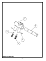
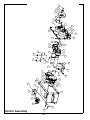
Shifter Disassembly
Refer to Shifter Assembly, page 18.
CAUTION
Alternate between the two access holes evenly to
prevent damage to the housing and bearings during removal. Have an assistant hold the bearings
during removal to prevent dropping them.
20. Remove the oil seal (item #7) from the exciter cover.
1.
Slide the shaft (item #4) out of the shifting yoke (item
#1).
2.
Tip the yoke and catch the detent balls (item #2)
when they fall out.
3.
Drive the spiral pins (item #5) out with a small punch.
4.
Remove the springs (item #3).
5.
Clean and inspect all parts.
21. Remove the breather pin (item #29), felt filter (item
#2), and the retaining ring (item #3) from the cover.
Shifter Assembly
22. Remove all four small retaining rings (item #9) from
the shafts.
Refer to Shifter Assembly, page 18.
1.
24. Clean the shafts and remove both gears and the key
(items #4 #15 and #16).
Insert the shaft (item #4) into the shifting yoke (item
#1). Position the hole in the shaft the same way as
shown in the illustration.
2.
25. Press the bearing (item #18) out of the gear (item
#16).
Insert both detent balls (item #2) into the shifting
yoke.
3.
26. Clean and inspect the bearings, housing, cover,
gears and shafts. Replace parts as needed.
Insert the springs (item #3) into the shifting yoke
behind each detent ball.
4.
Compress the springs and insert the spiral pins (item
#5).
23. Press the bearings (items #6 and #8) off of both ends
of each shaft.
NOTE: Bearings, gears and exciter weights should be
replaced as complete sets.
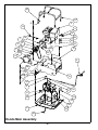
Actuator Assembly
Actuator Disassembly
Refer to Actuator Assembly, page 16.
Refer to Actuator Assembly, page 16.
1.
Install the (2) o-rings (items #4 and #3) onto the
actuator cover (item #5).
2.
Assemble the thrust bearing (item #9), belleville
washer (item #2), and the key (item #1) onto the
actuator shaft (item #8). NOTE: Belleville washer to
be installed with the cupped face up!
1.
Remove the cotter pin (item #11).
2.
Unscrew the castle nut (item #12) halfway.
3.
Tap the top of the castle nut and actuator shaft (item
#8) to release the taper lock.
4.
Remove the castle nut.
3.
Insert the actuator into the cover.
5.
Remove the actuator shaft (item #8) from the
assembly.
4.
Assemble the actuator bushing (item #6) onto the
actuator through the top of the cover.
6.
Remove the key (item #1), belleville washer (item
#2), and the thrust bearing (item #9). from the
actuator.
5.
Assemble the o-ring (item #3) onto the bushing.
6.
Assemble the actuator arm (item #7) and the spiral
pin (item #10) to the bushing. NOTE: Orientation of
the arm is important! Use the figure as an installation
guide.
7.
Remove the washer (item #13) and actuator arm
(item #7).
8.
Remove the o-ring (item #3) and actuator bushing
(item #6).
7.
Apply a bead of silicone sealant to the actuator arm
around the actuator.
9.
Remove the last two o-rings and the spiral pin (item
#10).
8.
Assemble the washer (item #13) and castle nut (item
#12) to the actuator.
9.
Tighten the castle nut and install the cotter pin (item
#11).
10. Clean and inspect all parts.
- 11 -